Vipergear VFS User manual


VFS
Installation Manual
Preface
VFS (Vipergear Force Sensor) is a sensor based on strain gauges, which detect strain when
force is applied to a material.
The VFS is developed for the HOTAS Cougar only and will be connected to the Cougar main
printed circuit board.
The VFS will work with the default HOTAS Cougar software and driver supplied by
Thrustmaster.
The VFS is designed to replace broken gimbals or as an upgrade for your stock HOTAS Cougar.
The VFS will provide you with more accurate/precise handling in your favourite simulator
software.
Please take note that to install the VFS you need to disassemble the stick base completely until
an empty shell has been left.
The only original part that will be re-used is the original stick connector.
* Installation of the VFS is on your own responsibility. Vipergear will not assume any liability
concerning damage caused by installing the VFS.
Thoroughly tested
During the development of the VFS we made sure to go through all the possible ways to
damage the VFS and its connected hardware. We even went so far as shortening out the main
PCB to test the impact of such an event happening.
This left no damage to our Cougar printed circuit board or any attached components.
The PCB supplied with the VFS is Lead-free HASL-RoHS.
All parts on the PCB are high grade electronic parts.
The part where the force is applied to is 3D/printed PLA.
is that strong enough?
Mechanical properties of PLA as used in the VFS
Tensile strength Mpa 59
Tensile strength:
Tensile strength is a measurement of the force required to pull something such as rope, wire,
or a structural beam to the point where it breaks. This is measured at normal room temperature.

For PLA used for the VFS it is 59 Mpa = 59 kgf/sq cm = 839 PSI
So you will have to apply a force exceeding 59 KG per sq/cm or 839 Pounds per sq/inch to
break it.
Basically you never will be able the apply that much of force under normal circumstances.
The 3d printed parts are printed at 100% infill to give it maximum stability and strength.
Rest assured, under normal combat flight circumstances your VFS will not break
due to forces applied!
Package Contents
The Package includes:
1. 1xVFS sensor
2. 1x tombstone
3. 8 x m3x30 2.5mm hex cylindrical bolts
4. 4x m3 brass hex column nuts
5. 4x m3 washers
6. 1x Allen key 3/32
7. 1x Allen key 2.5 mm
8. 4x m3x15
Figure 1 (Package Content)

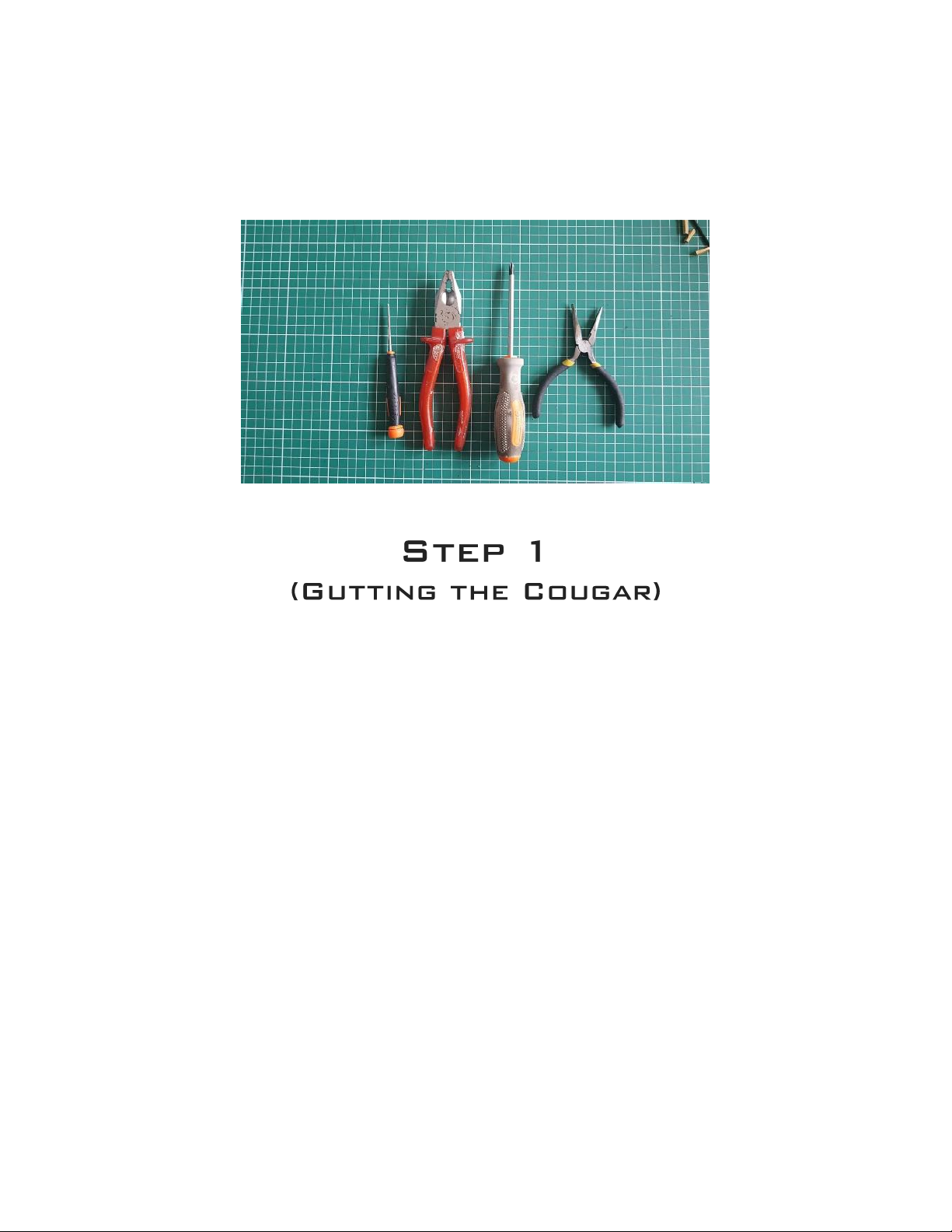
Tools needed (not supplied)
1. Philips screwdriver
2. Pair of pliers or a 5.5 mm spanner wrench
3. Small flathead screwdriver.
Figure 2 (Tools needed)
1. Disconnect the Cougar from the computer,
2. Disconnect the throttle from the stick base and set it aside.
3. Unscrew the stick from its mounting by unscrewing the big fastening nut.
4. On each of the corners on the bottom of the stick base you will locate a screw.
Unscrew them and put the screw away you we need these later again.
Take the bottom cover out of its position and lay it aside.
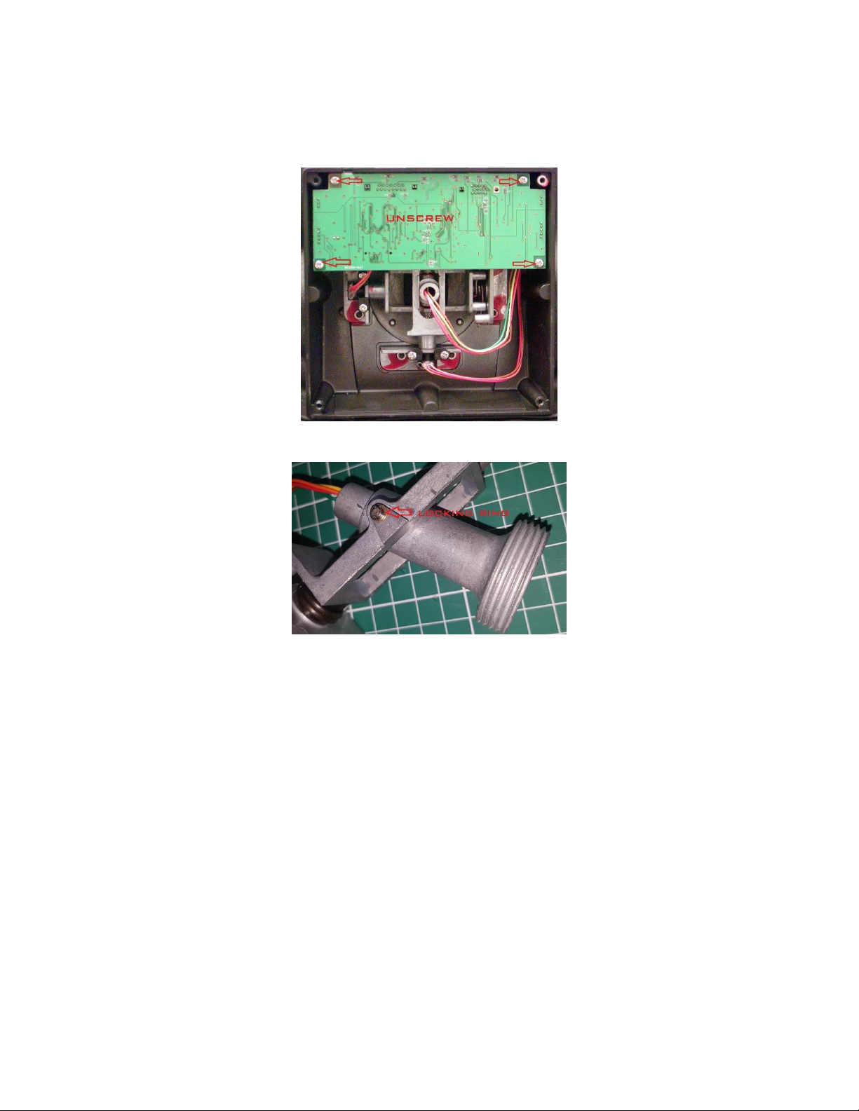
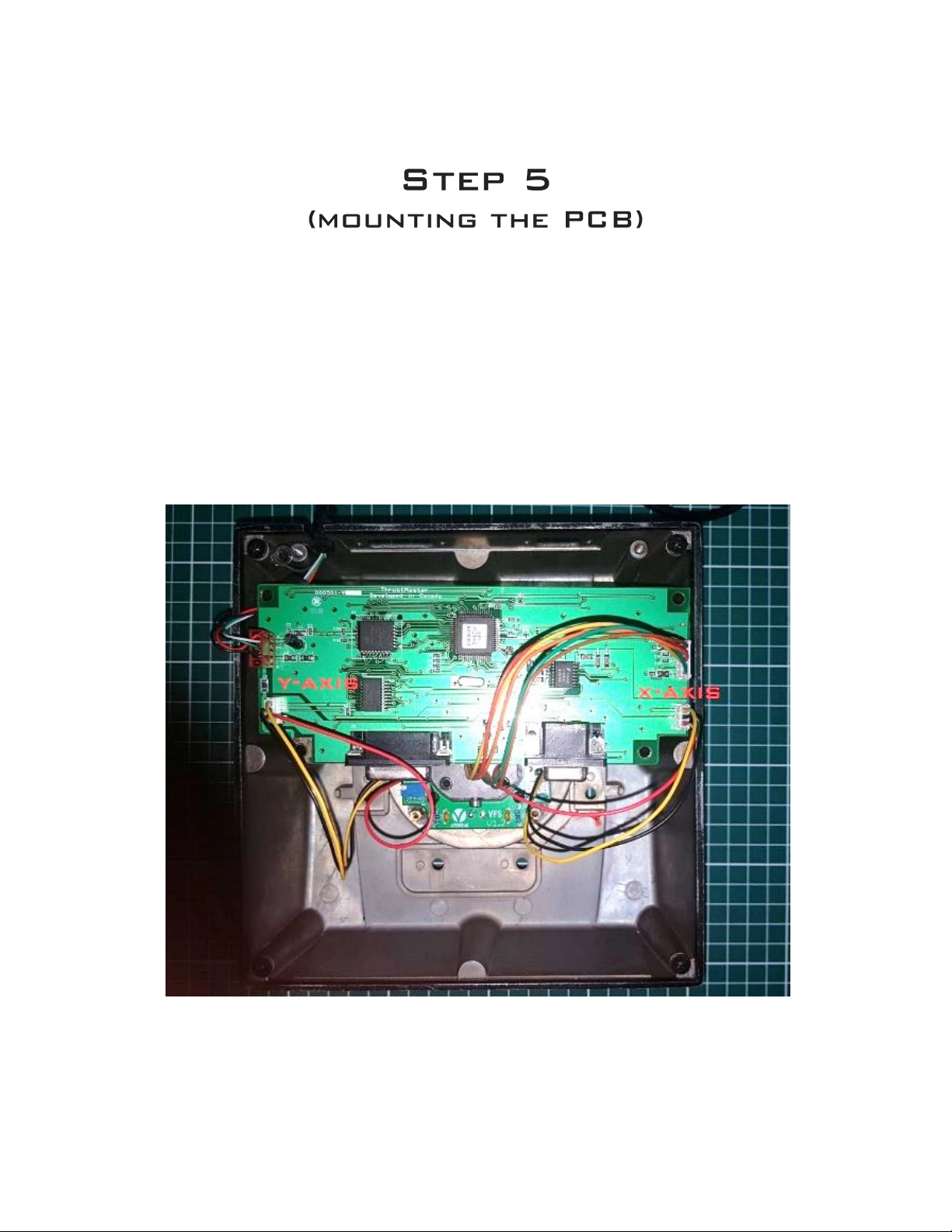
5. The printed circuit board (PCB) is now visible.
Again on each corner of the PCB there is a screw.
Unscrew and set the screws aside (figure 3).
6. Turn over the PCB and disconnect the two pot meter cable and the cable that comes out
of the stick.
You can leave the USB connector connected on the PCB, pull the USB cable out of the
Cougar stick base. Lay the PCB away.
7. The gimbals are screwed in there with eight screws, unscrew these.
Best way is to use the supplied 3/32 allen key and a pair of pliers to grab the nut on the
inside. Once the gimbal is unscrewed you need to wiggle it out of its place.
Best way to get the stick mount out of the base is to pull it out in an angle.
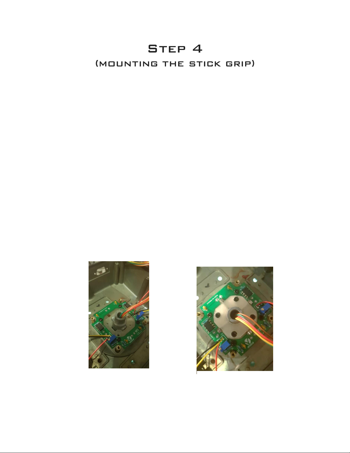
8. All we need from the gimbal is the threaded(stick mount) part in which the stick is placed.
(stick mount)
9. The rest of the gimbal can be stored somewhere safe.
To get the stick mount out of the gimbal gently pry of locking ring(figure,4) with a little

screw driver, pull out the pin and there is you’re stick mount. Put the locking ring back on
the pin so you won’t lose it. Gutting done.(figure,5)
Figure 3 (Original Cougar PCB dismount)
Figure 4 (remove the locking)

Figure 5 (parts needed for VFS installation stick mount and the eight gimbal screws)
1. Bolted on top of the empty shell there is a steel ring that keeps the rubber dustcover in
place.
Replace the four crosshead screws with the m3x30 allen key bolt, drive them tightly and
all the way in.
2. Now it is a good time to bolt back the eight screws which are used to mount the gimbals
in place, the only use for them is to prevent dust entering your stick base.
3. On the 3D printed part there is an indicator in a chevron shape(figure,6). Turn the shell
upside down place the sensor PCB towards you and with the chevron facing the d-sub
connectors holes over the bolts. Slide one washer over each bolt. Get the brass column
nuts and bolt the sensor down by hand.
4. Now you that you have placed the column bolt you have to tight them down using a pair
of pliers, best way is to tighten opposite corners at the time.
So from left top, to right bottom, to right top to, left bottom.
Turn them as tightly as possible.

Figure 6 (chevron indicator)
1. Prepare the tombstone by driving in the 4 m3x20 bolts on each side of the tombstone,
don’t drive them in completely.
2. The end of the bolt should be equal or a bit less to the inner wall of the thumb stone.
3. Place the 4 m3x30 bolts in each hole on the top of the tombstone.
4. Push the m3x30 down by hand

Figure 7 (tombstone)

Figure 8
Figure 9
1. Take the stick grip, place it on the stick mount and tighten it up.
Feed the wire of the stick grip through the top of the Cougar base and through the
sensor.
Before you push the stick trough the sensor face the trigger to left or right side wall.
2. Push it down as far as possible, it is a tight fit and will need some light force to push
through the sensor.
Turn the stick grip facing the trigger front side of the stick(trigger should face the d-sub
connector slots of the shell).
3. Push it down as far as possible, it is a tight fit and will need some light force to push
trough.(figure 8)
Turn the stick grip facing the trigger front side of the stick
(trigger should face the d-sub connector slots of the shell).
Push the stick grip down as far as possible.
4. Get the tombstone and face the two guide pins to the PCB.
Feed the stick grip wire through the tombstone.
Align the guide pins with the slots in the sensor.
Push the tombstone all the way down over threaded part(again it may need some force).
5. Drive the top screws down the sensors and tighten them down using the 2.5mm allen key
as tight as possible. Tighten the four screws in the sidewalls of the tombstone, hand tight
is just enough.
positioned in the tombstone mounted
sensor correctly

1. Get the PCB, connect the stick grip connector back in place.
2. Connect the sensor cables as shown on figure 10 right side x-axis left side y-axis.
3. Place the PCB back in its originated position, don’t forget to place the grounding wire
back.
4. Blot the PCB down using the original screws.
5. Congrats you just installed the VFS.
Figure 10 (VFS Axis Connections)

We recommend using the auto calibration on start-up .
1. Connect the cougar to your PC and open up the HOTAS CCP.
2. Go to the start-up& calibration tab.
3. Click the manual calibration.
4. Now go to the point where it states move y-axis forward, adjust the y-axis trim pot using a
small flathead screwdriver until you get a raw value of ~320 anything between 320 and
330 will be fine.
5. Click next until you get to the point move x-axis to the left most, turn the x-axis trim pot till
you get a raw value of ~320 anything between 320 and 330 will be fine.
6. Don’t finish the calibration steps, you can exit the manual calibration now.
7. Don’t forget the to screw the bottom cover back in place.
If you want to go in depth about calibration I recommend reading the calibration
document in your Cougar install folder.
Figure 11

The sensor is equipped with a instrumental amplifier and some resistors.
The value of the resistor can drift by temperature changes.
These little resistance drift will be amplified by the amplifier which lead to drastic changes in the
output.
Every time you fire up your computer and the cougar comes alive the Cougar will calibrate
automatically and compensates the temperature drift .
Note:
If you have connected the Cougar to a powered USB hub the automatic calibration won’t work
cause the Cougar stays powered.
We recommend to connect the Cougar directly to the computer cause these USB ports are not
powered while the computer is turned off.
The conclusions are based on our personal experiences while developing the VFS.
You might find some mechanical play in the stick while using the VFS. Tighten up the screw on
the bottom part of the stick might resolve the play, but eventually the play will return.
A horse shoe ring (figure 12 )is included to counter the mechanical play for good.
Just press it between the stick and the fixture ring.(figure 13)
Figure 12
Figure 13

PCB Lead-free HASL-RoHS
Operating voltage 5v
3D printed material PLA
Range at 2.5 KG applied force Full range
Manual version 1.1 - March 2019
Vipergear
www.vipergear.eu
Table of contents