Anschlussanleitung
Anschluss Stella Light-D-E- 090914.doc
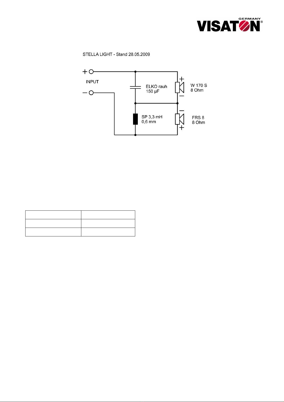
STELLA LIGHT
Zum Anschluss der Kabel und Montage der
Frequenzweichenbauteile werden folgende
Werkzeuge benötigt:
•Lötkolben mit 30–50 Watt
•Elektroniker-Lötzinn
•Seitenschneider
•Heißkleber oder vergleichbarer Kleber
•Maßband
Zunächst werden die Kabel auf die korrekte Länge
entsprechend der Tabelle zugeschnitten.
Frequenzweiche
FRS 8 (Breitbänder) 150 cm
W 170 S (Tieftöner) 150 cm
Anschließend werden die Kabelenden auf 10 mm
Länge abisoliert, einzeln fest verdrillt und verzinnt. Um
Verdrahtungsfehler zu vermeiden, ist es sinnvoll, die
Kabel mit einer Markierung zu versehen (z.B.
beschriften mit „FRS 8 +“ usw.).
Da die Frequenzweiche aus nur zwei Bauteilen
besteht und der Bausatz „Stella Light“ so preiswert
wie möglich sein sollte, wurde bewusst auf eine
Platine verzichtet. Um einen optimalen und möglichst
einfachen Service gewährleisten zu können, empfiehlt
es sich, die Frequenzweichenbauteile direkt auf das
Anschlussterminal „ST 77“ mittels Heißkleber zu
kleben. Dabei kann die Spule „SP 3,3 mH“ direkt auf
die Rückseite des Terminals geklebt werden und mit
dem Minus-Pol des Terminals verlötet werden. Um ein
Lösen der Bauteile vom Terminal zu vermeiden, sollte
der Produktaufkleber des Terminals vorher entfernt
werden. Nun kann der Kondensator „ELKO 150 µF“
direkt auf die Spule geklebt und an einem Ende mit
dem Plus-Pol des Terminals verlötet werden. Wichtig
bei der Verklebung beider Bauteile ist die Platzierung
der Bauteile auf der Terminalrückseite. Die Bauteile
dürfen dabei nicht über den Rand des Terminals
schauen, da sonst eine einwandfreie Positionierung
des Terminals am Gehäuse nicht mehr möglich ist.
Nun müssen noch die offenen Enden der Spule und
des Kondensators verlötet werden. Dank des
längeren Pins des Kondensators ist dies ohne
zusätzlichen Kabelaufwand möglich.
Die Kabel werden nun entsprechend dem Frequenz-
weichenschaubild oben angelötet. Der Plus-Pol des
„FRS 8“ kann dabei direkt an den Minus-Pol des
Terminals, der Plus-Pol des „W 170 S“ direkt an den
Plus-Pol des Terminals angelötet werden. Die nun
noch offenen Kabelenden der beiden Lautsprecher
werden mittels Lötzinn an die Verbindung zwischen
Spule und Kondensator gelötet. Achten Sie bitte
hierbei besonders darauf, dass kein Kurzschluss zu
einem benachbarten Kabel entsteht. Außerdem ist es
wichtig, die markierten und die unmarkierten Adern
der Kabel wie im Anschlussplan angegeben
anzulöten. Überprüfen Sie zum Schluss bitte noch
einmal den fertigen Aufbau der Weiche mit Hilfe des
Anschlussplanes. Für einen zusätzlichen Schutz
können offene Adern und Drähte mittels Heißkleber
fixiert und gesichert werden.
Danach werden die Kabel im Lautsprechergehäuse
verlegt, so dass ausreichend Kabel für eine bequeme
Bearbeitung aus den Gehäuseöffnungen schauen.
Beim Anschluss der Kabel an die Lautsprecher muss
unbedingt auf korrekte Polarität geachtet werden.
Stand 14.09.09