Maintenance schedule Visatron VN2020
By conducting regular maintenance, the product will have a long service life. If the maintenance intervals are not
observed, the oil mist detector may fail prematurely. It is essential that you follow the given sequence for the work.
NOTE: All maintenance steps should be performed while engine is stopped!
•M1 | Clean infrared sensors in measuring head
and replace seal on inspection cover.
•M2 | Exchange seal on connection box and
check bellows and suspension system between
measuring head and base plate for damage.
•M3 | Exchange filter in pressure regulator and
check negative pressure in measuring head.
•M4 | Clean suction/pipe system with
compressed air.
•M5 | Functional test with smoke test to be
carried out.
Every 6
months or
4 000
operating
hours.
(whatever
comes first)
Maintenance kit
for VN2020 -
small kit –Part
no.: 155003
Cleaning kit –
Part no.: 151482
Smoke test kit –
Part no.: 151780
Main two-year service (2 years) by authorized and
certified Schaller personnel only!
•Service and test of complete Oil Mist Detector
installation incl. software check and upgrade if
necessary.
•Replacement of mayor part kit for VN2020.
•Service certificate to be approved by authorized
personnel!
Please contact us for authorized personnel at:
Every 24
months or
16 000
operating
hours.
(whatever
comes first)
Maintenance kit
for VN2020 –
Part no.: 155004
Cleaning kit –
Part no.: 151482
Smoke test kit –
Part no.: 151780
Main two-year service (2 years) by authorized and
certified Schaller personnel only!
•Perform procedure 1 & procedure 2.
•Replace measuring head or complete oil mist
detector.
Please contact us for authorized personnel at:
Every 48
months or
32 000
operating
hours.
(whatever
comes first)
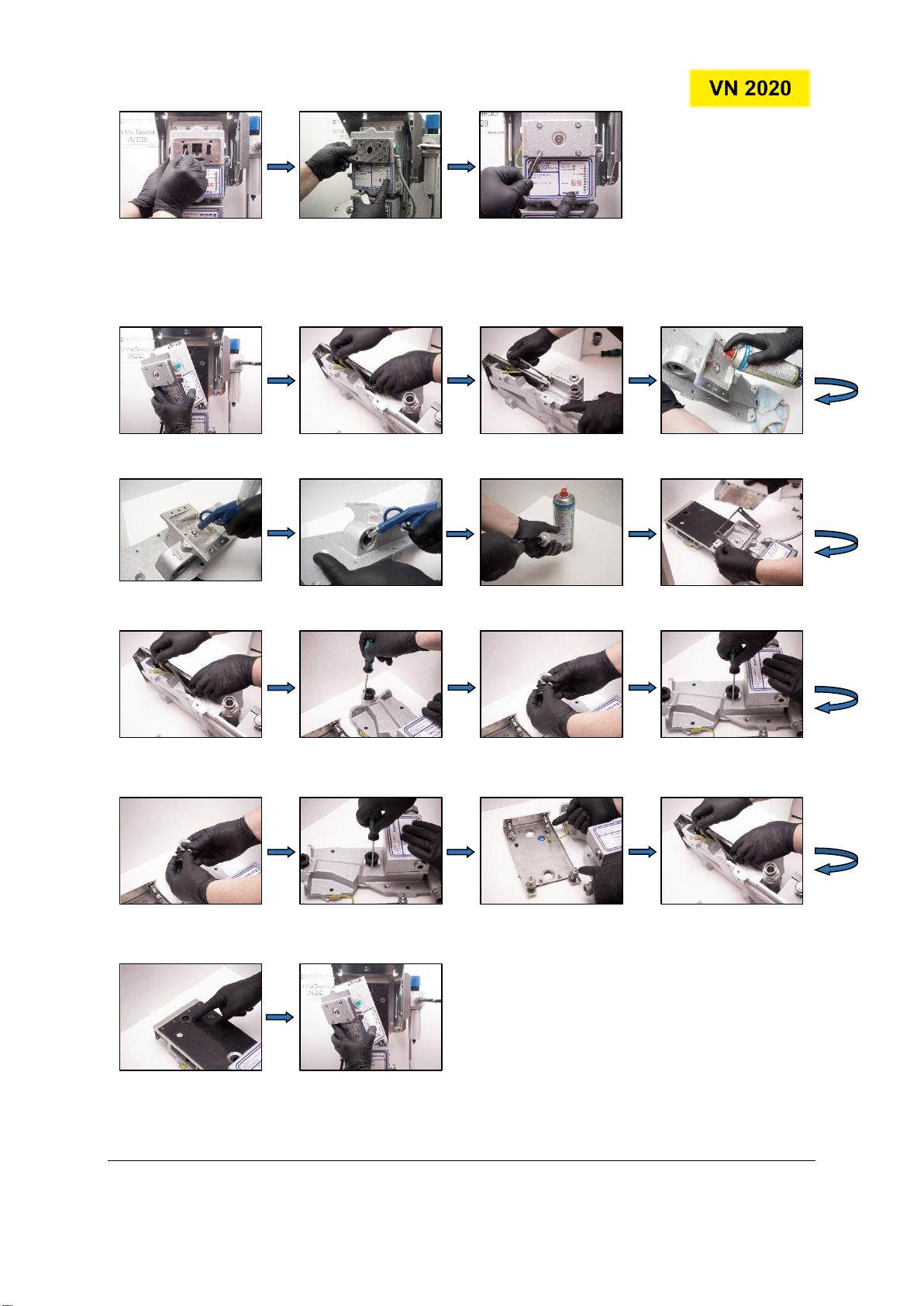
Procedure 1:
M1 | Clean infrared sensors in measuring head and replace seal on inspection cover.
1. Loosen the captive
screws on the inspection
cover.
2. Open the inspection
cover.
3. Use the cleaning fluid
and cotton sticks.
4. Clean the glass on the
transmitter diode on the
right side until it is clean.