eco-SPRAY
Commissioning and maintenance instructions
6 / 19 Version 1.0 Copyright ©
2.1 Spray head combinations
We recommend selecting the air cap (B)
with the corresponding precision dosing
needle (A) depending on the medium
viscosity.
The appropriate combination must be
selected and tested separately for each
application (viscosity, dosing quantity/
time and temperature).
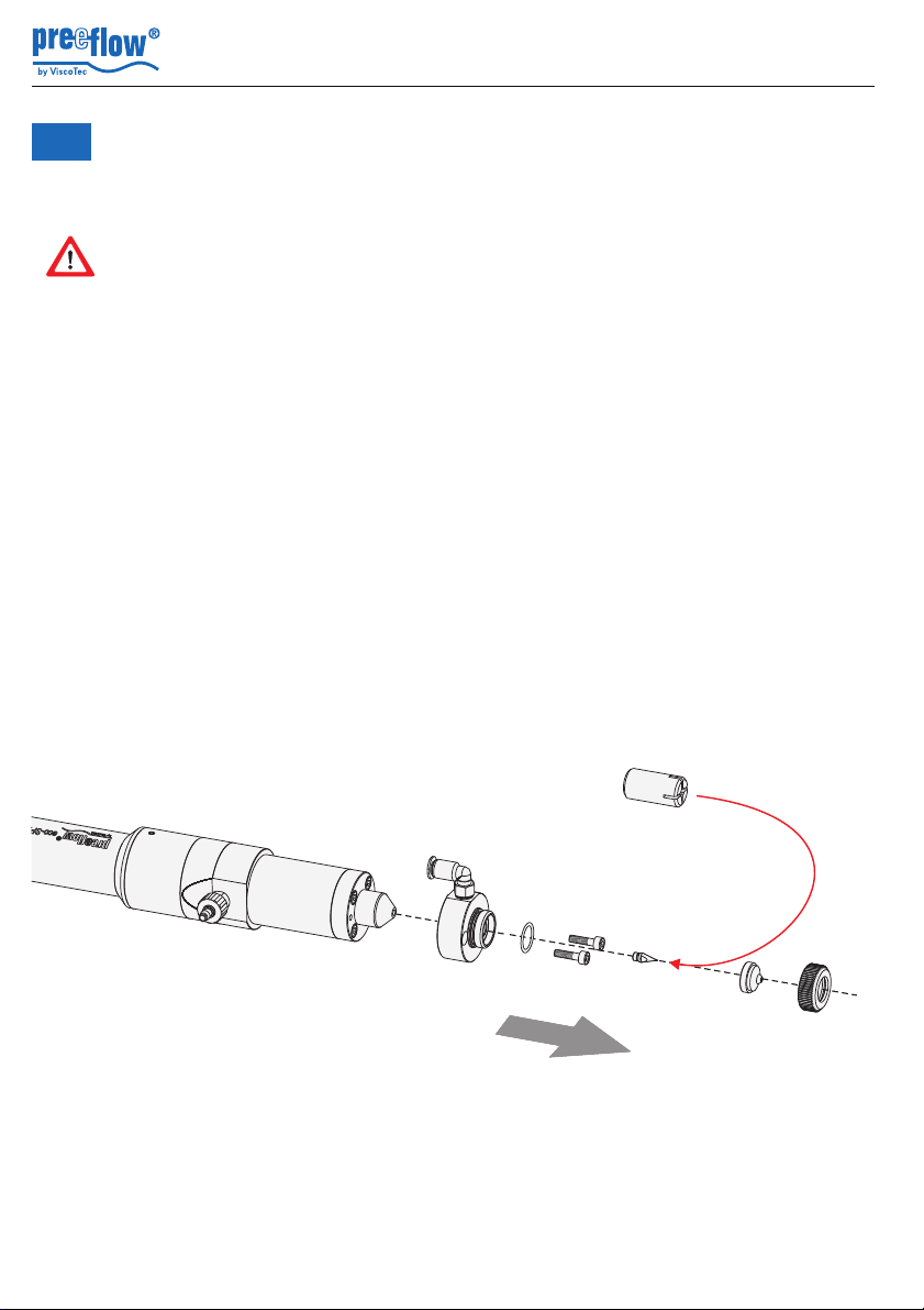
2.2 Retrofitting the spray head
• Undo the union ring (2)
• Remove the air cap (29). The seal (30) remains either in the spray head or stuck to the
air cap (29)
• Carefully attach the nozzle mounting tool (31) to the precision dosing needle (28),
unscrew the precision dosing needle and replace it with another one
• Attach an air cap (29) and re-tighten the union ring (2)