VISIO VP-600 User manual

VP-600
19A
EC - Declaration of Conformity
We declare that our products (lighting equipments) comply with the following
specification and bears CE mark in accordance with the provision of the
Electromagnetic Compatibility (EMC) Directive 89/336/EEC.
EN55014-2: 1997 A1: 2001, EN61000-4-2: 1995; EN61000-4-3: 2002;
EN61000-4-4: 1995; EN61000-4-5: 1995, EN61000-4-6: 1996,
EN61000-4-11: 1994.
&
Harmonized Standard
EN60598-1: 2000+ALL: 2000+A12: 2002
Safety of household and similar electrical appliances
Part 1: General requirements
V Power
VP-600
User Manual
Please read the instructions carefully before use

VP-600
1A
TABLE OF CONTENTS
1. Safety Instruction
2. Features
3. Technical Specification
4. Installing Instructions
5. Main Function
6. Overview
6.1 Front View
6.2 Rear View
7. DMX Controller
8. DMX512 Configuration
9. DMX512 Connection
9.1 XLR Connection
9.2 RJ45 Connection
VP-600
18A
9.2 RJ45 Connection
DMX Input, Output LED module Input
RJ45 Connector RJ45 Connector
Front view of the Connector Front view of the Connector
Pin 1: Not connected Pin 5: Not connected Pin 1: Red LED + Pin 5: Red LED -
Pin 2: Not connected Pin 6: Data + Pin 2: Green LED + Pin 6: Green LED -
Pin 3: Not connected Pin 7: Data - Pin 3: Blue LED + Pin 7: Blue LED -
Pin 4: Not connected Pin 8: GND Pin 4: White LED + Pin 8: White LED -

VP-600
17A
adapter-cable.
2. At last unit, the DMX cable has to be terminated with a terminator. Solder a 120
ohm 1/4W resistor between pin 2(DMX-) and pin 3(DMX+) into a 3-pin XLR-plug
and plug it in the DMX-output of the last unit.
3. Connect the unit together in a `daisy chain` by XLR plug from the output of the
unit to the input of the next unit. The cable can not branched or split to a `Y`
cable. DMX 512 is a very high-speed signal. Inadequate or damaged cables,
soldered joints or corroded connectors can easily distort the signal and shut
down the system.
4. The DMX output and input connectors are pass-through to maintain the DMX
circuit, when one of the units’ power is disconnected.
5. Each unit needs to have an address set to receive the data sent by the controller.
The address number is between 0-511 (usually 0 & 1 are equal to 1).
6. The end of the DMX 512 system should be terminated to reduce signal errors.
7. 3 pin XLR connectors are more popular than 5 pin XLR.
3 pin XLR: Pin 1: GND, Pin 2: Negative signal (-), Pin 3: Positive signal (+)
5 pin XLR: Pin 1: GND, Pin 2: Negative signal (-), Pin 3: Positive signal (+),
Pin 4/Pin 5: not used.
VP-600
2A
1. Safety Introductions
Please read the User Manual carefully as it includes important information regarding
details of operation, maintenance and technical data. Keep this manual with unit for
future consultation.
WARNING!
yAvoiding any flammable liquids, water or metal objects enter into the unit.
yIf any liquid spill on the unit, disconnect the power supply immediately.
yWhen serious operation problem happen, stop using the unit immediately and
contact your local dealer for service.
yDo not open the unit because there are no user serviceable parts inside.
yNever try to repair the unit yourself. Repairs by unqualified people may cause
damage or faulty operation. Please contact your nearest dealer for any service.
CAUTION!
yAfter removed the package, make sure the unit is not damaged in any way. Don’t
use it with doubt and contact an authorized dealer.
yNever use the unit under the excessive humidity and a temperature over 40℃.
yDo not try to dismantle or modify the unit.

VP-600
3A
2. Features
y7 Channel modes (Mode 1 & Mode 2 for RGBW; Mode 3 &Mode 4 for RGB;
Mode 5 &Mode 6 for CW and WW colors; Mode 7 for single color) enables V
Power to control passive lighting fixtures that fitted with different LED emitters.
yComes with 3 chase groups, each group has 8 chases (3 editable chases); and
each chase can have up to 42 scenes. For editing the chases, Visio has
developed a software (option) that enables you to edit the chases easily.
yIt comes with the built-in clock for editing your shows. You can edit max. 30
shows (choose from the chases) in one week, and different time period per day.
yUser can run the chase manually step by step by pressing the manual button.
yExcellent fade effect, and auto running function.
yLCD display for easy navigation.
3. Technical Specifications
yDMX Input
Control: DMX 512
DMX connection: RJ45 or 3 pin XLR
yOutput
Max.Power Output: 600W
Output Voltage: DC 48V
Max.Output Current: 350mA per color
Max.Load per zone: RGB & RGBW mode-Each color 12 LEDs max.
White mode-Each white 24 LEDs max.
yInput Voltage: 100V-240V~50/60Hz
yFuse: T6.3A
yDimension:440×416×96 mm
yWeight:7.8kgs
VP-600
16A
10 Channels:
4 Channels for RGBW:
9. DMX512 Connection
9.1 XLR Connection
1. If you using a controller with 5 pins DMX output, you need to use a 5 to 3 pin

VP-600
15A
4 Channels:
20 Channels:
11 Channels:
VP-600
4A
4. Installing instructions
The VP-600 should be placed on a non-flammable flat surface in any
orientation and fixed by screws. There are six mounting holes on the
housing. Ensure that installation place is enough ventilated.
V Power could control the LED fixtures such as V Aqua, V Bar, V Ceiling, V Inground,
V Net, V Wall and CW36, the VP-600 power output is 600 watt (10×60W).

VP-600
5A
5. Main Function
To select any function, press MENU button until the required one is shown
on the display. Select the function by ENTER button and the display will blink.
Use DOWN and UP button to change the mode. Once the required mode
has been selected, press ENTER button to setup. Back to the functions
without any change press MENU button.
Press MENU button for 3 seconds to exit the functions, press “Chase Group
1”, “Chase Group 2” or “Chase Group 3” button to run the chase built-in or
you have programmed. Enter chase group, the LED on, then press the
chase group button again to choose the chase. Once the chase has been
selected, press “Manual” button into manual mode, the LED on, you can
choose the chase step by step; press “Fade” button into fade mode, the LED
on, the unit will run all steps of the chase automatically, at this time, you can
press UP/DOWN button to adjust the fade time; press the “Auto” button into
auto mode, the LED on, the unit will also run all steps automatically, and you
can press UP/DOWN button to adjust the wait time; press the “Blackout”
button, the LED on and the unit into blackout mode.
VP-600
14A
40 Channels:
30 Channels:

VP-600
13A
8. DMX512 Configuration
43 Channels:
VP-600
6A
The main functions are shown below:

VP-600
7A
Address
Press the MENU button up to when the Address is shown on the display.
Pressing ENTER button and 1will blink. Use DOWN and UP button to
change the DMX 512 address (1-512). Once the address has been selected,
press ENTER button to setup or automatically return to the main functions
without any change after 8 seconds. Back to the previous functions without
any change press MENU button.
Channel Mode
Press the MENU button up to when the Channel Mode is shown on the
display. Pressing ENTER button and 1will blink. Use DOWN and UP button
to select 1(43 channels) or 2(40 Channels) …… or 7(10 Channels)
channel mode. Once the mode has been selected, press ENTER button to
setup. Back to the main functions without any change please press the
MENU button.
Adjust Time
Press the MENU button up to when the Adjust Time is showing on the
display. Press ENTER button and Friday will blink. Use DOWN and UP
button to select Monday or Tues …… or Sunday. Press the ENTER button
to setup hour and 14 will blink, use DOWN and UP button to select hour,
press the ENTER button to setup minute and 58 will blink, use DOWN and
UP button to select minute, press MENU to store and back to the main
functions.
Edit Show
Press the MENU button up to when the Edit Show is showing on the display.
Press ENTER button and 01 will blink. Use DOWN/UP button to select show
(1-30), press ENTER button to setup and use DOWN/UP to edit Time (for
example: set the unit on F (from) Monday15:15 T (to) Monday 15:20) and
Chase (choose Group 1-3, Num 1-8 and edit F-fade time and W-wait time),
Press MENU button to store and back to the main functions.
VP-600
12A
stops blinking or storing automatically 8 seconds later. To go back to the
main functions without any change press the MENU button again. Please
refer to the following diagram to address your DMX512 channel for the first 4
units.
43 Channels:
40 Channels:
30 Channels:
4 Channels:
20 Channels:
11 Channels:
10 Channels:
4 Channels:

VP-600
11A
6.2 Rear View
1. DMX IN DMX Input RJ45 or 3 pin XLR socket
2. DMX OUT DMX Output RJ45 or 3 pin XLR socket
3. FUSE T6.3A For protecting the unit when the transient current is too big.
4. POWER Power cable for AC input.
5. LED DC power & signal output for linking LED fixtures.
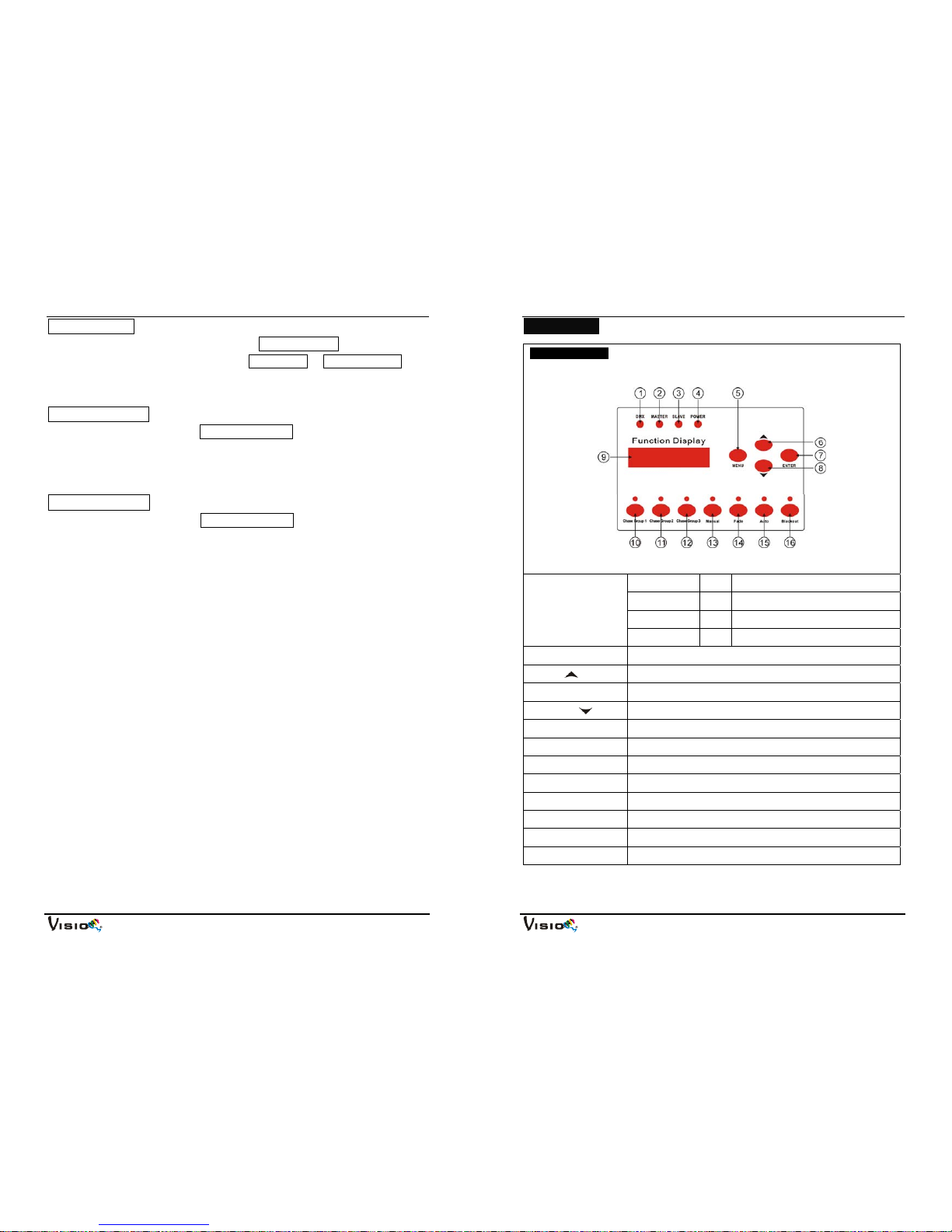
7. DMX Controller
Using universal DMX controller to control the units, you have to set DMX
address from 1 to 512 channel so that the units can receive DMX signal.
Press the MENU button up to when the Address is showing on the display.
Pressing ENTER button and the display will blink. Use DOWN and UP
button to change the DMX512 address. Once the address has been
selected, press and keep ENTER button pressed up to when the display
VP-600
8A
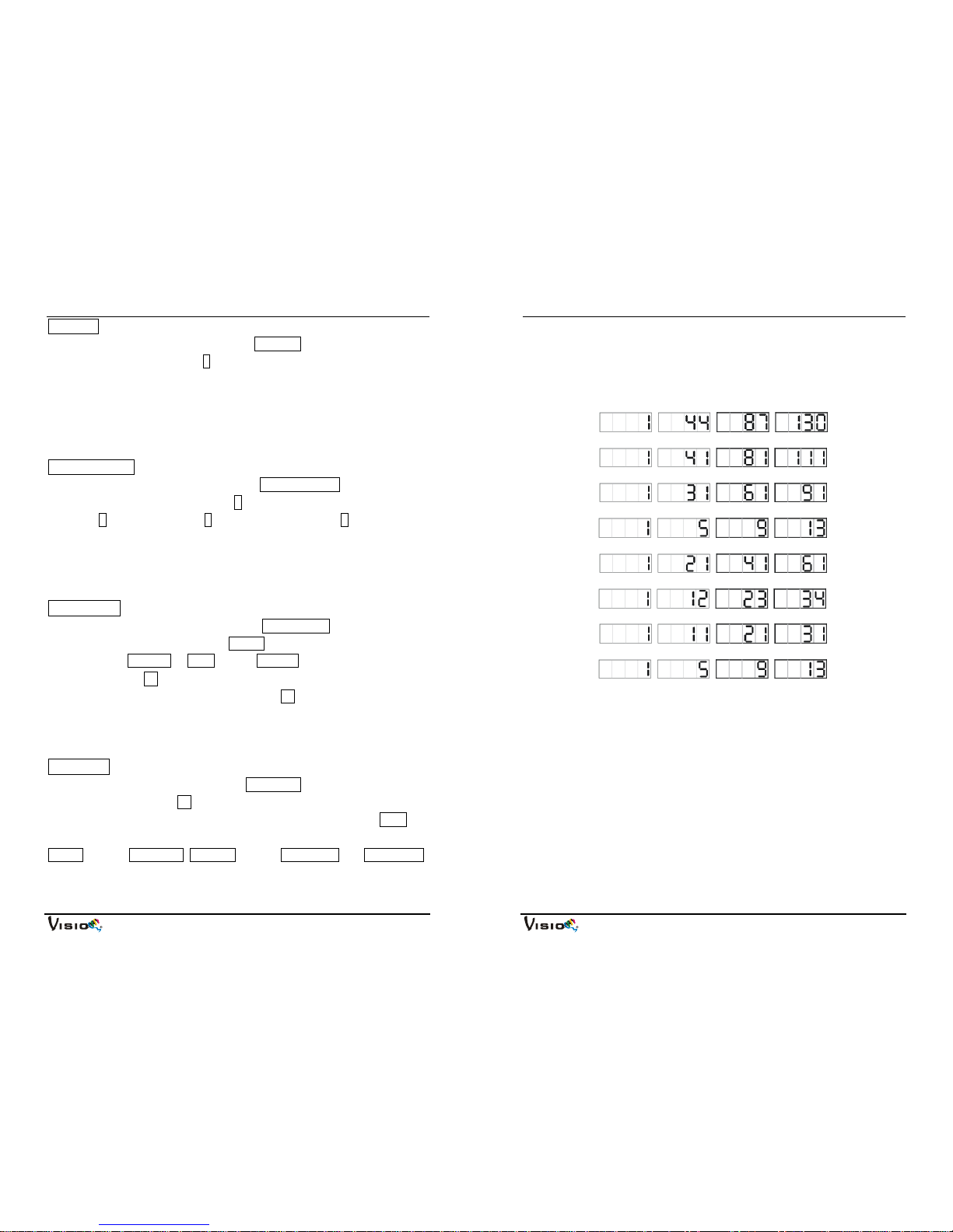
Edit Chase (only chase number 6~8 are editable)
Press the MENU button up to when the Edit Chase is showing on the
display. Press ENTER button and 1will blink, use UP/DOWN button to
choose group 1, 2 or 3, press ENTER button to setup and use UP/DOWN to
set Num-number (06-08), Leng-length (01-42, the steps, you choose from
the total amount of steps, you want to run, for example, if the total amount of
steps you set is 42, you can choose only first 1-10 steps to run) and Value
(to set step, P-A (output all) or 1-10, C-Color, W-White, D-Dimmer), press
ENTER button to setup. Back to the main functions without any change
please press the MENU button.
Manual Test
Press the MENU button up to when the Manual Test is showing on the
display. Press ENTER button and 1will blink, use UP/DOWN button to
choose P-A (output all) or 1-10, press ENTER button to store, use
DOWN/UP to set D-Dimmer, S-Strobe, R-Red, G-Green, B-Blue, W-White,
press ENTER button to setup. Back to the main functions without any
change please press the MENU button.
White Balance
Press the MENU button up to when the White Balance is showing on the
display. Press ENTER button and 1will blink, use UP/DOWN button to
choose P-A (output all) or 1-10, press ENTER button to store, use
DOWN/UP to set R-Red, G-Green, B-Blue, press ENTER button to setup.
Back to the main functions without any change please press the MENU
button.
Auto Test
Press the MENU button up to when the Auto Test is showing on the display.
Press ENTER button Testing will blink on the display and the unit will run
self-test by built-in program. To go back to the main functions please press the
MENU button.

VP-600
9A
LCD Backlight
Press the MENU button up to when the LCD Backlight is showing on the
display. Press ENTER button to choose Always On or Auto Blackout. To go
back to the functions please press the MENU button.
Fixture Use Time
Press the MENU button up to Fixture Use Time, it will show the number of
working hours of the unit. To go back to the main functions please press the
MENU button.
Software Version
Press the MENU button up to Software Version, It will show the version of
software of the unit. To go back to the main functions please press the
MENU button.
VP-600
10A
6. Overview
6.1 Front View
1. DMX On DMX Input
2. MASTER On Master Mode
3. SLAVE On Slave Mode
LED
4. POWER On Power on
5. Menu Press the button to select the programming functions.
6. Up Press the button to go forward for the desired functions.
7. Enter Press the button to confirm the selected functions.
8. Down Press the button to go backward for the desired functions.
9. Display To show the various menu and selected function
10.Chase Group 1 Press the button to run chase group 1, the LED will be on.
11.Chase Group 2 Press the button to run chase group 2, the LED will be on.
12.Chase Group 3 Press the button to run chase group 3, the LED will be on.
13.Manual Press the button into manual mode, the LED will be on.
14.Fade Press the button into fade mode, the LED will be on.
15.Auto Press the button into auto mode, the LED will be on.
16.Blackout Press the button to blackout the unit, the LED will be on.
Table of contents
Other VISIO Dj Equipment manuals
Popular Dj Equipment manuals by other brands

Creative Lighting Solutions
Creative Lighting Solutions REVO Compact Basic manual

ADJ
ADJ VIZI CMY300 User instructions

Elumen8
Elumen8 MP 15 LED Fresnel DTW user manual

Elumen8
Elumen8 Virtuoso 2000 Fresnel RGBAL user manual

Wibre
Wibre 5.0690.09.01 installation manual

TECshow
TECshow DUALTEC 3-IN-1 user manual