Vision Works VWIC904-HDWL User manual

ITEM
Warranty Information
Return Policy
Safety Information
What's Included
Camera Specs
Monitor Specs
Camera Assembly
Monitor Assembly
Installation Instructions
Monitor & Remote Operations
PAGE
1
1
1
2
2
3
3
4
4-5
5-6
DURABLE
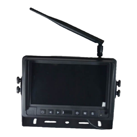
9" MONITOR HD WIRELESS
CAMERA SYSTEM
Updated
3 / 4 / 2 0 2 1
VWIC904-HDWL Owners Manual
VISIONWORKSCAMERAS.COM TECHNICAL SUPPORT: 1-541-995-8000
QUALITY AFFORDABLE
LEAVE SCREEN PROTECTOR ON MONITOR TO HELP
REDUCE GLARE IF USING POLORIZED GLASSES

No merchandise should be returned to Visionworks for credit unless accompanied by a return
authorization number from our company. You will receive credit for the full amount of the
return if the merchandise is returned within 30 days of the invoice date. Any merchandise
that is not returned within 30 days of the invoice date is subject to a restocking fee of 15%.
Contact your Visionworks dealer for return information.
Merchandise that has been special ordered cannot be returned for credit. Non-stock items
returned for credit will be subject to vendor’s return policy.
PAGE 01 OWNERS MANUAL - WARRANTY INFORMATION, RETURN POLICY, SAFETY
INFORMATION
WARRANTY
INFORMATION
Thank you for purchasing a Visionworks camera system. We
have taken great care to provide you with a top-quality
product. Visionworks comes with a one-year warranty (from
the date of purchase) that covers defective materials or
workmanship, as long as no wiring or parts are modified in
any manner. If our product is found to be modified the
warranty will be nullified. The camera has a three-year
warranty if you register on our website. Please go to
visionworkscameras.com and click on "Warranty
Registration" or use the QR Code to increase your warranty
from one year to three years.
RETURN POLICY
SAFETY &
IMPORTANT
INFORMATION
To avoid electrical shock and maintain optimal functionality, do not
open the enclosures. High voltage may be present and there are no
user serviceable parts inside. All warranties will be void should any
enclosures be tampered with in any way.
To prevent short circuit, make sure that the system is not plugged in or
receiving power while making system connections. In the event of a
system short circuit, replacement of the 3A fuse will be required. Fuses
are located under the threaded tip of the cigarette lighter, and inside
the threaded barrel section of the RED 12 volt supply wire.
Replacement fuses are not included with this kit.
To ensure that you do not drain your battery, please disconnect the
cigarette adaptor when not in use.
The camera is completely weatherproof, but the monitor is NOT and
should NOT be exposed to water. Please ask about weatherproof
monitors if you do not have a weatherproof cab.

PAGE 02
OWNERS MANUAL - WHAT'S INCLUDED & CAMERA SPECS
WHAT'S
INCLUDED
CAMERA
SPECS
Low Temp. Rating
Identify your parts and find our what is included in your
Visionworks camera system.
HD Wireless
Camera & Antenna Camera Mounting
Hardware
Monitor Assembly
Hardware Monitor Visor &
Mounting Bracket Cigarette Lighter Adapter,
2 ACDC Adapter
Camera Hardwire, Cable,
Audio Jack, Scotch clips
Fig 1.
9" HD Monitor
Remote
Model
Sony
Weatherproof Rating
Viewing AngleResolution Lens
Connection Type
1080P HD
Resolution 90 Degree 3.6 mm
-20 C -4 FIP68 4 Pin
Fig 3. Fig 4.
Fig 5. Fig 6.
Fig 9.
Fig 8.
Fig 10.
Suction Cup
Monitor Mount
Fig 7.
Camera Magnet
Fig 2.

PAGE 03 OWNERS MANUAL - MONITOR SPECS & CAMERA ASSEMBLY
MONITOR
SPECS
Built-in
Recording
Yes (up to 128
GB SD Card)
Model
904
Aspect Ratio
Screen Size
Luminance
9 inches
16:9
500 cd/md2
Resolution
1024 x 600
Audio & Video
4 video/4
audio input
(dual channel
single image
display
Language
Mount Type
Multi-Language
U-Type
Sunshade
Removable
Voltage
12V-36V
System
PAL & NTSC
automatically
OSD Menu
Display Menu,
Brightness,
Color, Contrast
Adjustable
Set Up
Mirror for
individual image,
can set reserve
trigger delay in
settings
CAMERA
ASSEMBLY
Fig 1. Fig 2. Fig 3.
1 - Scew in the antenna provided into the back of the camera.
2 - Remove flat washer and nut on magnet assembly. Position and align
center hole of camera and bracket assembly on top of magnet.
3 - Install bolt from underside of magnet and secure with flat washer and
nut. Tighten this connection.
4 - Secure camera and set viewing angle with the four allen wrench bolts
(inside camera mounting hardware). You can always adjust your camera
viewing angle later.
Tip: Although the magnet contains 65lb pull force, we recommend mounting
your camera on a flat surface to minimize vibration. Sometimes a zip tie can
be used in addition to fasten the camera as a preventative measure in the
event the camera is knocked off.
TEMPORARY MOUNTING
For permanent mounting, it is recommended that you remove the magnet and
attach the camera bracket to any flat surface with the two truss head screws
provided in the kit (inside camera mounting hardware).
Secure camera and set viewing angle with the four allen wrench bolts (inside
camera mounting hardware). You can always adjust your camera viewing
angle later.
PERMANENT MOUNTING
Antenna
Magnet
Bolt Nut
Magnet Bolt
Magnet
Washer
Allen
Wrench Bolt
Allen
Wrench Bolt
Allen
Wrench
Bolt
Allen
Wrench
Bolt
Truss head
Screws
Allen
Wrench
Bolt
Allen
Wrench Bolt
Allen
Wrench
Bolt
Antenna

MONITOR
ASSEMBLY
Beforeassembling and mounting your monitor please consider a location for your monitor
that is out of direct sunlight (to prolong the life of your monitor and for optimal viewing)
and a spot that does not obstruct your view.
1 - Secure antenna to the back of the monitor as shown.
2 - Mount the U-bracket assembly to a structure suitable to support the weight of your
monitor and base (hardware not provided).
3 - Use the Wing nuts provided (inside your monitor assembly hardware) to secure your
monitor to the U-bracket assembly.
4 - Tighten the wing nuts (inside your monitor assembly hardware) once your monitor is at
your desired viewing angle. The wing nuts allow you to easily change the viewing angle of
your monitor.
5 - You may use the provided suction cup mount as an alternative mounting solution.
You may also chose to Purchase a VWPVPM mount SOLD Separately
MONITOR ASSEMBLY
OWNERS MANUAL - MONITOR ASSEMBLY & INSTALLATION INSTRUCTIONS
Fig 5. Fig 6.
Please follow all directions listed below. Make sure you
have mounted your camera and your monitor (using the
previous directions) before beginning step #1.
Your system can be powered by connecting the monitor harness
power input to the mating connector of the cigarette lighter
adapter. The cigarette lighter adapter can now be installed
into a 12VDC power source.
We recommend when Monitor is not in use to Power it OFF,
Leaving monitor on can cause camera delay and long term
damge
You may also chose to hardwire your system with the cables
provided.
INSTALLATION
INSTRUCTIONS
STEP #1: CONNECT MONITOR HARNESS TO POWER
Wing Nut
Fig 4.
Fig 4.
Fig 8.
PAGE 04
Wing Nut
Antenna
Mating
Connector
Monitor Harness
Power Input
SD Card Slot
some SD cards may have clearance issue
(SD CARD NOT INCLUDED)
Fig 7.
Suction Cup Mount

PAGE 05 INSTALLATION INSTRUCTIONS & MONITOR & REMOTE
OPERATION
Fig 10.
Your system should come pre-paired, but if you lose connection
click on the pairing button on the monitor menu and then you will
have 20 seconds to hold down the pairing button on the camera
for 5 seconds at the same time.
STEP #3: PAIRING YOUR CAMERA WITH YOUR
MONITOR
Permanently or temporarily mount your camera in your preferred
location. Make sure your mounted camera has a clear line of sight to
your receiver within 400 ft.
Connect the female barrel connector on the camera to the male
barrel connector on the hardwiring cables as shown.
Use the hardwiring cables and Scotch clips to tap into an existing
power source near the spot where you are mounting your camera. If
you are tapping into an existing power supply for the camera, a
voltmeter will be necessary to make sure you are getting a minimum
voltage of 10.5v so that your camera can operate at maximum
efficiency.
If you have more than one camera, repeat step #2 and #3. A common
application for the CH2 video feed is for rear view imaging when in
reverse. For CH2 video feed for a reverse application, it is common to
connect the GREEN wire to the reverse wire on the vehicle.
STEP #2: POWERING YOUR WIRELESS CAMERA
Hardwiring
Cables.
Requires 12V
connection.
Positive &
Ground.
MONITOR
OPERATION
Scotch Clips
Trailer 12V power
Trailer Ground
Hardwiring
Cables.
Requires 12V
connection.
Positive &
Ground.
Fig 1. & 2.
& 3
Pairing Switch
Female Barrel
Connector
Male Barrel
Connector
Pairing
Switch
Monitor
pairing
button
Record/Select
Power
Toggle left/down
Menu button/back
button Toggle right/up
Change
Camera View

Turn on/off viewing for various cameras and
adjust auto scan features for pairing.
Adjust the time, language, color system, auto
dimming, trigger delay time, and turn on/off
back-up guidance.
This feature allows users to flip the image
being projected by the camera.
Select various different camera viewing
options.
PAGE 06
OWNERS MANUAL - MONITOR & REMOTE OPERATION
Adjust brightness, contrast, volume and hue.
PICTURE
MIRROR FLIP
MODE
SYSTEM
The re-write feature will essentially record over
previous recordings once the card is full and
you can format your SD card here.
RECORD
CAMERA SET UP
Other Vision Works Digital Camera manuals

