Installation Manual of 4-inch Speed Dome
Table of Contents
Chapte 1
Installation............................................................................................................................................ 1
1.1
Installation and Cabling ........................................................................................................................................ 1
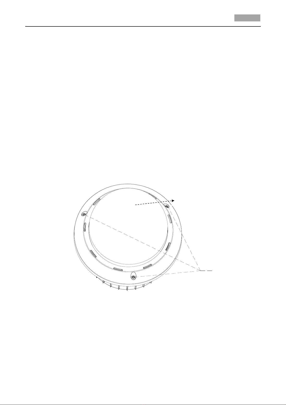
1.1.1
Installing the Speed Dome ............................................................................................................................... 1
1.1.2
Connecting the Cables ..................................................................................................................................... 6
1.2
DIP Switch Settings ............................................................................................................................................... 7
1.2.1
Address Settings ............................................................................................................................................... 8
1.2.2
Baudrate Settings ........................................................................................................................................... 10
1.2.3
Protocol Settings ............................................................................................................................................ 10
1.3
Alarm In/Out Connections ................................................................................................................................. 10
Chapte 2
Mount Int oduction ............................................................................................................................. 12
2.1
Wall Mount ........................................................................................................................................................ 12
2.2
Pendant Mount .................................................................................................................................................. 13
Chapte 3
Mounting Applications ........................................................................................................................ 14
3.1
Wall Mounting .................................................................................................................................................... 14
3.2
Pendant Mounting ............................................................................................................................................. 16
3.3
In-ceiling Mounting ............................................................................................................................................ 18
Appendix ..................................................................................................................................................................... 23
Appendix 1 Lightning & Surge Protection ....................................................................................................................... 23
Appendix 2 RS485 Bus Connection ................................................................................................................................. 24
Appendix 3 24VAC Wire Gauge & Transmission Distance .............................................................................................. 26
Appendix 4 Wire Gauge Standards ................................................................................................................................. 27