© 2018
Step 3 of 3
Order #XXXXX
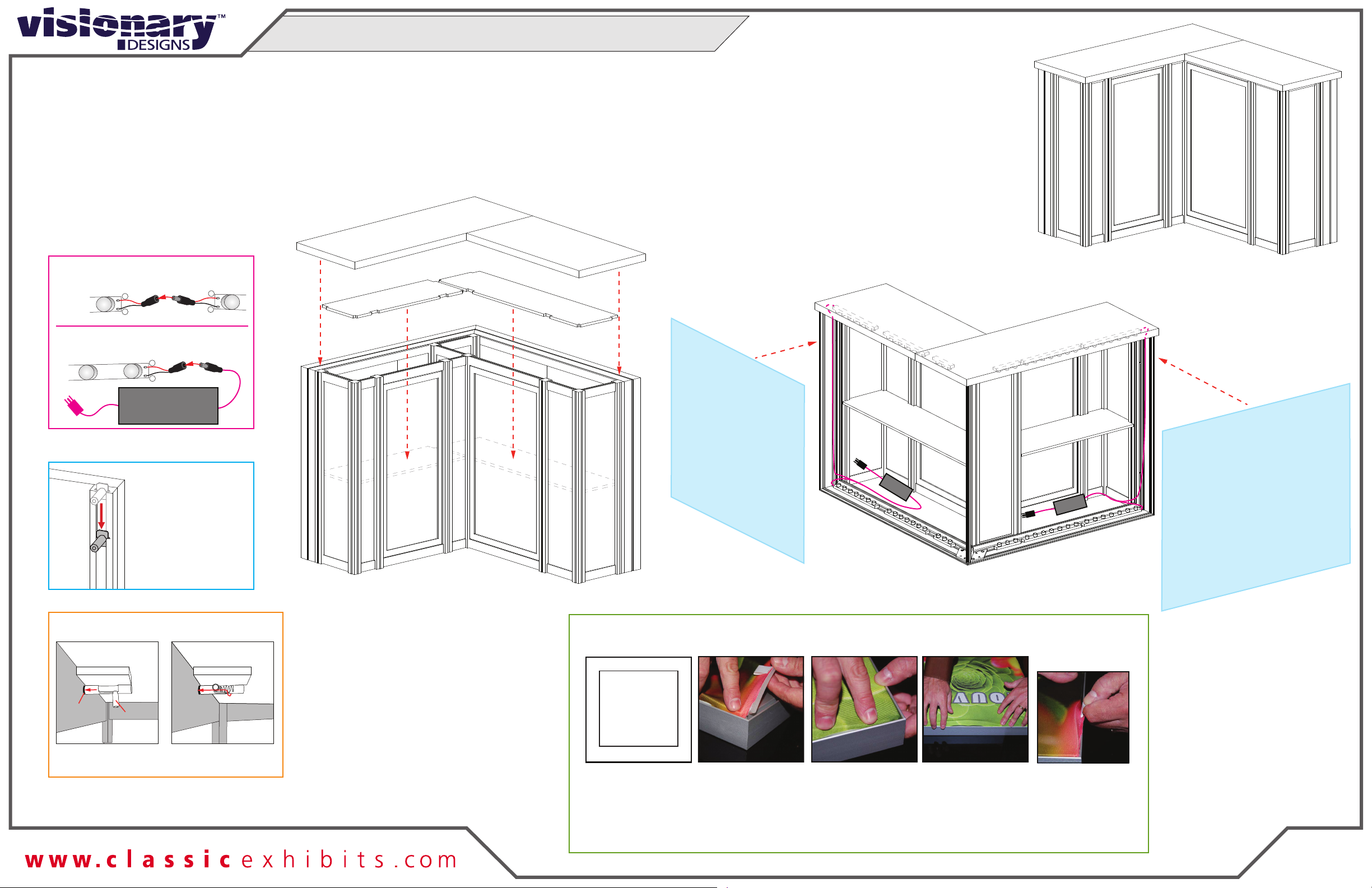
Completed Assembly
Back View
Counter Top
Counter Top
Shelf Shelf
Transformer Transformer
Steps:
1) Connect lighting power cords and attach
transformers. See Light to Light Connection
& Light to Transformer Connection details.
2) Place Shelves onto pins. See Shelf Pin detail.
3) Place Counter Top on top of assembed counter base.
See Counter Top Attachment detail.
4) Install SEG graphics to front of assembled frames.
See SEG Graphic Installation detail.
BACK VIEW FRONT VIEW
Graphic Removal
To remove the graphic from
the frame, locate the fabric
pull tab.Gently pull up on the
tab to remove the fabric.
Step 1
Insert corner A. Turn edge of
graphic so silicon welt is
perpendicular to face of
graphic. Insert narrow side
of welt with fabric to outside
into the channel. Repeat for
other side of this corner.
Step 2
Repeat Step 1 for opposite
corner C, then insert corner
B, followed by corner D, to
complete the installation of
the corners.
Step 3
Once all corners are inserted,
press one silicon edge into
channel from corners and
work toward the center.
Make sure welt is fully inserted
into channel. Continue until
all sides are done. Smooth
out edges of graphic.
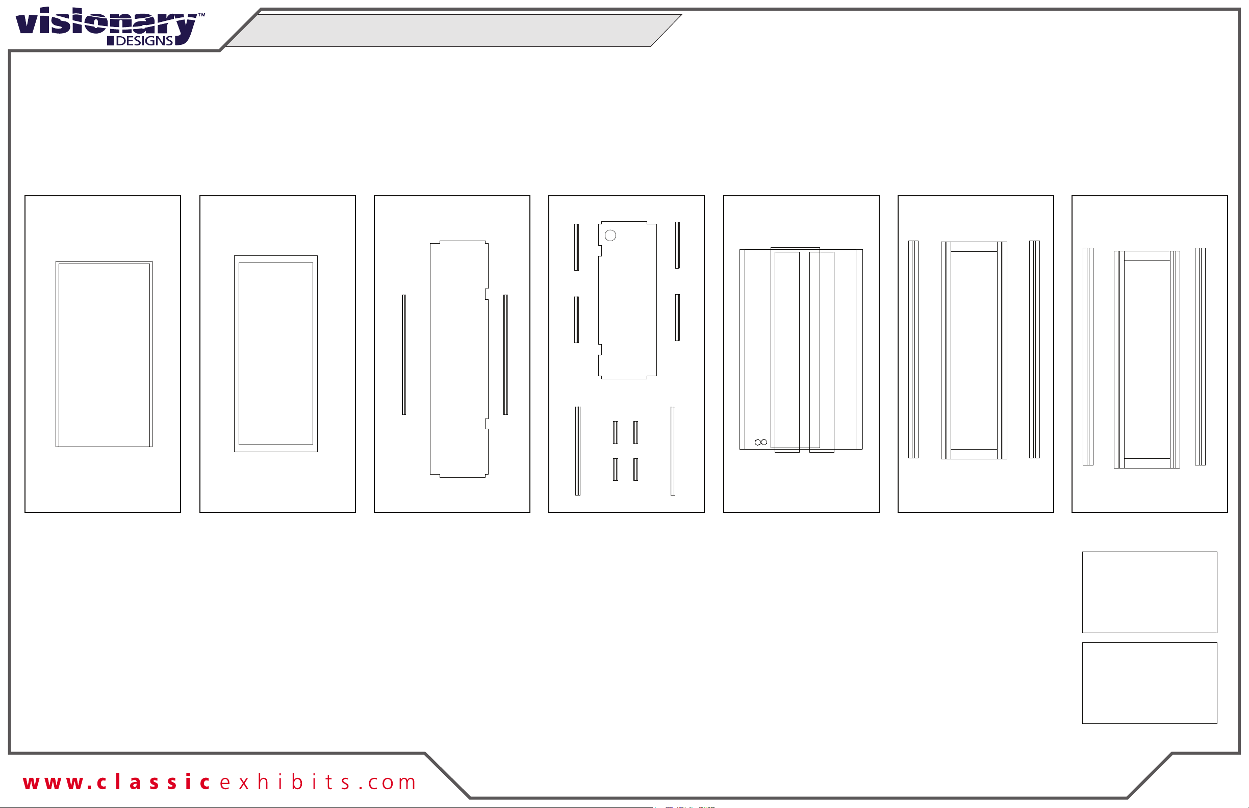
SEG Graphic Installation
It is important to first insert
graphic into each alternate
corner then to the sides of
the frame. If this is not done,
graphic will not fit into the
frame correctly.
Corner A
Corner D
Corner B
Corner C
***
**
*
**
SE
G Gra
p
h
i
c
S
E
G
G
raph
ic
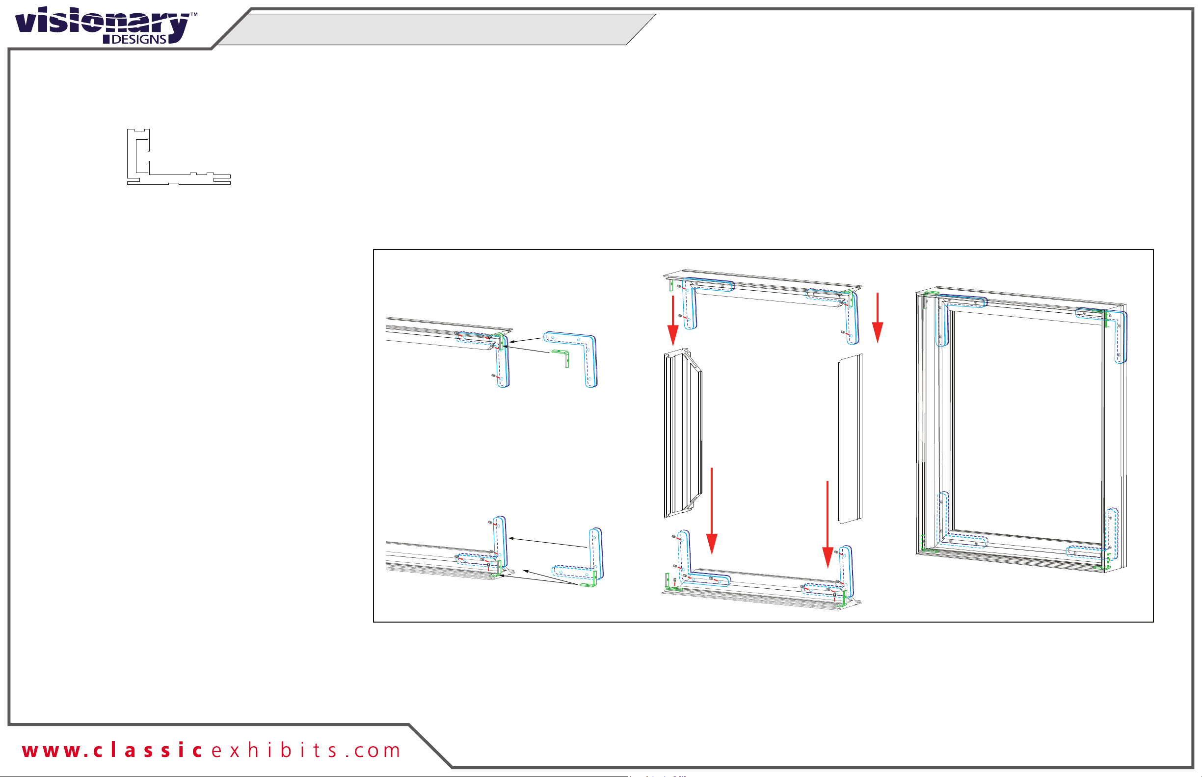
Shelf Pin
1) Slide pin into groove
of Vertical Extrusion.
2) Use hex tool to
tighten pin in place.
Pin
*
Align hole with pin Rotate pin. Spring
will push pin into hole.
Counter Top Attachment
12
*
Pin
Hole
++
+
-
-
-
to power
Lights
Male
Male
Female
Female
Transformer
Light to Light Connection
Light to Tranformer Connection
Counter Attachments (Cont’d)