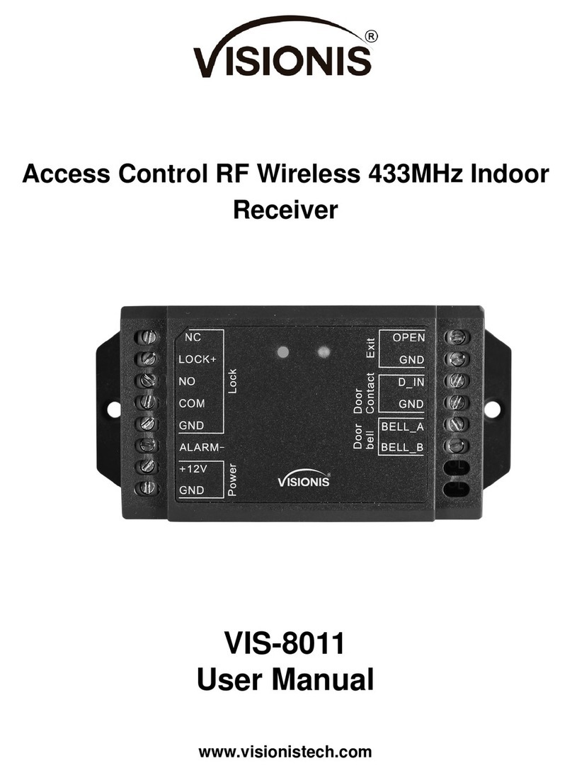
Visionis VIS-8011 User manual

Access Control RF Wireless 2.4GHz Indoor
Receiver
VIS-8011 / VIS-8012
User Manual

Specifications
Operating Voltage
Mini Controller
12V DC ±20%
Current
Idle Current
Working Current
≤20uA
≤40mA
Communication Frequency
2.4G
Communication Distance
15m Maximum (50 feet)
Relay Contact Load
2Amp Maximum
Environment
Operating Temperature
Operating Humidity
Indoor
-20°C~60°C (-4°F~140°F)
0%~86%RH
Physical
Dimensions
Unit Weight
ABS Shell
65L × 54W × 19D (mm) - 2.55L x 2.12W x 0.74D (in.)
40g
INSTALLATION
Method 1: Stick by 3M stickers
The device packed with 3M double-side Sticker, can easily stick the Mini Controller on Metal door, Glass Door, Wooden
Door, or Smooth Wall.
Method 2: Install by screws

Connection Diagram
Common Power Supply:
PROGRAMMING
Enter and Exit Program Mode
Programming Step
Keystroke Combination
1. Enter Program Mode
* (Master Code) #
(Factory default is 123456)
2. Exit
*
Set Master Code
Programming Step
Keystroke Combination
1. Enter Program Mode
* (Master Code) #
2. Update Master Code
0(New Master Code)#(Repeat New
Master Code)#
Master code is any 6 digits
3. Exit
*
Add User PIN(s)
User ID: 0~499
PIN length: 4~8 digits

Programming Step
Keystroke Combination
1. Enter Program Mode
* (Master Code) #
2. Add PIN
1 (User ID) # (PIN) # (Repeat PIN) #
The PINs can be added continuously
3. Exit
*
Add User Card(s)
User ID: 0~499
Card type: 125 KHz EM card
Programming Step
Keystroke Combination
1. Enter Program Mode
*(Master Code) #
2. Add Card: Using Auto ID
(Allows VIS-3200 to assign Card to next
available User ID number)
OR
2. Add Card: Select Specific ID
(Allows Master to define a specific User ID to
associate the card to)
1 (Read Card) #
The cards can be added continuously.
1 (User ID) # (Read Card) #
3. Exit
*
Change PIN Users
Programming Step
Keystroke Combination
Note: Below is done outside programming mode, users can undertake this themselves
2. Change PIN: By Card
(There will auto allocate PIN(8888) to cards
when adding)
* (Read Card) (Old PIN) # (New PIN) # (Repeat New
PIN) #
2. Change PIN: By PIN
* (User ID) # (Old PIN) # (New PIN) # (Repeat New
PIN) #
3. Exit
Exit automatically
Delete Users
Programming Step
Keystroke Combination
1. Enter Program Mode
* (Master Code) #
2. Delete user
OR
2. Delete Card
OR
2. Delete all users
2 (User ID) #
The users can be deleted continuously
2 (Read Card) #
2 (Master Code) #
3. Exit
*

Set Access Mode
Programming Step
Keystroke Combination
1. Enter Program Mode
* (Master Code) #
2. PIN Access
OR
PIN + Card Access
OR
PIN or Card Access
3 0 #
3 1 #
3 2 # (factory default)
3. Exit
*
Set Relay Configuration
The relay configuration sets the behavior of the output relay on activation.
Programming Step
Keystroke Combination
1. Enter Program Mode
*(Master Code) #
2. Pulse Mode
OR
2. Toggle Mode
4 (1-99) # (factory default)
The relay time is 1-99 seconds. (1 is 50mS.)
(Default is 5 seconds)
4 0 #
Set the relay to ON/OFF Toggle mode
3. Exit
*
Set Safety Mode
In safety mode, it can be set to deny access for 10 minutes after 10 failed PIN/card attempts in 10 minutes
(Factory default is OFF).
Programming Step
Keystroke Combination
1. Enter Program Mode
*(Master Code) #
2. Strike-Out OFF
OR
2. Strike-Out ON
6 0 # (factory default)
6 1 #
3. Exit
*
Set Buzzer
Programming Step
Keystroke Combination
1. Enter Program Mode
*(Master Code) #
2. Buzzer OFF
OR
2. Buzzer ON
7 0 #
7 1 # (factory default)
3. Exit
*

OTHERS
Users Operation
Programming Step
Keystroke Combination
PIN User Access
(PIN) #
Card User Access
# (Read Card)
PIN + Card User Access
# (Read Card) (PIN) #
Pair Wireless Keypad / Exit Button and Mini Controller
1) They all are already paired when out of factory, if no problem, the users do not need to do this operation in using.
2) One Mini Controller can be connected by five pcs of Wireless Keypad and Exit Button maximum.
To pair the Wireless Keypad and Mini Controller:
Wireless Keypad: * Master Code # 9 0 #
Mini Controller: Remove the back cover, and press the button “Pair”
If pair successfully, there will be one beep from both the controller and the keypad; if not, there will be three short beeps,
then please repeat the setting. The keypad does not need to be entered * for exit in this step.
To pair the Wireless Exit Button and Mini Controller:
Wireless Exit Button: Remove the back cover, and press the button “Pair”
Mini Controller: Remove the back cover, and press the button “Pair”
If pair successfully, there will be one beep from both the controller and the exit button; if not, there will be three short beeps,
then please repeat the setting.
Pair two pcs of Wireless Keypad and Mini Controller---Optional
(This is optional solution for users, the extra wireless keypad Does Not included in the packing list)
Wireless Keypad 1: * Master Code # 9 0 #
Wireless Keypad 2: * Master Code # 9 0 #
Mini Controller: Remove the back cover, and press the button “Pair”
If pair successfully, there will be one beep from both the controller and the keypads; if not, there will be three short beeps,
then please repeat the setting. The keypads does not need to be entered * for exit in this step.
Reset to Factory Default
Open the back cover of the wireless keypad, press the button “RST” on the main board, hold it for 5 seconds, release it
until hear a long beep, means reset to factory default successfully.
After that, all settings except the relay time will be back to factory defaults, the users’ information will still be retained.
At the meanwhile, please pair the wireless keypad and wireless exit button with the mini controller again.

VIS-8011 / VIS-8012 - Simplified Instruction
Function description
Operation
Enter the Program Mode
* (123456) #
then you can do the programming
(123456 is the factory default master code)
Change the Master Code
0 (New Code) # (Repeat the New Code) #
(Code: 6 digits)
Add PIN User
1 (User ID) # (PIN) # (Repeat PIN) #
Add Card User
1 (Read Card)
Delete User
2 (User ID) #
2 (Read Card)
Exit from the Program Mode
*
How to release the door
PIN Access
PIN #
Card Access
# (Read Card)
PIN + Card Access
# (Read Card) (PIN) #
Note: there is a battery spacer inside the Wireless Exit Button, please take it off before operation.
This manual suits for next models
1
Table of contents
Other Visionis Receiver manuals
