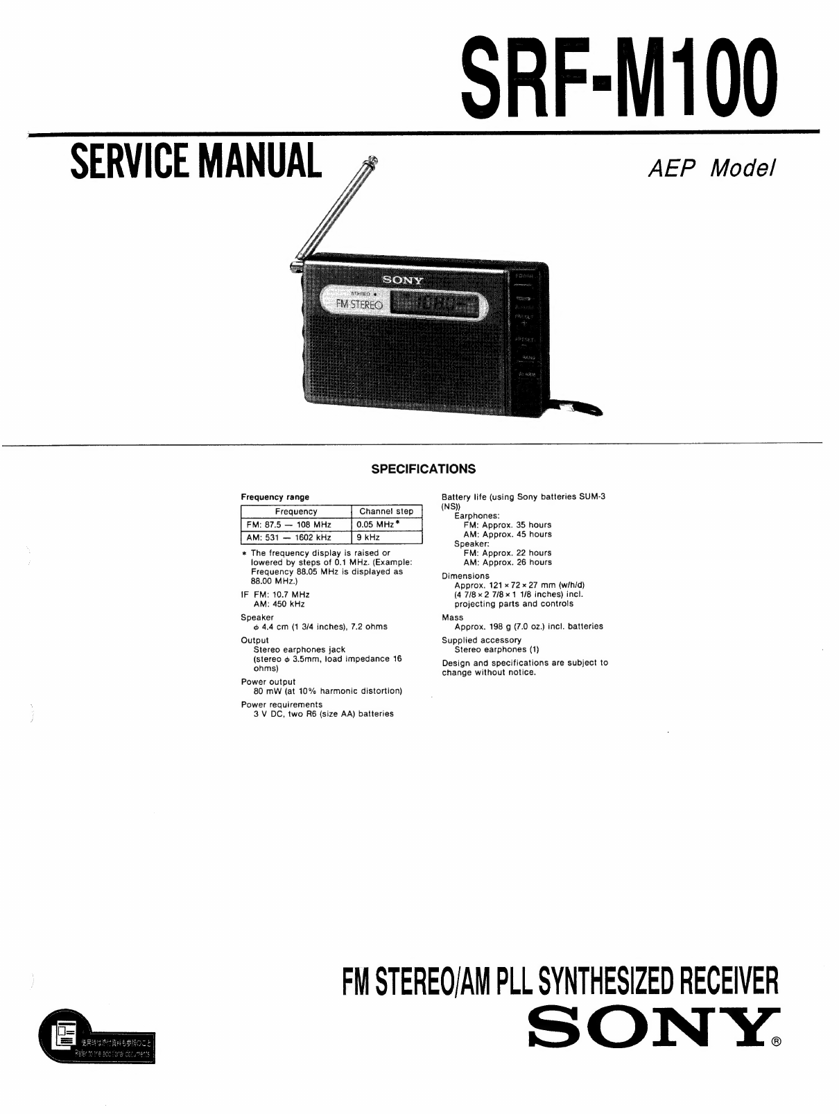
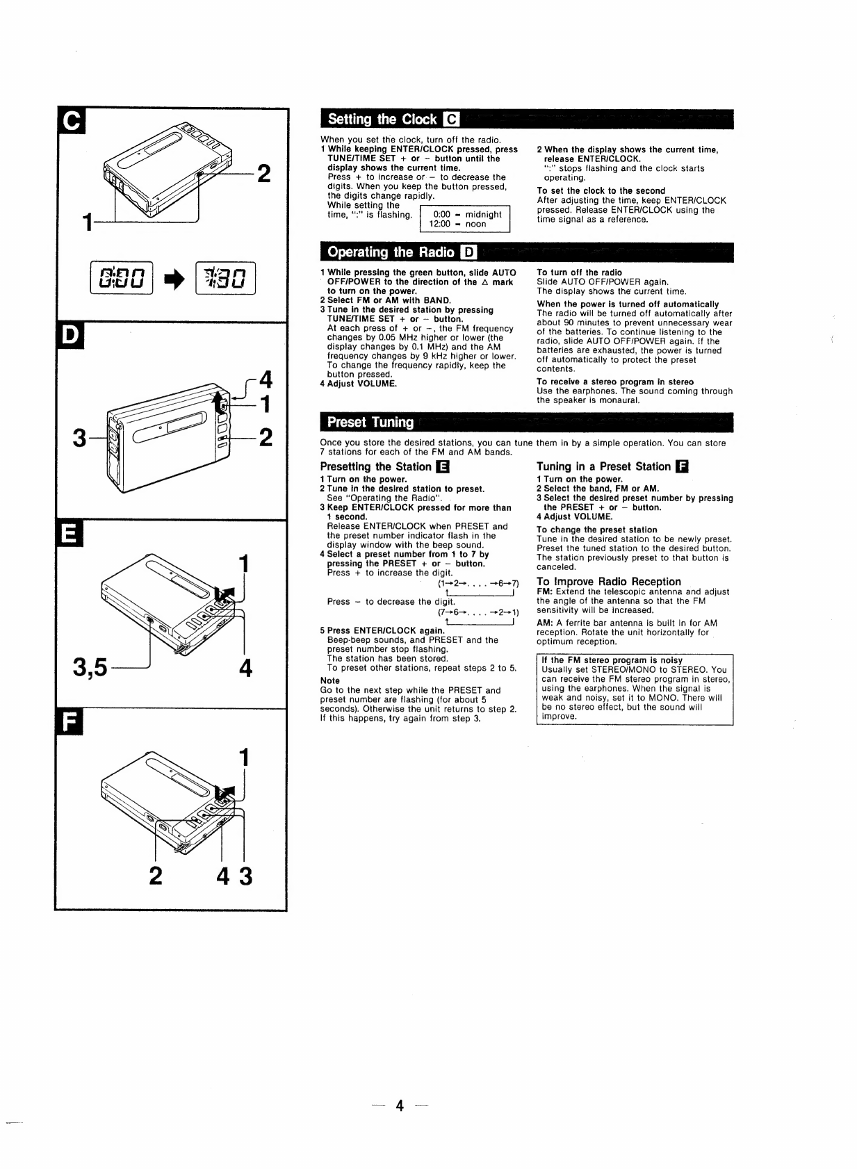
Sony SRF-M100 User manual

SERVICE
MANUAL
SRF-M100
AEP
Model
SPECIFICATIONS
Frequency
range
FM:
87.5
—
108
MHz
0.05
MHz*
AM:
531
—
1602
kHz
*
The
frequency
display
is
raised
or
lowered
by
steps
of
0.1
MHz.
(Example:
Frequency
88.05
MHz
is
displayed
as
88.00
MHz.)
IF
FM:
10.7
MHz
AM:
450
kHz
Speaker
4.4
cm
(1
3/4
inches),
7.2
ohms
Output
Stereo
earphones
jack
(stereo
¢
3.5mm,
load
impedance
16
ohms)
Power
output
80
mW
(at
10%
harmonic
distortion)
Power
requirements
3
V
DC,
two
R6
(size
AA)
batteries
Battery
life
(using
Sony
batteries
SUM-3
(NS))
Earphones:
FM:
Approx.
35
hours
AM:
Approx.
45
hours
Speaker:
FM:
Approx.
22
hours
AM:
Approx.
26
hours
Dimensions
Approx.
121
x
72
x
27
mm
(wih/d)
(4
7/8
x
2
7/8
1
1/8
inches)
incl.
projecting
parts
and
controls
Mass
Approx.
198
g
(7.0
02.)
incl.
batteries
Supplied
accessory
Stereo
earphones
(1)
Design
and
specifications
are
subject
to
change
without
notice.
FM
STEREO/AM
PLL
SYNTHESIZED
RECEIVER
SONY.

TABLE
OF
CONTENTS
Section
Title
Page
Specifications
eee
ee
ee
eee
eee
ray
]
1.
GENERAL
Location
of
Controls
eee
eee
ee
ee
ee
rr
ey
3
Installing
Batteries
eee
eee
i
ee
iris
3
Setting
the
Clock
eee
eee
ee
ee
ee
eee
ee
ee
ee
i
ee
ee
ee
ir
4
Operating
the
Radio
ee
er
er
er
ee
rir
4
Preset
Tuning
ORD
e
eee
meee
ed
memes
eee
ene
eee
eens
eee
eee
eenesenensneeere
4
Sound
the
Beep
at
a
Desired
Time
Cem
e
nme
re
cerns
enanseceeesseureens
5
9.
‘DISASSEMBLY
si
essnseciessdce
cents
nai
vvsen
eatavactorsenaeeys
6
3.
PIN
DESCRIPTION:
--:--cceeccesceccceeccsccscessceecescenecoeeees
7
4.
ELECTRICAL
ADJUSTMENTS
-oeeesesseseeeeeeerseeeeeeereees
9
5.
DIAGRAMS
5-1.
Printed
Wiring
Boards
<srrrrsseeessereeeeeeeeeeereeneeeneees
14
5-2.
Schematic
Diagram
deem
e
mene
n
eer
etennneee
see
eeeserenesenenes
17
6.
EXPLODED
VIEW
iisicsecsnesecnsiaiieas
shevecdeerceresnareanneans
21
7.
ELECTRICAL
PARTS
LIST
---------eeesseersrereeeeeseee
rene
ae
Flexible
Circuit
Board
Repairing
@®
Keep
the
temperature
of
the
soldering
iron
around
270°C
during
repairing.
@
Do
not
touch
the
soldering
iron
on
the
same
conduc-
tor
of
the
circuit
board
(within
3
times).
®@
Be
careful
not
to
apply
force
on
the
conductor
when
soldering
or
unsoldering.
Notes
on
chip
component
replacement
@
Never
reuse
a
disconnected
chip
component.
@
Notice
that
the
minus
side
of
a
tantalum
capacitor
may
be
damaged
by
heat.

SECTION
1
GENERAL
Front
panel
Rear
panel
Display
window
(Ob.E
Reverv
eye)
meal
ie
cam
A
|
STEREO
indicator
Lights
when
a
stereo
program
is
received.
[2]
Display
window
Speaker
[4]
ENTER/CLOCK
button
[5]
TIMER
button
BAND
selector
ALARM
button
AUTO
OFF/POWER
switch
[9]
VOLUME
control
PRESET
+
and
—
buttons
PHONES
(stereo
earphones)
jack
2
Earphones
Extend
the
earphone
cord
as
it
serves
as
the
FM
antenna.
By
disconnecting
the
earphone
cord,
the
sound
is
heard
from
the
speaker.
The
sound
coming
through
the
speaker
is
monaural.
eIae)
STEREO/MONO
(stereo/monaural)
selector
.
TUNE
(tuning)/TIME
SET
+
and
—
buttons
Battery
compartment
Telescopic
antenna
Extend
the
telescopic
antenna
as
illustrated.
Battery
indicator
Flashes
when
the
batteries
become
weak,
Alarm
indicator
Appears
when
you
set
the
alarm.
Timer
indicator
Appears
when
you
set
the
timer.
Frequency
indicator
Appears
while
the
radio
is
on.
Band
indicator
[22]
PRESET
and
preset
number
indicators
Time
indicator
Appears
when
the
radio
is
off.
This
section
is
extracted
from
instruction
manual.
Two
R6
(size
AA)
batteries
with
correct
polarity
Installing
Batteries
EJ
insert
two
R6
(size
AA)
batteries
with
correct
polarity.
When
you
insert
the
batteries
for
the
first
time,
0:00
flashes
in
the
display
window.
To
stop
flashing,
press
ENTER/CLOCK.
Knowing
when
to
replace
the
batteries
When
the
batteries
become
weak,
the
radio
is
turned
off,
the
time
indicator
appears
and
“cq”
flashes
in
the
display
window.
(The
sound
may
become
weak
or
distorted
before
“‘csa”
starts
flashing.)
Replace
both
batteries
with
new
ones.
Even
after
you
replace
the
batteries,
“cosa”
remains
flashing.
To
turn
off
“cs”,
slide
AUTO
OFF/POWER.
Replace
the
batteries
within
about
60
seconds
after
turning
off
the
power.
If
more
than
60
seconds
has
passed,
the
preset
stations
are
canceled
and
the
time
indicator
shows
0:00.
In
this
case,
perform
the
clock
setting
and
preset
tuning
again.
Notes
on
the
battery
¢
Insert
the
batteries
with
correct
polarity.
*
Do
not
mix
new
and
used
batteries.
e
The
batteries
cannot
be
charged.
*
To
avoid
damage
from
possible
battery
leakage,
remove
the
batteries
when
the
unit
will
not
be
used
for
a
long
time.
*
Concerning
the
battery
life,
see
“Specifications”.
Se
ET

Setting
the
Clock
When
you
set
the
clock,
turn
off
the
radio.
1
While
keeping
ENTER/CLOCK
pressed,
press
TUNE/TIME
SET
+
or
—
button
until
the
display
shows
the
current
time.
Press
+
to
increase
or
—
to
decrease
the
digits.
When
you
keep
the
button
pressed,
the
digits
change
rapidly.
While
setting
the
time,
“:"
is
flashing.
0:00
=
midnight
12:00
=
noon
2
When
the
display
shows
the
current
time,
release
ENTER/CLOCK.
“?"
stops
flashing
and
the
clock
starts
operating.
To
set
the
clock
to
the
second
After
adjusting
the
time,
keep
ENTER/CLOCK
pressed.
Release
ENTER/CLOCK
using
the
time
signal
as
a
reference.
eee
ule
Mm
UC
Mteleom
D
|
2
1
While
pressing
the
green
button,
slide
AUTO
’
OFF/POWER
to
the
direction
of
the
A
mark
to
turn
on
the
power.
2
Select
FM
or
AM
with
BAND.
3
Tune
in
the
desired
station
by
pressing
TUNE/TIME
SET
+
or
—
button.
At
each
press
of
+
or
—,
the
FM
frequency
changes
by
0.05
MHz
higher
or
lower
(the
display
changes
by
0.1
MHz)
and
the
AM
frequency
changes
by
9
kHz
higher
or
lower.
To
change
the
frequency
rapidly,
keep
the
button
pressed.
4
Adjust
VOLUME.
To
turn
off
the
radio
Slide
AUTO
OFF/POWER
again.
The
display
shows
the
current
time.
When
the
power
is
turned
off
automatically
The
radio
will
be
turned
off
automatically
after
about
90
minutes
to
prevent
unnecessary
wear
of
the
batteries.
To
continue
listening
to
the
radio,
slide
AUTO
OFF/POWER
again.
If
the
batteries
are
exhausted,
the
power
is
turned
off
automatically
to
protect
the
preset
contents.
To
receive
a
stereo
program
in
stereo
Use
the
earphones.
The
sound
coming
through
the
speaker
is
monaural.
Preset
Tuning
Once
you
store
the
desired
stations,
you
can
tune
them
in
by
a
simple
operation.
You
can
store
7
stations
for
each
of
the
FM
and
AM
bands.
Presetting
the
Station
[4
1
Turn
on
the
power.
2
Tune
in
the
desired
station
to
preset.
See
“Operating
the
Radio”.
.
3
Keep
ENTER/ICLOCK
pressed
for
more
than
1
second.
Release
ENTER/CLOCK
when
PRESET
and
the
preset
number
indicator
flash
in
the
display
window
with
the
beep
sound.
4
Select
a
preset
number
from
1
to
7
by
pressing
the
PRESET
+
or
—
button.
Press
+
to
increase
the
digit.
(12>...
.
+67)
to
Press
—
to
decrease
the
digit.
(7>6—>.
..
.
-*2->1)
|
eae
ee
ee
5
Press
ENTER/CLOCK
again.
Beep-beep
sounds,
and
PRESET
and
the
preset
number
stop
flashing.
The
station
has
been
stored.
To
preset
other
stations,
repeat
steps
2
to
5.
Note
Go
to
the
next
step
while
the
PRESET
and
preset
number
are
flashing
(for
about
5
seconds).
Otherwise
the
unit
returns
to
step
2.
If
this
happens,
try
again
from
step
3.
Tuning
in
a
Preset
Station
jj
1
Turn
on
the
power.
2
Select
the
band,
FM
or
AM.
3
Select
the
desired
preset
number
by
pressing
the
PRESET
+
or
—
button.
4
Adjust
VOLUME.
To
change
the
preset
station
Tune
in
the
desired
station
to
be
newly
preset.
Preset
the
tuned
station
to
the
desired
button.
The
station
previously
preset
to
that
button
is
canceled.
To
Improve
Radio
Reception
FM:
Extend
the
telescopic
antenna
and
adjust
the
angle
of
the
antenna
so
that
the
FM
sensitivity
will
be
increased.
AM:
A
ferrite
bar
antenna
is
built
in
for
AM
reception.
Rotate
the
unit
horizontally
for
optimum
reception.
If
the
FM
stereo
program
is
noisy
Usually
set
STEREO/MONO
to
STEREO.
You
can
receive
the
FM
stereo
program
in
stereo,
using
the
earphones.
When
the
signal
is
weak
and
noisy,
set
it
to
MONO.
There
will
be
no
stereo
effect,
but
the
sound
will
improve.

Sounding
the
Beep
at
a
Desired
Time
You
can
make
the
unit
sound
its
beep
through
the
speaker
or
the
earphones
at
a
desired
time.
Use
this
feature
to
remind
you
of
an
appointment,
etc.
There
are
two
ways
of
setting:
¢
Timer
setting—to
sound
the
beep
a
certain
number
of
minutes
later
than
the
present.
e
Alarm
setting—to
sound
the
beep
at
a
certain
time.
You
can
set
the
timer
and
alarm
while
the
radio
is
either
on
or
off.
Setting
the
Timer
[ej
1
While
keeping
TIMER
pressed,
press
TUNE/TIME
SET
+
or—
button
to
store
the
desired
period
in
minutes
after
which
you
want
the
beep
to
sound.
You
can
store
periods
from
1
to
180
minutes
at
one
minute
intervals.
&)
flashes
in
the
display
window
while
you
press
TIMER.
To
sound
the
beep
after
30
minutes,
for
example,
while
keeping
TIMER
pressed,
press
TUNE/TIME
SET
+
or
—
until
30
appears
in
the
display
window.
2
Release
TIMER.
©)
stops
flashing.
The
display
returns
to
the
current
time
or
to
the
frequency
which
was
shown
before
you
-
pressed
TIMER
to
start
the
timer
setting.
When
the
stored
period
has
passed,
)
flashes
and
the
beep
sounds.
:
To
cancel
the
timer
setting
Press
TIMER
again.
&)
disappears.
To
stop
the
beep
Press
any
button.
If
you
do
not
stop
the
beep,
the
beep
stops
automatically
after
about
3
minutes.
When
the
beep
sounds
while
you
are
fistening
to
the
radio,
the
radio
reception
stops
and
resumes
when
the
beep
stops.
Setting
the
Alarm
[J]
Make
sure
that
the
clock
is
correctly
set.
(See
“Setting
the
Clock”.)
1
White
keeping
ALARM
pressed,
press
TUNE/TIME
SET
+
or
—
button
to
set
the
time
you
want
the
beep
to
sound.
)
flashes
while
you
press
ALARM.
To
set
the
alarm
for
7:00
in
the
morning,
for
example,
while
keeping
ALARM
pressed,
press
TUNE/TIME
+
or
—
until
7:00
appears
in
the
display
window.
2
Release
ALARM.
*)
stops
flashing.
The
display
returns
to
the
current
time
or
the
frequency
which
was
shown
before
you
pressed
ALARM
to
start
the
alarm
setting.
When
the
time
comes,
()
flashes
and
the
beep
sounds.
To
cancel
the
alarm
setting
Press
ALARM
again.
()
disappears.
To
stop
the
beep
Press
any
button.
If
you
do
not
stop
the
beep,
the
beep
stops
automatically
after
about
3
minutes.
When
the
beep
sounds
while
you
are
listening
to
the
radio,
the
radio
reception
stops
and
resumes
when
the
beep
stops.
Notes
e
When
0:00
flashes,
you
cannot
set
the
alarm.
e
When
you
stop
the
beep,
the
timer
setting
is
canceled.
The
alarm
setting
remains.
*
Even
if
you
are
listening
to
radio,
you
can
set
the
timer
and
alarm.

SECTION
2
DISASSEMBLY
Note
:
Follow
the
disassembly
procedure
in
the
numerical
order
given.
2-1.
CABINET
(REAR)
2-3.
MAIN
BOARD
4+B2
x
8
@
+82x6
ees
x
Battery
case
¢
7
@+B2x8
™%
:
é
}
f
PEA
©
Cabinet
(Rear)
‘
as
©
Press
the tab
as
YY
shown
by
the
arrow.
i
N
aS
©
Insert
a
flat-tipped
screwdriver
in
the
groove
between
the
front
cabinet
and
,
4)
Pies
ie
tab
es
SHOW
Dy
Meow,
the
rear
cabinet
to
open.
2-2.
CABINET
(FRONT)
2-4.
MICROCOMPUTER
BOARD
@
+826
-
@
+82
x6
Microcomputer
board
@
Press
the tab
as
shown
by
the
arrow.

SECTION
3
PIN
DESCRIPTION
Pin
description
of
4
PD1724GB-555-1A7
(IC101)
LCD
drive
segment
signal
output.
Pin
number
-[2
pe
>)
ea
—
Mm
__
ON
APN
owo
re
i
bdo
LCD
drive
common
signal
output
—
be
—_
al
VSS3
CAP2
CAP1
CGP
BUZZER
16
Terminals
used
for
connecting
a
capacitor
of
a
doubler
circuit
which
supplies
LCD
17
drive
voltage.
18
VSS2
Audio
mute
output
signal.
Active
when
Low.
Audio
noises
are
reduced
before
and
after
the
mute
signal
when
PLL,
radio
power
supply
or
key
srtobe
change
is
controlled.
Buzzer
output
using
CGP.
Sound
to
check
keys,
to
check
settings,
to
indicate
that
a
setting
time
of
timer
is
reached
or
to
alarm
is
produced
by
using
two
kinds
of
musical
intervals
and
the
sound
modulation.
nN Oo
pels!
ie)
D
D
VCOH
VHF
VCOM
FM
VCO
25
VCOL
AM
VCO
26
VSS1
VSS1
27
EOI
EO1
Ea
Not
use
with
this
machine.
28
EO2
EQ2
5V
power
supply
input
terminal.
NY
0
<
i)
23
24
Detects
the
voltage
reduction
of
the
AC
battery.
When
the
battery
energy
is
reduced,
the
microcomputer
is
in
the
reducedvoltage
mode.
The
battery
mark
blinks
and
the
microcomputer
waits
for
a
clock’s
reset/display
and
Power
ON
Key.
A
quartz
oscillating
element
connecting
terminal.
(75kHz)
Connected
to a
capacitor
for
a
regulator
circuit
which
supplies
the
oscillator’
stable
drive
voltage.
Time
display
switching
input.
It
is
a
24-hour
system
display
when
Low
and
a
12-hour
system
display
(AM/PM)
when
High.
When
the
setting
is
changed,
backup
power
supply
must
be
set
to
OFF
and
internal
RAM
must
be
initialized.
ON/OFF
switching
output
for
the
radio
power
supply.
(ON
:
High
,
OFF
:
LOW)
Strobe
output
for
initial
switch
input.
INIT
OUT
(Active
:
High)
o——+
INITIN
1:
12-/24-hour
system
display
LOW
(OFF)
:
24-hour
system
display,
Hgih
(ON)
:
12-hour
system
dispaly
o——»>
INIT
IN
2:
Band
selection
Not
use
with
this
machine.
pe
o
ies)
le
eg
30
31
XI
XO
32
VSS4
VSS4
x
He
‘
OO Ww
Ww
PA3
INIT
IN1
Qo
KR
PA2
POWER
OUT
nS
PAI
INIT
OUT

number
1-bit
input
which
sets
two
kinds
of
receiving
band
versions.
When
the
setting
is
36
PAO
INIT
IN2
I
changed,
backup
power
supply
must
be
set
to
OFF
and
internal
RAM
must
be
initialized.
Cas
[i
BEEP
Vol
BEEP
volume.
Output
for
increasing
the
volume
of
the
BEEP
sound
when
a
setting
time
of
timer
is
reached
or
an
alarm
is
ON.
The
volume
is
increased
when
high.
ten
aca
(50
ct
ane
ER
Pap
Pe
Key
SOURCE
a
K3
7
|
Key
RETURN
I
48
KO
1-bit
output
which
sets
two
kinds
of
receiving
bands.
Two
settings
are
as
followes.
AM=H,
FM=L,
POWER
OFF
:
L
Strobe
and
return
signals
in
3
X
4 key
matrix.
A
strobe
signal
change
makes
an
audio
noise.
A
strobe
signal
must
be
set
to
the
fixed
value
when
a
key
input
is
not
changed.
When
the
key
input
is
decoded,
the
mute
signal
must
be
added.

SECTION
4
ELECTRICAL
ADJUSTMENTS
©
Be
sure
to
perform
a
AM
tracking
adjustment
after
having
made
a
AM
frequency
coverage
adjustment.
Setting:
BAND
SW
:
AM
STEREO
/MONO
SW
:
MONO
AM
PF
signal
generator
Put
the
jead-wire
VA
antenna
close
to
the
set.
Cd
Phones
jack
30%
amplitude
modulation
by
400Hz
Signal.
Output
level
:
as
low
as
possible.
AM
IF
Adjustment
Procedure
:
1.
Set
the
frequency
of
the
set
and
RF
SSG
at
531
KHz.
2.
Adjust
T1
so
that
the
reading
of
VTVM
becomes
maximum.
3.
Refer
to
the
diagram
below
for
the
final
characteristics.
ae
(final
characteristics)
T1
{MAIN
BOARD
(Conductor
side)]
{MAIN
BOARD
(Component
side))
digital
voltmeter
AM
Frequency
Coverage
Adjustment
AM
Tracking
Adjustment
Procedure
:
Procedure
:
1.
Set
the
frequency
of
the
set
and
RF
SSG
at
531kHz.
1,
Set
the
frequency
of
the
set
and
RF
SSG
at
585kHz.
2.
Adjust
LS
so
that
the
voltage
between
TP4
and
the
2.
Adjust
L1
so
that
the
reading
of
VTVM
becomes
ground
becomes
|
+
0.05V.
maximum.
3.
Set
the
frequency
of
the
set
and
RF
SSG
at
1,602kHz.
3.
Set
the
frequency
of
the
set
and
RF
SSG
at
1,485kHz.
4,
Adjust
CT3
so
that
the
voltage
between
TP4
and
the
4.
Adjust
CT1
so
that
the
reading
of
VTVM
becomes
ground
becomes
7.3
+
0.05V.
maximum.
5.
Repeat
the
adjusting
steps
above
two
or
three
times.
@
Terminate
the
AM
tracking
adjustment
by
adjusting
the
trimmer
capacitor.

@
Be
sure
to
perform
a
FM
tracking
adjustment
after
having
FM
Frequency
coverage
and
Taking
Adjustment
Setting:
BAND
SW
:
FM
STEREO
/MONO
SW
:
MONO
VTVM
FM
PF
signal
generator
Phones
jack
(CJ
22.5kHz,
frequency
deviation
by
400
Hz
signal.
Output
level
:
as
low
possible
digital
voltmeter
(MAIN
BOARD
(Component
side)]
FM
Frequency
Coverage
Adjustment
Procedure
:
1.
Set
the
frequency
of
the
set
and
RF
SSG
at
108.0MHz.
2.
Adjust
L4
so
that
the
voltage
between
TP4
and
the
ground
becomes
9.5
+
1.5V.
made
a
FM
frequency
coverage
adjustment.
(MAIN
BOARD
(Conductor
side)]
FM
Tracking
Adjustment
Procedure
:
1.
Set
the
frequency
of
the
set
and
RF
SSG
at
87.5MHz.
2.
Adjust
L2
so
that
the
reading
of
VTVM
becomes
maximum.
3.
Set
the
frequency
of
the
set
and
RF
SSG
at
108.0MHz.
4,
Adjust
CT2
so
that
the
reading
of
VTVM
becomes
maximum.
5.
Repeat
the
adjusting
steps
above
two
or
three
times.
@
Terminate
the
FM
tracking
adjustment
by
adjusting
the
trimmer
capacitor.

FM
VCO
Adjustment
Setting:
BAND
SW
:
FM
STEREO
/MONO
SW
:
STEREO
FM
FF
signal
generator
0.01
uF
Cr]
22.5kHz,
frequency
deviation
by
400
Hz
signal.
Output
level
:
as
low
possible
{MAIN
BOARD
(Componen
Procedure
:
@
Be
sure
to
perform
a
FM
VCO
adjustment
after
having
made
a
FM
frequency
coverage
adjustment.
[MAIN
BOARD
(Conductor
side)]
t
side)]
RVI
Ll
FERRITE-R00
ANTENNA
Frequency
counter
+0
1.
Set
the
frequency
of
the
set
and
RF
SSG
at
108.0MHz.
2.
Adjust
RV1
for
76kHz
+
200Hz
reading
on
frequency
counter.


SRF-M100
5-1.
PRINTED
WIRING
BOARDS
SECTION
5
rN
A
tt
eS
(MAIN
BOARD]
(comPoNeENT
SIDE)
DIAGRAMS
@
SEMICONDUCTOR
LOCATION
©
SEMICONDUCTOR
LEAD
LAYOUTS
(MAIN
BOARD]
(conpuctor
SIDE)
ANTI
FM
TELESCOPIC
ANTENNA
——
S-8052
ANB-NE-S
IT33
e
Z
ae
te
er
Nr
eae
RE
Lt
FERRITE-ROD
ANTENNA
Vss
=
GRRE
Voo
Output
PD1724GB-555-1A7
AMSA
SMS
765
°
.
s
Ff
°
234
(Marking
side
view)
a
MA152WK
28A1162-G
Sie
1
Sas
2SC1623-L5L6
:
he
‘
28C4177
;
i
:
28C4178-F14
sa
i
e
DTA144EK
anode
@
(Os
DTA144TK
anode
J
DTC144EK
|
[PHONES
|
DTC144TU
Sg
RSA
USSR,
:
ee
ee
—
eC
1-
640-905"
RD13M-B2
1—
640-905
-
a
a
’
ES
ja
ks
SPI
Hen
ae
”
ou
SPEAKER
LIQUID
CRYSTAL
DISPLAY
PANEL
Creme
R6
2PCS,
3V
$109
Sil0
“
[MICROCOMPUTOR
BOARD]
(component
sive)
FLEXIOLE.oRRD
|
2SK209-G
203
1
SE
SSE
CB
SSN
ee
$101
SERN
SS
SR
eR
HE
8
LSE
A
RNR
RE
LCDI
fr
yumm
\ioncneenonpannnell
LIQUID
_CRYSTAL_DISPLAY_PANEL
[MICROCOMPUTOR
BOARD]
(conductor
SIDE)
1SS226
,
—
nem
“
3
&
2
XN4608
231
2
3
PR243D
HL
:
.
DAN202U
HE
gue
@
SS
:
2 :
cathode
Note:
anode
ia
ane
*
O—-:
parts
extracted
from
the
component
side.
ia
*
Es:
parts
mounted
on
the
conductor
side.
*
@
:
Through
hole.
$106
POWER
(AUTO
OFF)
:
Pattern
on
the
side
which
is
seen.
:
Chip
components
extracted
from
the
rear
side.
02
SS
=
14
tS
—
16
—

SRF-M100
5-2.
SCHEMATIC
DIAGRAM
27
1
2
3
4
5
6
7
8
9
10
11
12
__
13
14
15
16
17
18
19
20
21
22
23
24
25 26
©
WAVEFORMS
[MAIN
BOARD]
314nsec
———>|
A
Ree
ca
189k
1133-78-08
Ql
ANT
|
“
2804178
—FI3FI4
FM
TELESCOPIC
BUFFER
ANTENNA
65
D4
;
rg
3
3
B+
’
;
;
Eg
[B+
i
—______
Set
__
B+
£8,
1
css
=e
3
7?
27yH
Fy
3
i
i
.
c29
|+
m0
c26
|
+
RB
1.3
7
ale
(om
|
220
30
a
CXAISZ2M
earlé
B
15k
io
ta
av
6.1
POWER
AM
’
gat
c42
|
ly
4v
.
LA3335M
0.1
ee
CX20111
,
eu
MeK
oO}
V
cu
I
0.3
FM/AM
FRONT
-
END
33)
3
314nsec
:
.
34
C43
>|
;
.
3
cn
220
TP
DI
RQ
TP
=>
.
1
=
E>
SPI
(FM
ANT)
1SS123
230
(DET)
ae
+
+
L
SH
|
speaker
Ril
O
re
?
330
~
AAA
in
(7.20)
‘
=>
E>
R20
rae
33
R30
at!
O
—
=
3.1
,
1
ay
«TH
DI
Fi
oe
CF3
CF4
en)
Jose
=
Te
>
+
*
wy
=>
ee
|
re
1
10.7MHz
"=
10.7MH27—
1.3
:
=?
an
.
(6)44,
Bano
—=
:
x
|
ey
©
RI?
Bok
=e
C44
Re?
Lio
|
'
[PHONES
190k
eZZ0
33
«1004
7y
O
|
I
223005
Q9
av
TP(L)
oy
(8)—(2X3
(5
XEXIX2)
(5)
2SA8I2—M5M6
o
i
—
tia)
AM
IF
C23
C59
27
1.3
VOL
MIN
21.3
BUFFER/FILTER
5a
13.6usec
-—
L6
DISCRI
0.047
6.01
Q4
;
MAX
0.1
+1
4.7yH
24
OTAIS4EK
As
SWITCHING
ees
i]
el
Q3,7
Q5
6.01
R28
2
FERRITE—
ROO
C15
0.2
DTCI44EK
25C04177-L5L6
D
ai
age
(34
RI2_
3.3k
Be)
SWITCH
e:
r
pay
-
20a
pales
ave
mh
R10
RIZ_
0
Lr
Me
Se
0K
<9
a
Lia
We
330
pTCpeaeK
t
13
a
O.lpHe
i
L5
06
abe
S
C7
2
aor
M/AM
C57
ie—d
nae
BP:
aoc
oe
2s)
IE
|
t
select
DTAI44TK
[.,
att
|a0
50+
D7
OBhi
Ws
10P
5P
Chae
Ba
=
|
_
|
AMIE
RI4
SWITCH
)
Se.
4y
c36.]+
DAN202K
ie
gh
te
=P
tag?
“oh
fy)
CH)
orcidaru
lee
gh
2
i
Mr
ogh
299
a
caus
We
I20P
Ms
IT.
S'S
|
10.7MH2
c20eb
MUTING
0.015
o.oo
TA88,
G4
R23
C37
2.2
:
4:7
HS
il
4
i
és
|
|
:
sn
CF
=r
a6
bake
6.8k
4,7
Cl
C9
a
iz
RI
AM
OSC
:
Cth
E
oor
ER
Rez
910P
ei
a
aes
0.01
¢—OTP5
OTP6
¢—OTPII
1
—_
—_
—
CO
=a
-_-
ey
=
SE
TE
O
-
oe
=
RA
ET
RN
a
eel
|
S
3
{MICROCOMPUTER
BOARD
D101
“i
470
TPIO
TRIO
20msec
c
PR24340
tf)
:
?
i
xa)
<2
O
B+
B+
F
B+
Fi
Eo;
Sid
eae
==
hie
=
ee
ee
ba
T
C102
i
7
oa.
I
Eg
0-01 Ciol
Leis
Pre
clo4
3
aTyH
if
0.2
3
3
OFT
6
si
Mey,
Le
TPII
TPA
:
:
nie
nue
:
(9
—$
of
—
ef
—©
di
*
R108
(3)
CAP
2
CAP
I
vss
3
VSS
2
0
IG
TPI1|O—+-
AW
8)
PB
2
BAND
CGP
BUZZERQO=s
Ww
VDP
MUTE
(9)
ty
G
I
oor
Tk
at
4
>
LCDI
~
.
a
TooP
ae
LIQUID
CRYSTAL
DISPLAY
PANEL
Note
:
TP6Q—+
Wr
1}
4)
VCOM
FM
VCO
ge
;
.
F
unl
thefiles
Adted
sort
bik
E
nn
4
041.5)
25)
V.COL
AM
VCO
-
All
capacitors
are
in
y
F
unless
o
Epes
Pa
Rig"
ee
0.8
aN
50WV
or
less
are
not
indicated
except
for
electrolytics
and
100
.
ma
ea
ee
Vv;
=/
=
tantalums.
QI05
Rule
4
+
All
resistors
are
in
Q
and
%4W
or
less
unless
otherwise
2SK209G6
2.2kx3
an
8
"4
Liles
ia
LPF
Fi,
|
Ako
iIC101
1
DIV
te
I
specified.
H
a
a
yt
OF
GM)
k
IC
101)
*
%
:
indicates
tolerance.
3m
+
OES
K
2
yPD1724GB
-555-1A7
sie
,
R120
i
2
4}
es]
ef
a
af
of
of
of
Af
of
wo)
of
mf
of
—
l
+
A:
internal
component.
Ra
alg
FM/AM
PLL
SYNTHESIZER
a
a
al al al
a
a a
af
al
a
a
a
at
a
a
2 2
&
RLS
QI0I,102
RII4
bee
G3)
Ka
CONTROLLER
,
LCD
DRIVE
aggggqgggagasggg
Fg
sy
ag
ae
8
8 8
TOTAL
CURRENT
i
14,904
0103
oe
Fate
28C4177~L5L6
100%
RIS
og
(9-9-1)
(1) 19.
9)
-D()
{)-O-©O-O-©-O--O-O-O)
1
-
[Sx
:
B+
Line
:
DC-DC
2.2k
[FM
[ema
[50ma_|
$103
104
;
yee
¢
a
aaa
ai
5!
bel
daha
oat
wal
enbe
Qio
[am
[
'4ma_[
9ma_|
-(_]
:
adjustment
for
repair.
DAN202UTIO6
=
+
BANO
|
TtO1
ats
|
ae
aat
2.24x3
eened
*
Power
voltage
is
dc3V
and
fed
with
regulated
de
power
supply
|
4.8,
o103
RII?
CONVERTER
Heh
ae
!
t
Fa
@4)
PC
0
from
battery
terminal.
.
"
3
fom
4)
$106
S109
on
:
5)
wo
oto
i
*
Voltage
and
waveforms
are
dc
with
respect
to
ground
under
a
2
=
ae
Cle
|
e
POWER
ENTER/
ms
°
3
ae
3
B+Fae
-signal
(
detuned
)
conditions.
my
Bi
|
on
pioz
[ist
OFF)
CLOCK
Sy
©
=
=
[B+
.
no-signal
(
)
ve
CD
ih
ae
:
|
Y)
ae
0.6
:
=
R32
Q104
DIO2
|
—4
34)
Tok
Ker
-2
470k
(
):AM
eek
eget
C36
RUI
SM
Be
a
seal
$8052—ANB
i
+
Voltages
are
taken
with
a
VOM
(
Input
impedance
10M
©
).
+
330PT
SanR'T,
“
=
sant
cai
“
ial
ne
oe
I
DRY
BATTERY
Voltage
variations
may
be
noted
due
to
normal
production
:
aes
O83
fF
cisat
pit
|
fh
ah
TP3
js!
38
=
size
“AA,
tolerances.
J
3h
Is
1.61
Q101
ci22_
c124.ab
oO
5
oO
iIn@)
one
a
‘a
av
7
(res
DESIGNATION
Ré)
cs7L+
+Lc139
Q105
ee
0105
0.5
330°)
sop,
=[
(ibe
l
B18
:
47k
:
A)
2PCS
,
3V
*
Circled
numbers
refer
to
waveforms.
;
P
4v ay
Lci33
i
Tunes
|_|
:
-
7
looP
ad
owt
oe
ior
Bile
C138
C20
C9.
=ECli8
cio
[+
uN
+
Signal
path.
ig:
.
47k
loop
‘i
y
:
FM
6.8k
av
|
.
o>
:
?
TP(GND)O
P30
oe
i
ee
eee
eee
a
ee
a=
a
—17—
—
18
—
—
19
—
—~
20
—

SECTION
6
EXPLODED
VIEW
NOTE:
@
-XX,
-X
mean
standardized
parts,
so
@
[tems
marked
“
*
”are
not
stocked
since
they
may
have
some
difference
from
the
they
are
seldom
required
for
routine
original
one.
service.
Some
delay
should
be
antici-
@
The
construction
parts
of
an
assembled
pated
when
ordering
these
items.
part
are
indicated
with
a
collation
@
The
mechanical
parts
with
no
reference
number
in
the
remark
column.
number
in
the
exploded
views
are
not
@
Color
indication
of
Appearance
Parts
‘supplied.
Example
:
@
Hardware
(
#
mark)list
is
given
in
the
KNOB,
BALANCE
(WHITE)....(RED)
last
of
this
parts
list.
i
Parts
color
Cabinet’s
color
or
rx.
LCD1
a
SN
not
supplied
Ref.No.
Part
No.
Description
Remark
Ref.No.
Part
No.
Description
Remark
1
3~374-059-01
KNOB
(POWER)
18
3-374-056-01
BUTTON
(TIME),
GANG
2
X-3366-613-1
CABINET
(FRONT),
ASSY
19
3-374-061-01
SLIDER
3
3-383-163-01
BUTTON
(TUNE)
20
3-374-072-01
SPRING
(POWER),
COMPRESSION
x
4
3-374-058-01
HOLDER
(LCD)
21
3-374-060-01
STOPPER
*
5
A-3679-486-A
MICROCOMPUTER
BOARD,
COMPLETE
22
3-374-079-01
SCREW
(1.
7X5),
TAPPING
*
6
—3-374-054-01
CHASSIS
23
3-374-055-11
BUTTON
(MEMORY),
GANG
*
7
3-374-073-01
SPRING
(ANT),
TORSION
24
3-374-071-01
SPRING
(GROUND),
COMPRESSION
*
8
A-3679-485-A
MAIN
BOARD,
COMPLETE
25
1-642-004-11
FLEXIBLE
BOARD
9
3-374-077-01
SCREW
(+B)
(2X6)
26
3-900-158-01
STRAP,
HAND
10
3-374-077-11
SCREW
(+B)
(2X6)
27
3-374-075-01
TERMINAL,
BATTERY
ll
3-374-063-01
KNOB
(MODE)
28
3-374-074-01
SPRING,
BATTERY
COIL
12
3-374-078-01
SCREW
(+B)
(2X8)
29
3~669-481-04
PIN
(DIA.
1X12),
PARALLEL
13
3-889-802-61
LID,
BATTERY
CASE
30
3-831-441-XX
SHEET
(1)
*
14
3-685-711-01
SPACER
31
3-703-264-11
LABEL
(B),
SERIAL
NO
15
3-374-053-01
CABINET
(REAR)
ANT1
1~-501-527-11
ANTENNA,
TELESCOPIC
16
3-382-612-01
CUSHION
(ANT)
LCDI
1-810-034-11
DISPLAY
PANEL,
LIQUID
CRYSTAL
*
17
3-374-070-01
SPRING
(SP),
COMPRESSION
SP1
1-544-610-11
SPEAKER
(4.
4CM)

NOTE:
@
Due
to
standardization,
replacements
in
the
parts
list
may
be
different
from
the
parts
specified
in
the
diagrams
or
the
components
used
on
the
set.
@
-XX,
-X
mean
standardized
parts,
so
they
may
have
some
difference
from
the
original
one.
@
RESISTORS
SECTION
7
ELECTRICAL
PARTS
LIST
@
Items
marked
“
*
”are
not
stocked
since
they
are
seldom
required
for
routine
When
indicating
parts
by
refer-
ence
number,
please
include
the
All
resistors
are
in
ohms
METAL
:
Metal-film
resistor
METAL
OXIDE:
Metal
oxide-film
resistor
F
:
nonflammable
Ref.No.
Part
No.
Description
x
A-3679-485-A
MAIN
BOARD,
COMPLETE
KKEKAKRRARR
ARE
RERK
EE
<
FILTER
>
BPFl
1~236-921-21
FILTER,
BAND
PASS
<
CAPACITOR
>
Cl
]-162-974-11
CERAMIC
CHIP
0.
OluF
C2
1-162~936-11
CERAMIC
CHIP
5PF
C3
1-164-357-11
CERAMIC
CHIP
1000PF
C5
1-164-357-11
CERAMIC
CHIP
1000PF
C6
1-162-940-11
CERAMIC
CHIP
9PF
C7
1-162-946-11
CERAMIC
CHIP
27PF
C8
1-162-954-11
CERAMIC
CHIP
120PF
C9
1-164~474-11
CERAMIC
CHIP
910PF
C10
1-162-974-11
CERAMIC
CHIP
0.
OluF
Cll
1-162-932-11
CERAMIC
CHIP
2PF
C12
1-162-947-11
CERAMIC
CHIP
33PF
C13
1-162-970-11
CERAMIC
CHIP
0.
OluF
C15
1-162-953-11
CERAMIC
CHIP
100PF
C16
1-164-357-11
CERAMIC
CHIP
1000PF
C17
1-135-201-11
TANTALUM
CHIP
10uF
C18
1-164-232-11
CERAMIC
CHIP
0.
OluF
C19
1-164-232-11
CERAMIC
CHIP
0.
OluF
C20
1-164-346-11
CERAMIC
CHIP
luF
C21
1-126-157-11
ELECT
10uF
C22
1-164~-346-11
CERAMIC
CHIP
luF
C23
1-163-809-11
CERAMIC
CHIP
0.
047uF
C24
1-163-133-00
CERAMIC
CHIP
ATOPF
C25
1-124-430-00
ELECT
22ur
C26
1-124-434-00
ELECT 220uF
C27
1-164-346-11
CERAMIC
CHIP
luF
service.
Some
delay
should
be
antici-
board.
pated
when
ordering
these
items.
@
SEMICONDUCTORS
In
each
case,
u:
Z
,
for
example:
uA...
:
A...
,
UPA...
S
PA...
UPB....:
(4
PB....,
uPC....:
&
PC....
uPD....:
&
PD....
@
CAPACITORS
uF:
“@F
@
COILS
uH:
wH
Remark
Ref.No.
Part
No.
Description
C28
1-163-137-00
CERAMIC
CHIP
C29
1-124-430-00
ELECT
C30
1-164-004-11
CERAMIC
CHIP
C31
1-164-346-11
CERAMIC
CHIP
C32
1-163-023-00
CERAMIC
CHIP
C33
1-163-023-00
CERAMIC
CHIP
C34
1-164-004-11
CERAMIC
CHIP
C35
1-162-964-11
CERAMIC
CHIP
50V C36
1~135-201-11
TANTALUM
CHIP
0.
25PF
50V
C37
1-164-506~11
CERAMIC
CHIP
5%
50V
5%
50V C38
1-164-489-11
CERAMIC
CHIP
0.5PF
50V
C39
1-135-091-00
TANTALUM
CHIP
C40
1-164-505~11
CERAMIC
CHIP
5%
50V
C41
1-126-518-11
ELECT
5%
50V
C42
1-164-004-11
CERAMIC
CHIP
5%
50V
30V
C43
1-124-434-00
ELECT
0.
25PF
50V C44
1-135-162-21
TANTALUM
CHIP
C45
1-164-004-11
CERAMIC
CHIP
5%
50V
C46
1-162-964-11
CERAMIC
CHIP
10%
25V C47
1-135-091-00
TANTALUM
CHIP
5%
50V
5%
50V C48
1-164-505-11
CERAMIC
CHIP
20%
4V
C49
1~135-162-21
TANTALUM
CHIP
C50
1-135-201-11
TANTALUM
CHIP
50V
C51
1-162-953-11
CERAMIC
CHIP
50V
C52
1-162-970-11
CERAMIC
CHIP
16V
20%
16V
C53
1-126-518-11
ELECT
16V
C54
1-162-964-11
CERAMIC
CHIP
C55
1-162-971-11
CERAMIC
CHIP
10%
25V
C56
1-162-971-11
CERAMIC
CHIP
5%
50V
C57
1-162-971-11
CERAMIC
CHIP
20%
4V
20%
Ay
C59
1-162-970-11
CERAMIC
CHIP
16V
680PF
22uF
0.
luF
luF
0.
015uF
0.
015uF
0.
luF
0.
00luF
10uF
4,
TuF
0.
22uF
luF
2.
2uF
470uF
0.
luF
220uF
33uF
0.
luF
0.
00luF
luF
2.
2uF
33uF
10uF
100PF
0.
OluF
470uF
0.
001luF
0.
00luF
0.
OOluF
0.
OO1uF
0.
OluF
Remark
5%
50V
20%
4V
10%
25V
16V
5%
50V
5%
50V
10%
25V
10%
50V
20%
4V
16V
10%
16V
20%
16V
16V
20%
AY
10%
25V
20%
4V
20%
6.
8V
10%
25V
10%
50V
20%
16V
16V
20%
6.
3V
20%
4V
5%
50V
10%
25V
20%
AV
10%
50V
50V
50V
50V
10%
25V

Ref.
No.
CF1
CF2Z
CF3
CF4
*
CN1
CT1
CT2
CT3
D1
DZ
D3
D4
D6
D7
IC1
1C2
IC3
Jl
Ll
L2
L4
Ld
L6
LT
L9
L10
Lil
Ll2
L13
Ql
Qz
Q3
Part
No.
1-577-658-81
1-579=536-11
1-577-658-81
1-577-658-81
1-691-503-11
1-141-327-11
1-141-327-11
1-141-327-11
8-719-800-76
8-113-023-99
8-713-300-57
8-713-300-57
8-719-400-18
8-719-400-18
8-752-050-00
8-759-804-98
8-752-057-63
1-507-893-21
1-402-619-11
1-460-161-11
1-428-209-11
1-406-487-11
1-412-002-31
1-412-011-31
1-412-011-31
1-412-002-31
1-412-002-31
1~410-981-31
1-412-002-31
8-729-117-73
8-729-901-01
8-729-901-01
Description
Remark
<
FILTER
>
FILTER,
FILTER,
FILTER,
FILTER,
CERAMIC
CERAMIC
CERAMIC
CERAMIC
<
CONNECTOR
>
CONNECTOR,
FPC
14P
<
TRIMMER
>
CAP,
VAR,
TRIMMER
(CHIP
TYPE)
CAP,
VAR,
TRIMMER
(CHIP
TYPE)
CAP,
VAR,
TRIMMER
(CHIP
TYPE)
<
DIODE
>
DIODE
DIODE
DIODE
DIODE
DIODE
188226
KV1563M-3
1T33
1T33
MA152¥K
DIODE
MA15Z¥WK
e162
IC
Cxz0111
TC
LA8335M
IC
CXA1522M
<
JACK
>
JACK,
MICROPHONE
(PHONES)
<
COIL
>
ANTENNA,
FERRITA-ROD
(AM)
COIL
(WITH
CORE)
COIL,
AIR-CORE
COIL
(OSC)
INDUCTOR
CHIP
4.
7uH
INDUCTOR
CHIP
27uH
INDUCTOR
CHIP
27uH
INDUCTOR
CHIP
4.
7uH
INDUCTOR
CHIP
4.
7uH
INDUCTOR
CHIP
0.
luH
INDUCTOR
CHIP
4.
TuH
<
TRANSISTOR
>
TRANSISTOR
2SC4178-F14
TRANSISTOR
DTC144EK
TRANSISTOR
DTC144EK
Ref.
No.
Q4
Q5
Q6
Q7
Q9
Q10
Qll
Rl
R2
R3
R4
R5
R6
R8
R10
R11
R12
R13
R14
R15
R16
R17
R18
R19
R20
R21
R22
R23
R24
R25
R26
R27
R28
R29
R30
R31
R3Z
R33
RV1
RVZ
Sl
Part
No.
8-729-901-06
8-729-117-32
8-729-903-29
8-729-901-01
8-729-216-22
8-729-402-16
8-729-921-08
1-216-857-11
1~216-845-11
1-216-845-11
1-216-833-11
1-216-85
7-11
1-216-857-11
1-216-835-11
1-216-813-11
1-216-815-11
1-216-815-11
1-216-827-11
1-216-864-11
1-216-801-11
1-216-845-11
1-216-840-11
1-216-845-11
1-216-841-11
1-216-827-11
1-216-827-11
1-216-863-11
1-216-841-11
1-216-831-11
1-216-821-11
1-216-806-11
1-216-837-11
1-216-809-11
1-216-806-11
1-216-837-11
1-216-809-11
1-216-841-11
1-216-853-11
1-216-821-11
1-241-180-11
1-241-754-11
Description
TRANSISTOR
DTA144EK
TRANSISTOR
2SC4177
TRANSISTOR
DTA144TK
TRANSISTOR
DTC144EK
TRANSISTOR
2SA1162-G
TRANSISTOR
XN4608
TRANSISTOR
DTC144TU
<
RESISTOR
>
METAL
CHIP
1M
5%
1/16W
METAL
CHIP
100K
5%
1/16¥
METAL
CHIP
LOOK
5%
1/16¥
METAL
CHIP
10K
5%
1/16¥
METAL
CHIP
1M
5%
1/16¥
METAL
CHIP
1M
5%
1/16¥
METAL
CHIP
15K
5%
1/16¥
METAL
CHIP
220
5%
1/16¥
METAL
CHIP
330
865%
1/16¥
METAL
CHIP
330
=©5%
1/16¥
METAL
CHIP
3.
3K
5%
1/16¥
METAL
CHIP
0
5%
1/16W
METAL
CHIP
22
5%
1/16¥
METAL
CHIP
100K
5%
1/16¥
METAL
CHIP
39K
5%
1/16¥
METAL
CHIP
100K
5%
1/164
METAL
CHIP
ATK
5%
1/16¥
METAL
CHIP
3.
3K
5%
1/16¥
METAL
CHIP
3.
3K
5%
1/16¥
METAL
GLAZE
3.
3M
5%
1/16¥
METAL
CHIP
ATK
=
5%
1/168
METAL
CHIP
6.
8K
5%
1/16¥
METAL
CHIP
1K
5%
1/16¥
METAL
GLAZE
56
5%
1/164
METAL
CHIP
22K
5%
1/16¥
METAL
CHIP
100
5%
1/169
METAL
GLAZE
56
5%
1/164
METAL
CHIP
22K
5%
1/169
METAL
CHIP
100
5%
1/164
METAL
CHIP
ATK
5%
1/16¥
METAL
CHIP
470K
5%
1/16¥
METAL
CHIP
iK
5%
1/16¥
<
VARIABLE
RESISTOR
>
RES,
ADJ,
CERMET
22K
(VCO)
RES,
VAR,
CARBON
50K
(VOLUME)
<
SWITCH
>
1-553-977-00
SWITCH,
SLIDE
(STEREO/MONO)
Remark

Ref.
No.
TT
Part
No.
Description
<
TRANSFORMER
>
1-404-444-31
TRANSFORMER,
IF
Remark
KAKKKKAKARA
RAR
KAKA
RAR
ARR
RR
ERE
RRA
RRR
RR
ER
RRR
RRR
AREER
ARR
RA
KK
x
C101
C102
C103
C104
C105
C106
C107
C108
C109
C110
Clit
C112
C113
C114
C115
C116
C118
C119
C120
C121
C122
C123
C124
C125
C126
C127
C128
C129
C130
C131
C132
C133
C134
C135
C136
C137
A~3679-486-A
MICROCOMPUTER
BOARD,
COMPLETE
PE
SESS
SSS
SST
ST
SS
SS
SSS
sos
5535s
1-642-004-11
FLEXIBLE
BOARD
1-692-016-11
SWITCH,
KEY
BOARD
3-374-058-01
HOLDER
(LCD)
3-685~-711-01
SPACER
<
CAPACITOR
>
1-164-004-11
CERAMIC
CHIP
1-162-970-11
CERAMIC
CHIP
1-164-004-11
CERAMIC
CHIP
1-164-232-11
CERAMIC
CHIP
1-162-970-11
CERAMIC
CHIP
1-162-970-11
CERAMIC
CHIP
1-164-506-11
CERAMIC
CHIP
1-162-953-11
CERAMIC
CHIP
1-162-953-11
CERAMIC
CHIP
1-126-518-11
ELECT
1-162-953-11
CERAMIC
CHIP
1-162-943-11
CERAMIC
CHIP
1-162-946-11
CERAMIC
CHIP
1-164-004~11
CERAMIC
CHIP
1-162-970-11
CERAMIC
CHIP
1-162-970-11
CERAMIC
CHIP
1-162-953-11
CERAMIC
CHIP
1-162-953-11
CERAMIC
CHIP
1-162-953-11
CERAMIC
CHIP
1-162-959-11
CERAMIC
CHIP
1-162-959-11
CERAMIC
CHIP
1-162-959-11
CERAMIC
CHIP
1-162-959-11
CERAMIC
CHIP
1-164-506-11
CERAMIC
CHIP
1-162-970-11
CERAMIC
CHIP
1-162-953-11
CERAMIC
CHIP
1-162-970-11
CERAMIC
CHIP
1-135-201-11
TANTALUM
CHIP
1-162-941-11
CERAMIC
CHIP
1-162-938-11
CERAMIC
CHIP
1-164-346-11
CERAMIC
CHIP
1-162-953-11
CERAMIC
CHIP
1-162-953-11
CERAMIC
CHIP
1-135-073-00
TANTALUM
CHIP
1~162-970-11
CERAMIC
CHIP
1-135-166-21
TANTALUM
CHIP
0,
luF
0.
OluF
0.
luF
0.
OluF
0.
OluF
0.
OluF
4,
TuF
100PF
100PF
470uF
100PF
15PF
21PF
0.
luF
0.
OluF
0.
OluF
100PF
100PF
100PF
330PF
330PF
330PF
330PF
4,
TuF
0.
OluF
100PF
0.
OluF
10uF
10PF
TPF
luF
100PF
100PF
0.
33uF
0.
OluF
ATuF
10%
10%
10%
10%
10%
5%
5%
20%
5%
5%
10%
10%
10%
5%
5%
5%
o%
5%
5%
5%
10%
DA
10%
20%
0.
SPF
0.
oPF
5%
10%
10%
10%
25V
25V
25V
50V
25V
2oV
16V
50V
50V
AV
50V
50V
50V
25V
2oV
25V
50V
50V
50V
50V
DOV
50V
50V
16V
25V
50V
25V
AY
50V
50V
16V
50V
50V
35V
25V
10V
Ref,
No.
C138
C139
C140
D101
D102
D103
D104
IC101
1C102
L101
LCD1
Q101
Q102
Q103
Q104
Q105
R101
R102
R103
R104
R105
R106
R107
R108
R109
R110
R111
R112
R113
R114
R115
R116
R117
R118
R119
R120
Part
No.
1-162-953-11
1-135-166-21
1-162-970-11
8-719-924-34
8-719-106-80
8-719-941-86
8-719-941-86
8-759-154-31
8-759-945-21
1-412-002-31
1-810-034-11
8-729-117-32
8-729-117-32
8-729-220-93
8-729-220-93
8-729-120-28
1-216-841-11
1-216-821-11
1-216-805-11
1-216-805-11
1-216-817-11
1-216-857-11
1-216-845-11
1-216-821-11
1-216-809-11
1-236-501-21
1-236-631-11
1-236-631-11
1-216-825-11
1-216-845-11
1-216-841-11
1-216-821-11
Description
Remark
CERAMIC
CHIP
100PF
5%
50V
TANTALUM
CHIP
47uF
10%
10V
CERAMIC
CHIP
0.
OluF
10%
25V
<
DIODE
>
LED
PR2434D
(STEREO)
DIODE
RD13M-B2
DIODE
DAN202U
DIODE
DAN202U
<1
S:
IC
uPD1724GB-555-1A7
TC
§-8052ANB-NE-S
<
COIL
>
INDUCTOR
CHIP
4.
TuH
<
LIQUID
CRYSTAL
DISPLAY
>
DISPLAY
PANEL,
LIQUID
CRYSTAL
<
TRANSISTOR
>
TRANSISTOR
TRANSISTOR
TRANSISTOR
TRANSISTOR
TRANSISTOR
2904177
29CA1T7
29K209-G
25K209-G
2SC1623-L5L6
<
RESISTOR
>
METAL
CHIP
ATK
=5%
~=—1/16¥
METAL
CHIP
1K
5%
1/168
METAL
CHIP
AT
=H
1/1
6W
METAL
CHIP
47
5%
=
1/16
METAL
CHIP
470
5%
=
1/168
METAL
CHIP
IM
5%
=
1/168
METAL
CHIP
100K
5%
1/16¥
METAL
CHIP
1K
«65%
~~
/16W
METAL
CHIP
100
5%
1/16¥
RES,
NETWORK
47K
RES,
NETWORK
2,
2K
RES,
NETWORK
2.2
METAL
CHIP
2.2K
5%
1/16W
METAL
CHIP
100K
5%
1/16¥
METAL
CHIP
ATK
5%
1/1
6W
1-216-864-11
METAL
CHIP
0
5%
=
/16¥
METAL
CHIP
1K
«5%
~——s1/16¥
1-216-841-11
METAL
CHIP
ATK
5%
=
1/16
1-216-837-11
METAL
CHIP
22k
5%
Ss
/
1
WW
1-216-809-11
METAL
CHIP
100
5%
1/16¥

Ref.
No.
R121
R122
R123
R124
R125
R126
R127
S101
$102
$103
$104
5106
S107
9108
$109
S110
T101
Xl
ANT1
SP1
Part
No.
1-216-828-11
1-216-821-11
1-216-839-11
1-216-829-11
1-216-832-11
1-216-831-11
1-216-841-11
1-692-016-11
1-692-016-11
1-692-016-11
1-692-016-11
1-572-499-11
1-572-595-11
Leb
T
eo
bSeb!
1-572-499-11
1-572-499-11
1-449-021-21
[=567-169-L1
Description
Remark
METAL
CHIP
3.9K
5%
1/16¥
METAL
CHIP
1K
sy)
1/16¥
METAL
CHIP
33K
5%
1/16W
METAL
CHIP
4.7K
5%
1/16¥
METAL
CHIP
8.2K
5%
1/16¥
METAL
CHIP
6.8K
5%
1/16¥
METAL
CHIP
ATK
=
5%
1/16¥
<
SWITCH
>
SWITCH,
SWITCH,
SWITCH,
SWITCH,
SWITCH,
SWITCH,
SWITCH,
SWITCH,
SWITCH,
KEY
BOARD
(ARARM)
KEY
BOARD
(BAND)
KEY
BOARD
(PRESET-)
KEY
BOARD
(PRESET+)
TACTIL
(POWER)
TACTIL
(REFLOW
TYPE)
(TUNE/TIME
SET-)
TACTIL
(REFLOW
TYPE)
(TUNE/TIME
SET+)
TACTIL
(ENTER/CLOCK)
TACTIL
(TIMER)
<
TRANSFORMER
>
COIL,
DC/DC
CONVERTER
<
CRYSTAL
>
VIBRATOR,
CRYSTAL
(75kHz)
FOR
RR
RRR
RRR
E
KKK
KERR
RRR
RRR
KERR
RR
RR
RRR
KEKE
RR
EK
MISCELLANEOUS
KRRRRKKE
RARE
1-501-527-11
ANTENNA,
TELESCOPIC
1-544-610-11
SPEAKER
(4.
4CM)
FOR
RRR
IRR
RRA
K
RRR
KKK
RR
RK
RR
RRR
RE
ERR E
RRR
BERK
ACCESSORIES
&
PACKING
MATERIALS
HRKEKKKAKAKAEA
KARE
BERRA
KR
ERE
RE
3-377-233-01
FRAME,
INNER
3-387-855-01
INDIVIDUAL
CARTON
3-754-344-11
3-754-344-4]
MANUAL,
INSTRUCTION
(ENGLISH,
FRENCH,
GERMAN,
ITALIAN)
MANUAL,
INSTRUCTION
(SPANISH,
DUTCH,
SWEDISH,
PORTUGUESE)
(AEP)
8-953-314-90
HEADPHONE
MDR-E757
SET
MICROCOMPUTER

SRF-M100
‘English
:
93B0aY0921-1
Sony
Corporation
Printed
in
Germany
9-956-985-11
Personal
Telecommunications
Group
©
1993.2
26
Published
by
Audio
Corporate
Planning
Group
Table of contents
Other Sony Receiver manuals

Sony
Sony STR-DA5800ES User manual

Sony
Sony AC-300MD User manual

Sony
Sony HT-DDW1500 User manual

Sony
Sony CA-550 User manual

Sony
Sony STR-DA5700ES User manual

Sony
Sony ICF-7600D User manual

Sony
Sony AIR-A10R - Wireless Audio Receiver Component User manual

Sony
Sony HCD-HDX285 - Dvd Home Theater System User manual

Sony
Sony XAV-AX200 User manual

Sony
Sony HCD-FC8 - System Components User manual

Sony
Sony STR-DN1050 User manual

Sony
Sony CMA-87 User manual

Sony
Sony ST-RDE945 User manual

Sony
Sony RM-PJ20 User manual

Sony
Sony HCD-DZ3K User manual

Sony
Sony STR-ZA810ES User guide

Sony
Sony DIRECTV RECEIVER SAT-W60 User manual

Sony
Sony STR-DE875 User manual

Sony
Sony STR-DE135 Quick start guide

Sony
Sony LA-EA4 User manual