Vislink DXL8000 User manual

DXL8000
Short-Haul Microwave
System
User and Technical Manual
Manual Part No. 400581-1 Rev. B, April 2015
Copyright © 2015
Part number 400581-1
Printed in U.S.A.
Authorized EU representative: Vislink PLC
Quality Certification Vislink is certified to ISO 9001:2008.
The Vislink trademark and other trademarks are registered trademarks in the United States and/or other countries.
Microsoft®, Windows®, and Internet Explorer® are registered trademarks of Microsoft Corporation in the United States
and/or other countries.
Proprietary Material The information and design contained within this manual was originated by and is the property
of Vislink. Vislink reserves all patent proprietary design, manufacturing, reproduction use, and sales rights thereto, and
to any articles disclosed therein, except to the extent rights are expressly granted to others. The foregoing does not
apply to vendor proprietary parts. Vislink has made every effort to ensure the accuracy of the material contained in this
manual at the time of printing. As specifications, equipment, and this manual are subject to change without notice,
Vislink assumes no responsibility or liability whatsoever for any errors or inaccuracies that may appear in this manual
or for any decisions based on its use. This manual is supplied for information purposes only and should not be
construed as a commitment by Vislink. The information in this manual remains the property of Vislink and may not be
used, disclosed, or reproduced in any form whatsoever, without the prior written consent of Vislink. Vislink reserves the
right to make changes to equipment and specifications of the product described in this manual at any time without
notice and without obligation to notify any person of such changes.
General Safety Information The following safety requirements, as well as local site requirements and regulations,
must be observed by personnel operating and maintaining the equipment covered by this manual to ensure awareness
of potential hazards. This equipment has been tested and found to comply with the limits for a Class A digital device,
pursuant to Part 15 of the FCC Rules. These limits are designed to provide reasonable protection against harmful
interference when the equipment is operated in a commercial environment. This equipment generates, uses, and can
radiate radio frequency energy. If not installed and used in accordance with the instruction manual, it may cause
harmful interference to radio communications. Operation of this equipment in a residential area is likely to cause
harmful interference in which case the user will be required to correct the interference at his own expense.
About this Manual This manual is intended for use by qualified operators, installers, and service personnel. Users of
this manual should already be familiar with basic concepts of radio, video, and audio. Pay special attention to Notes,
Cautions, and Warnings.
Read NOTES for important information to assist you in using and maintaining the
equipment. Follow CAUTIONS to prevent damage to the equipment.
Follow WARNINGS to prevent personal injury or death.
For information about terminology, refer to the Glossary of Terms and Abbreviations
(Part No. 400576-1).
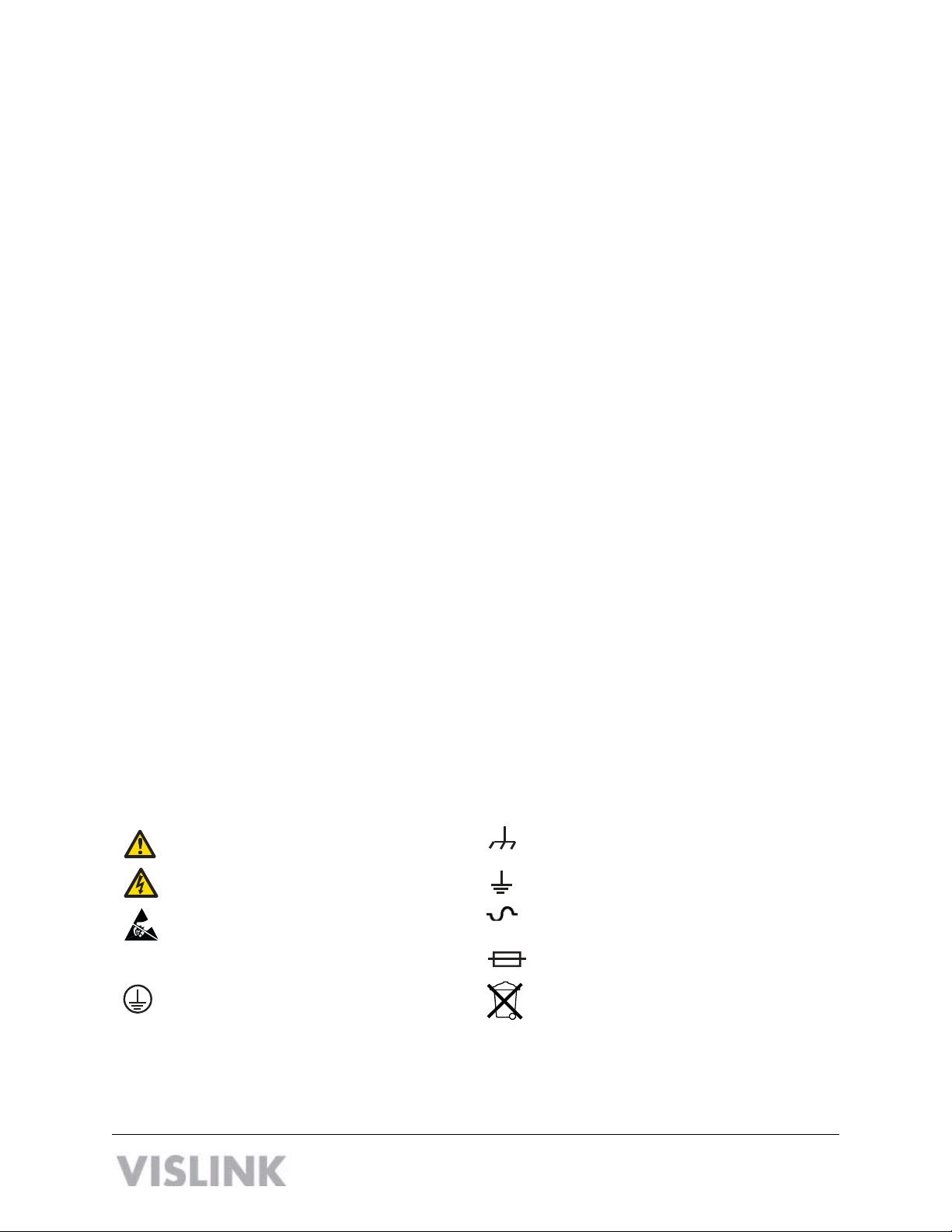
Symbols The following symbols may be on the equipment or in this manual:
WARNING: General Warning.
Risk of Danger.
Frame or Chassis Ground: Identifies the frame
or chassis terminal.
WARNING: Risk of Electric Shock. Earth Ground: Identifies the earth ground
terminal.
CAUTION: Electrostatic Discharge.
Possible Damage to Equipment. Fuse (either icon):
Identifies fuses or their location.
Protective Earth Ground: Identifies any
terminal intended for connection to an
external conductor for protection against elec-
tric shock in case of a fault, or the
terminal on a protective earth electrode.
Waste Electrical and Electronic Equipment
(WEEE): The product must not be disposed of
with other waste. You must dispose of the
waste equipment by handing it over to a desig-
nated collection point for recycling.
101 Billerica Avenue - Bldg. 6
North Billerica, MA 01862-1256 USA
TEL: 800.490.5700 or +1.978.671.5700 ii

Contents
1 About the DXL8000
1.1 DXL8000 System Applications - - - - - - - - - - - - - - - - - - - - - - - - - - - - - - - - - 1-3
1.2 DXL8000 Rear Panel Connectors- - - - - - - - - - - - - - - - - - - - - - - - - - - - - - - 1-8
1.3 About the Outdoor Unit - - - - - - - - - - - - - - - - - - - - - - - - - - - - - - - - - - - - - - 1-9
1.3.1 Integrated Coupler- - - - - - - - - - - - - - - - - - - - - - - - - - - - - - - - - - - - - - - 1-10
2 Installing the DXL8000
2.1 Unpacking the DXL8000 - - - - - - - - - - - - - - - - - - - - - - - - - - - - - - - - - - - - - 2-1
2.2 Preparing to Install the DXL8000 - - - - - - - - - - - - - - - - - - - - - - - - - - - - - - - 2-2
2.2.1 Operating in Safety - - - - - - - - - - - - - - - - - - - - - - - - - - - - - - - - - - - - - 2-1
2.2.2 Calculating MPE- - - - - - - - - - - - - - - - - - - - - - - - - - - - - - - - - - - - - - - - 2-2
2.2.3 Grounding the DXL8000 - - - - - - - - - - - - - - - - - - - - - - - - - - - - - - - - - 2-4
2.2.4 Ventilating the DXL8000 - - - - - - - - - - - - - - - - - - - - - - - - - - - - - - - - - 2-4
2.2.5 Protecting the DXL8000 from Moisture - - - - - - - - - - - - - - - - - - - - - - - 2-4
2.2.6 Routing Cables - - - - - - - - - - - - - - - - - - - - - - - - - - - - - - - - - - - - - - - - 2-5
2.2.7 Power Requirements - - - - - - - - - - - - - - - - - - - - - - - - - - - - - - - - - - - - 2-5
2.3 Installing the DXL8000 - - - - - - - - - - - - - - - - - - - - - - - - - - - - - - - - - - - - - - 2-6
3 Operating the DXL8000
3.1 Powering Up and Down - - - - - - - - - - - - - - - - - - - - - - - - - - - - - - - - - - - - - - 3-1
3.2 Setting Up the DXL8000 with a PC - - - - - - - - - - - - - - - - - - - - - - - - - - - - - - 3-1
3.3 Monitoring Status (Status Tab) - - - - - - - - - - - - - - - - - - - - - - - - - - - - - - - - - 3-2
3.3.1 Status–Help - - - - - - - - - - - - - - - - - - - - - - - - - - - - - - - - - - - - - - - - - - 3-2
3.3.2 Status–Identification - - - - - - - - - - - - - - - - - - - - - - - - - - - - - - - - - - - - 3-2
3.3.3 Status–Monitor Radio - - - - - - - - - - - - - - - - - - - - - - - - - - - - - - - - - - - 3-3
3.3.4 Status–Firmware Revisions - - - - - - - - - - - - - - - - - - - - - - - - - - - - - - - 3-3
3.3.5 Status–Monitor Mod - - - - - - - - - - - - - - - - - - - - - - - - - - - - - - - - - - - - 3-3
3.3.6 Status–Monitor Demod - - - - - - - - - - - - - - - - - - - - - - - - - - - - - - - - - - 3-4
3.3.7 Status–Monitor ODU - - - - - - - - - - - - - - - - - - - - - - - - - - - - - - - - - - - - 3-5
3.4 Setting System Parameters (Setup Tab) - - - - - - - - - - - - - - - - - - - - - - - - - - 3-6
3.4.1 Setup–Identification Screen - - - - - - - - - - - - - - - - - - - - - - - - - - - - - - - 3-6
3.4.2 Setup–Radio Screen - - - - - - - - - - - - - - - - - - - - - - - - - - - - - - - - - - - - 3-6
3.4.3 Setup–Modulator Screen - - - - - - - - - - - - - - - - - - - - - - - - - - - - - - - - - 3-7
3.4.4 Setup–Demodulator Screen - - - - - - - - - - - - - - - - - - - - - - - - - - - - - - - 3-8
3.4.5 Setup–ODU Screen- - - - - - - - - - - - - - - - - - - - - - - - - - - - - - - - - - - - - 3-9
3.4.6 Determining Overall System Capacity Versus Bandwidth - - - - - - - - - - 3-10
3.4.7 Determining Optimal Data Rate Versus Error Correction - - - - - - - - - - - 3-11
3.5 Creating User Accounts (Administration Tab) - - - - - - - - - - - - - - - - - - - - - - 3-11
3.6 Upgrading Software (Downloads Tab)- - - - - - - - - - - - - - - - - - - - - - - - - - - - 3-12
3.7 Managing Alarms - - - - - - - - - - - - - - - - - - - - - - - - - - - - - - - - - - - - - - - - - - 3-12
3.7.1 Interpreting the Front Panel LEDs - - - - - - - - - - - - - - - - - - - - - - - - - - - 3-12
3.7.2 Modifying Alarm Settings (Alarms Tab) - - - - - - - - - - - - - - - - - - - - - - - 3-13
3.7.3 Standard System Configuration - - - - - - - - - - - - - - - - - - - - - - - - - - - - 3-16
3.7.4 Protected System Configuration - - - - - - - - - - - - - - - - - - - - - - - - - - - - 3-17
DXL8000 User and Technical Manual Contents-1

Appendix A DXL8000 Specifications
A.1 AC and DC Power Connectors - - - - - - - - - - - - - - - - - - - - - - - - - - - - - - - A-1
A.2 MGMT Connectors - - - - - - - - - - - - - - - - - - - - - - - - - - - - - - - - - - - - - - - - A-1
A.3 IF IN and IF OUT Connectors - - - - - - - - - - - - - - - - - - - - - - - - - - - - - - - - A-1
A.4 IMC BUS Connectors - - - - - - - - - - - - - - - - - - - - - - - - - - - - - - - - - - - - - - A-1
A.5 T1/E1 CHAN1 and CHAN2 Connectors - - - - - - - - - - - - - - - - - - - - - - - - - A-2
A.6 WAYSIDE DATA Connectors- - - - - - - - - - - - - - - - - - - - - - - - - - - - - - - - - A-2
A.7 10/100 Connectors - - - - - - - - - - - - - - - - - - - - - - - - - - - - - - - - - - - - - - - - A-2
A.8 ASI/DS3/E3 and ASI/SMPTE310 Connectors - - - - - - - - - - - - - - - - - - - - - A-3
A.9 ODU DC on COAX - - - - - - - - - - - - - - - - - - - - - - - - - - - - - - - - - - - - - - - - A-3
A.10 SUMMARY ALARM Connectors - - - - - - - - - - - - - - - - - - - - - - - - - - - - - - A-3
A.11 General Specifications - - - - - - - - - - - - - - - - - - - - - - - - - - -- - -- - - - - - - A-4
A.12 User Definable Signal Interface Options - - - - - - - - - - - - - - - - - -- - - - - - - A-4
A.13 Standards Compliance - - - - - - - - - - - - - - - - - - - - - - - - - - - - - -- - - - - - A-4
A.14 Physical - ODU - -- - - - - - - - - - - - - - - - - - - - - - - - - - - - - - - - -- - - - - - - A-4
A.15 Physical - IDU - - - - -- - - - - - - - - - - - - - - - - - - - - - - - - - - - - - - - - - - - - - A-4
Index
Safety Instructions
• Always use the correct power source during operation to avoid damaging the product.
• Rough handling of the product may cause physical damage or malfunction.
• It is not recommended to use the DXL8000 in harsh weather conditions or very low or high
temperatures.
• To ensure that the warranty remains valid, please do not disassemble the unit.
Contents-2 DXL8000 User and Technical Manual

1 About the DXL8000
The DXL8000 Short-Haul Microwave System (DXL8000) is a cost-effective, high performance,
highly reliable, flexible, and compact microwave link for short haul applications. The DXL8000
6 to 23 GHz Short Haul Radio is also a split-mount, digital, duplex microwave radio designed
for Studio to Transmitter, Transmitter to Studio and “last mile” point to point applications. The
DXL8000 delivers aggregate data rates up to 170 Mbps at 64QAM modulation (license
dependent). The DXL8000 consists of the Indoor Unit (IDU) and an Outdoor Unit (ODU) as
shown below:
The DXL8000 provides high-quality digital transmission under a Single Carrier QPSK/QAM
Modulation (SCM) scheme and is available in simplex or duplex and Hot Standby (1+1), using
the Hot Standby protection switch. The DXL8000 digital microwave transceiver can support
video and data transmissions.
• The DXL8000 is a digital mode transceiver that accepts multiple transport data streams
or an external 70 MHz digitally modulated IF signal. The input data streams are
multiplexed and are modulated onto the IF signal using Single Carrier QPSK/QAM
Modulation. Then the modulated IF signal (or external IF signal) is up-converted to the
final radio frequency (RF) required and is transmitted through the antenna.
• The DXL8000 transceiver also receives RF signals from the antenna and down-converts
the RF signals to a 70 MHz IF. The original data streams are demodulated using Single
Carrier QPSK/QAM Demodulation. IF output is also available for connection to an
external demodulator or test equipment.
The DXL8000 supports from 1 – 4 independent, user selectable transport streams, and includes
Web browser management Interface to optimize transmission parameters for maximum spectral
efficiency. Transport stream options include ASI, SMPTE 310M, in support of ATSC, DVB-T,
ISDB-T BTS and DS3 / E3, 100BaseTX Ethernet, RS232, RS485 and T1/ E1. The advanced
digital modulator includes Viterbi error correction for ultra-robust performance under adverse
path conditions, while the adaptive equalizer at the receiver automatically compensates for
multipath errors.
DXL8000 User and Technical Manual About the DXL8000 1-1

The DXL8000 is designed to install, setup, and manage easily. The split mount design enables
the use of economical coaxial interconnects between the Indoor Unit and the rooftop or tower
mounted Outdoor Unit. The radio’s advanced control processor with embedded web server
provides a rich set of control and configuration options both locally, and remotely, over a secure
IP connection.
All operating parameters are monitored by the control processor which immediately reports
alarm conditions via the graphical interface and relay contacts. Alarms may be customized to
suit user preferences, and a wayside serial port is included for service channel support.
The DXL8000 Short Haul Radio delivers industry leading throughput performance, an extensive
range of interface options and advanced configuration and control to meet broadcasters’
requirements and future growth plans.
Features
■Send up to 3 ASI Signals Simultaneously
■Part 74 FCC Compliant
■Easy to Use Web Browser Monitor & Control
■Fully Enabled Out of the Box (no additional licenses to purchase)
■Duplex Mode Enables High-Speed Ethernet
■High Performance
•Up to 170 Mbps throughput
•Integrated Multiplexer & Modulator
•Duplex and Simplex configurations
■Multiple Transport Streams
•ATSC, DVB-T, ISDB-T BTS
•SMPTE 310M, ASI
•10/100 Ethernet
•Telco DS3/E3, RS232, RS485 and T1/E1
■Advanced Management functionality
•Browser based local and remote configuration/ monitoring
•Firmware upgrades in the field
•Embedded Wayside data channel
■Designed for Reliability
•Transmitter provides ultra-robust performance under adverse path conditions
•Receiver automatically compensates for multi-path errors
•Versatile 1 RU split mount design configurations
■IF Only option for use with external 70 MHz modems
■ANSI and ETSI Versions
1-2 About the DXL8000 1-2DXL8000 User and Technical Manual

1.1 DXL8000 System Applications
The DXL8000 may be deployed for the following applications:
• “Last Mile” Point-to-Point Microwave
• Studio to Transmitter Link
• Short to Medium Range Transmission
• Operational Fixed-Link Service (OFS)
• Studio-to-Transmitter Links (STL)
• Transmitter-to-Studio Links (TSL)
• Intercity Relay (ICR)
• Common Carrier (CC)
• Multi-channel broadcast
• Community Antenna Relay Service (CARS)
• Standard Definition Television (SDTV),
• High Definition Television (HDTV)
• TV Translator Relay (TT)
• Single Frequency Network (SFN)
• Low Power TV Relay (LPTV STL)
• Mounting Options—The IDU mounts in a standard 19-inch (48.3 cm) rack with the
standard height of 1RU. The ODU unit can be mounted on a mast or in a bracket for
indoor mounting and use a coupler as described in section 1.3.1.
DXL8000 User and Technical Manual About the DXL8000 1-3
• The ODU transmits and receives the signals. The ODU has snap mount clips for easy
installation with the following antennas:
Band Antenna Diameter Gain FCC ETSI
5.725–7.125 GHz* HP6-6 6 (1.8M) 39.3 Cat A 302217 R1 C2
7.125-8.25 GHz HP6-7.7 6 (1.8 M) 40.3 N/A 302217 R1 C3
10.15–11.7 GHz
HP2-1011 2 (1.8M) 43.8 Cat A 302217 R1 C2
HP3-11 3 (0.9 M) 38.5 Cat A 302217 R1 C3
HP4-1011 4 (1.2 M) 40.4 Cat A 302217 R1 C2
HP6-1011 6 (1.8 M) 43.8 Cat A 302217 R1 C2
12.7-13.25 GHz
HP2-13 2 (0.6 M) 35.9 N/A 302217 R1 C2
HP3-13 3 (0.9 M) 38.7 N/A 302217 R1 C2
HP4-13 4 (1.2 M) 41.9 Cat B 302217 R1 C2
HP6-13 6 (1.8 M) 44.4 Cat A 302217 R1 C3
14.25-15.35 GHz
HP2-15 2 (0.6 M) 37.0 N/A 302217 R2 C3
HP3-15 3 (0.9 M) 40.0 N/A 302217 R2 C2
HP4-15 4 (1.2 M) 42.5 N/A 302217 R2 C3
HP6-15 6 (1.8 M) 45.9 N/A 302217 R2 C2
17.7–19.7 GHz
HP2-18 2 (0.6 M) 38.6 Cat A 302217 R2 C3
HP3-18 3 (0.9 M) 43.5 Cat A 302217 R2 C3
HP4-18 4 (1.2 M) 44.5 Cat A 302217 R2 C3
HP6-18 6 (1.8 M) 48.0 Cat A 302217 R2 C2
21.2–23.6 GHz
HP2-23 2 (0.6 M) 40.2 Cat A 302217 R3 C3
HP3-23 3 (0.9 M) 43.7 Cat A 302217 R3 C3
HP4-23 4 (1.2 M) 46.2 Cat A 302217 R3 C3
HP6-23 6 (1.8 M) 49.2 Cat A 302217 R3 C2
* The 5.9–6.4 and 6.4–7.1 GHz band models are fixed-rectan ular feeds and cannot be rotated.
1-4 About the DXL8000 DXL8000 User and Technical Manual

• RF Performance
RF Band Frequency
Tolerance %
Channel
B/W MHz
Duplex
T/R
Spacing
MHz
Typ RF
O/P QPSK
dBm
Typ RF O/P
16QAM
dBm
Typ RF O/P
128QAM
dBm
Rx
Threshold
16QAM
dBm
5.9–6.4 0.001 30 252.04 25 24 24 -78
6.4–7.010.001 7, 14, 28, 40 340 25 24 24 -78
7.1-7.9 0.001 7, 14, 28, 40 245 30 28 24 -78
10.7–11.7 0.001 30, 40 490/500 28 26 21 -77
12.7-13.3 0.001 3.5, 7, 14, 28, 40 266 26 23 18 -76
14.5-15.9 0.001 3.5, 7, 14, 28, 40 728 26 23 18 -76
17.7–18.4 0.001 10, 20, 302, 40 1560 26 22 18 -77
19.2–19.7 0.001 10, 20, 302, 40 1560 26 22 17 -77
21.2–22.4 0.001 10, 20, 30, 40 1200 25 22 17 -76
1. ETSI—Not available in the USA; export applications only.
2. Part 101 only; 30 MHz channels not available in Part 74 FCC at 18 GHz
• Polarization orientation—You can orient the path polarization mark on the ODU for
horizontal or vertical polarization on the antenna. (See Section 1.3, About the Outdoor
Unit.)
• Central processors control system functions and operations. You can control the
DXL8000 with a PC using an embedded control firmware package and a graphical user
interface (GUI). See Section 3.2, Setting Up the DXL8000 with a PC for more
information about using the GUI.
• Frequency ranges as shown in the following table:
Band Group &
Tx Split
TX Range
[MHz]
RX Range
[MHz] Tx/Rx Spacing FCC/ETSI
5.9–6.4 GHz
1 Low Tx 5929-6025 6175-6275
252.04 MHz FCC Part 101
1 High Tx 6175-6275 5929-6025
2 Low Tx 6000-6100 6250-6350
2 High Tx 6250-6350 6000-6100
3 Low Tx 6075-6175 6325-6425
3 High Tx 6325-6425 6075-6175
DXL8000 User and Technical Manual About the DXL8000 1-5

• Frequency ranges continued:
Band Group &
Tx Split
TX Range
[MHz]
RX Range
[MHz] Tx/Rx Spacing FCC/ETSI
6.4–7.1 GHz 1 Low Tx 6430-6450 6770-6880 340 MHz ETSI only; not for
US/FCC
applications
FCC Part 74 &
101
1 High Tx 6770-6880 6430-6450
2 Low Tx 6520-6630 6860-6970
2 High Tx 6860-6970 6520-6630
3 Low Tx 6600-6710 6940-7050
3 High Tx 6940-7050 6600-6710
4 Low Tx 6670-6780 7010-7120
4 High Tx 7010-7120 6670-6780
7.4 – 7.9 GHz 1 Low Tx 7400-7484 7645-7729 245 MHz FCC Part 101
1 High Tx 7645-7729 7890-7974
2 Low Tx 7484-7568 7729-7813
2 High Tx 7729-7813 7974-8058
3 Low Tx 7568-7652 7813-7897
3 High Tx 7813-7897 8058-8142
10.6-11.7 GHz 1 Low Tx 10675-10855 11165-11375 490 MHz FCC Part 74 &
101
1 High Tx 11165-11345 11655-11835
2 Low Tx 10795-10975 11285-11465
2 High Tx 10915-11095 11405-11585
3 Low Tx 11405-11585 11895-12075
3 High Tx 11035-11215 11525-11705
4 High Tx 11525-11705 12015-12195
4 Low Tx 10700-10890 11190-11380
5 High Tx 11200-11390 11700-11355 490/500 MHz
5 Low Tx 10855-11045 11355-11545
6 High Tx 11355-11545 11855-12045
6 High Tx 11010-11200 11510-11700
7 Low Tx 11510-11700 12010-12200
1-6 About the DXL8000 DXL8000 User and Technical Manual

• Frequency ranges continued:
Band Group &
Tx Split
TX Range
[MHz]
RX Range
[MHz] Tx/Rx Spacing FCC/ETSI
12.7-13.3 GHz 1 Low Tx 12751-12814 13017-13080 266 MHz FCC Part 74 &
101
1 High Tx 13017-13080 13283-13346
2 Low Tx 12807-12870 13073-13136
2 High Tx 13073-13136 13339-13402
3 Low Tx 12863-12926 13129-13192
3 High Tx 13129-13192 13395-13458
4 High Tx 12919-12982 13185-13248
4 Low Tx 13185-13248 13451-13514
14.5-15.9 GHz 1 Low Tx 14500-14615 15228-15343 728 MHz FCC Part 74 &
101
1 High Tx 15228-15343 15956-16071
2 Low Tx 14500-14625 15228-15353
2 High Tx 15228-15353 15956-16081
17.7–19.7 GHz 1 Low Tx 17700-18140 19260-19,700 1560 MHz FCC Part 74 &
101
1 High Tx 19260-19700 17700-18,140
21.2–23.6 GHz 1 Low Tx 21200-21600 22400-22,800 1200 MHz FCC Part 101
1 High Tx 22400-22800 21200-21,600
2 Low Tx 21600-22000 22800-23,200
2 High Tx 22800-23200 21600-22,000
3 Low Tx 22000-22400 23200-23,600
3 High Tx 23200-23600 22000-22,400
DXL8000 User and Technical Manual
About the DXL8000 1-7
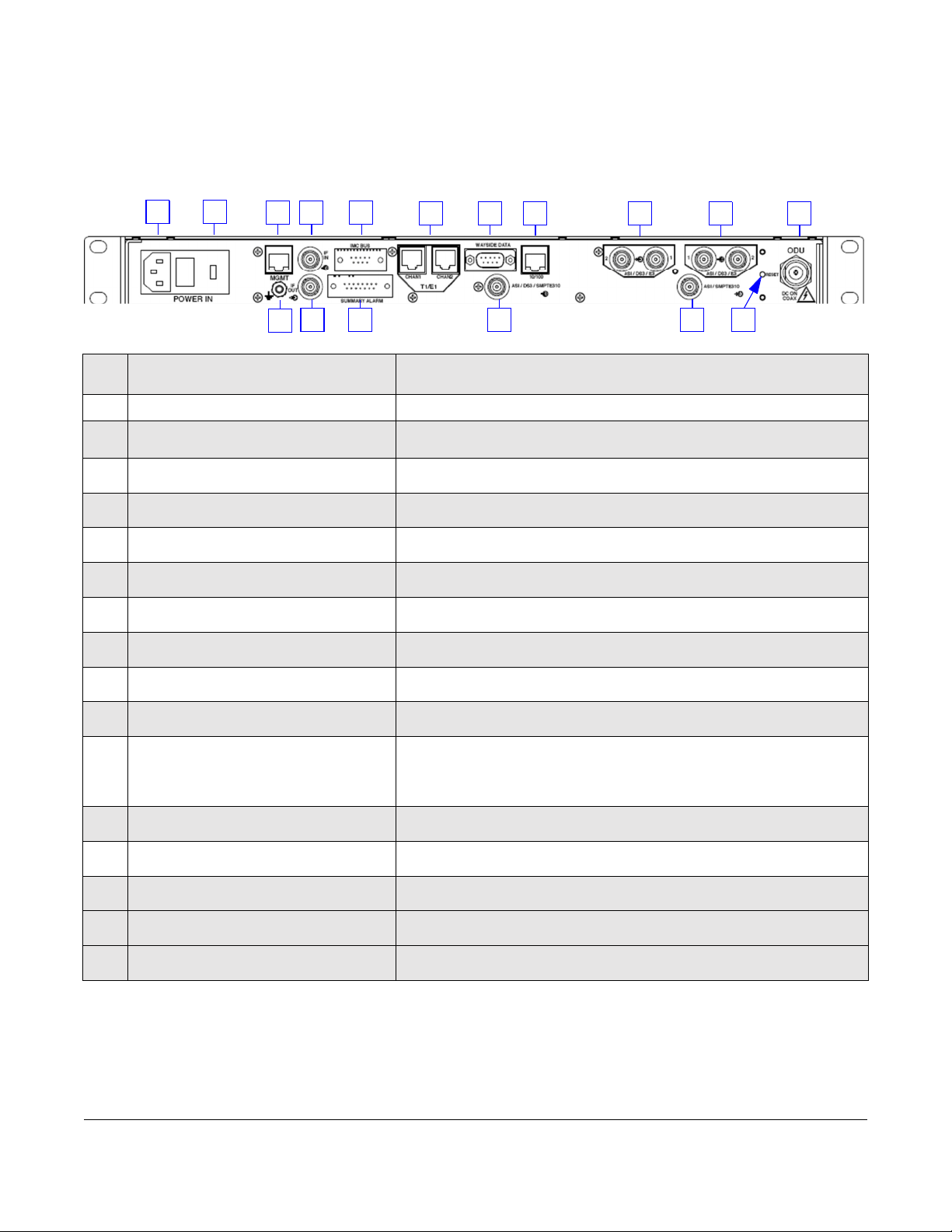
1.2 DXL8000 Rear Panel Connectors
The following figure shows the rear panel of the DXL8000 followed by the description of each
connector. For information about connector specifications, see Appendix A, DXL8000
Specifications.
1 2 3 4 5 6 7 8 9 10 11
17 16 15 14 13 12
1POWER IN connector Connects to the removable external power cables. The 115-120 VAC
connection is shown. The DC input receptacle is a 2 pin male connection.
2AC power fuse Provides input power overload protection.
3MGMT
RJ-45 connector
Connects to a 10 Base T Ethernet cable to control the
DXL8000 from a PC.
4IF IN
75 Ohm BNC female connector
Provides the 70 MHz (–10 dBm) IF input.
5IMC BUS
9-pin male connector
Reserved. (Not used.)
6T1/E1 CHAN1 and CHAN2
RJ-45 connectors
Provides T1/E1 I/O connections for channels 1 and 2.
7WAYSIDE DATA
9-pin male connector
Provides RS-232 or RS-485 input for wayside data
transmission via the SCM modem.
810/100
RJ-45 connector
Provides 10/100 Base T Ethernet connection.
9ASI/DS3/E3 1 and 2 Output
75 Ohm BNC female connectors
Provides ASI or DS3/E3 outputs.
10 ASI/DS3/E3 1 and 2 Input
75 Ohm BNC female connectors
Provides ASI or DS3/E3 inputs.
11 ODU (DC ON COAX) Type N
female connector
Provides IF signals with the connection between the IDU, ODU, and
DC power on the coaxial cable.
12 RESET Switch When pressed and held for about 5 seconds, the 4-digit dBm display
flashes and resets the IP address, subnet mask, and default gateway
addresses to the factory default addresses. It does not affect other
password or configuration settings.
13 ASI/SMPTE310 3 Output
75 Ohm BNC female connector
Provides ASI or SMPTE310 outputs.
14 ASI/SMPTE310 3 Input
75 Ohm BNC female connector
Provides ASI or SMPTE310 inputs.
15 SUMMARY ALARM
15-pin female connector
Provides summary alarm contacts for major and minor events. See
Section A.10, SUMMARY ALARM Connectors for more information.
16 IF OUT
75 Ohm BNC female connector
Provides the 70 MHz (–10 dBm) IF output.
17 Ground Provides grounding for the DXL8000.
1-8 About the DXL8000 DXL8000 User and Technical Manual

1.3 About the Outdoor Unit
The following figure shows the front and rear of the DXL8000 Outdoor unit (ODU).
• The front of the ODU has a path polarization mark (arrow) to orient the antenna to
horizontal or vertical polarity.
• The ODU has a fixed-rectangular waveguide at 6 and 7 GHz and cannot be rotated.
• The ODU has a circular waveguide at 11 through 23 GHz.
• The ODU has snap clips for antenna mount.
• You can have a separation of up to 850 ft. (260 M) with 1/2” foam cable. Type N
connectors are required at both ends of the cable. Permissible IF cable loss to the
ODU is about 22 dB maximum. Recommended cables are Times LMR-400 or Andrew
LDF4-50A.
• The center mounting shown on the rear image includes a waveguide hookup for a
Remote Mount Kit (RMK), which is described on the next page.
The following figure shows the ODU, its connections and an ODU integrated with an antenna.
Type N IF interface
IF/DC in/out from IDU
Waveguide hookup
BNC connector
RSL/AGC test point is a
Receive Signal Level Indicator
for antenna alignment; DC
voltage output 0 - 4.5 VDC
DXL8000 User and Technical Manual
About the DXL8000 1-9
1.3.1 Antenna Alignment
The antenna can be aligned while during operation using the BNC connector shown above. This
Receive Signal Level Indicator (VBNC) has the following specifications:
4.5 (typical) @ -20 dBm RSL, 0.1 (typical) @ -90 dBm RSL, monotonic
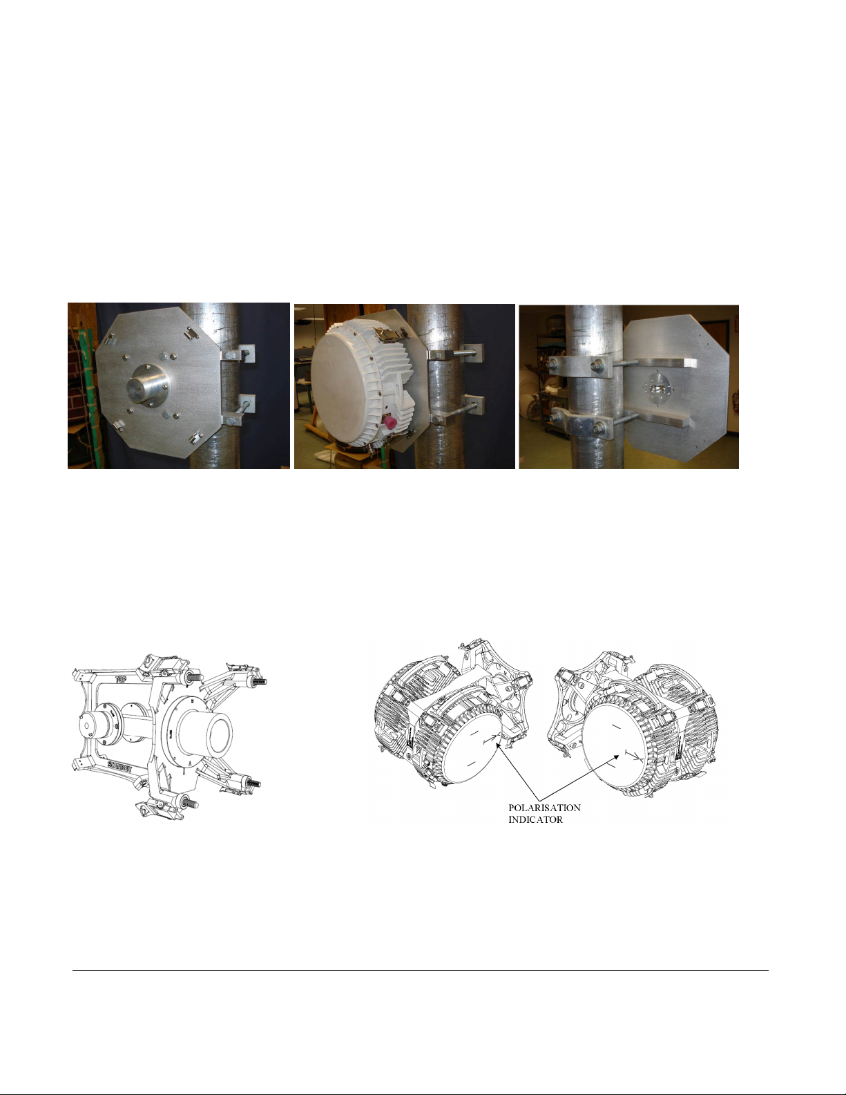
1.3.2 Remote Mount Kit Antenna Configuration
The Remote Mount Kit (RMK) allows you to use existing antennas. The RMK is pole mounted
behind existing antennas. A short section of Flexible Waveguide runs from the RF Head to the
Antenna Feed using standard waveguide flanges. The following images show the RMK ODU
mounting plate, the plate with the ODU attached and the waveguide hookup.
1.3.3 Integrated Coupler
For protected DXL8000 applications (i.e. when the Hot Standby switch is part of the system), an
integrated coupler may be used to pair ODUs on a single mounting. An example of this dual
mounting is shown below.
Integrated Coupler Dual Head ODUs
1-10 About the DXL8000 DXL8000 User and Technical Manual

2 Installing the DXL8000
This chapter describes how to unpack and install your DXL8000 Short-Haul Microwave System.
CAUTION If you modify the product without authorization from MRC, you
will void the warranty.
2.1 Unpacking the DXL8000
Carefully unpack your new equipment to avoid accidental damage.
NOTE:DO NOT discard the container or packing material until you have inspected the
equipment and are sure there is no shipping damage. The container and
packing must be available in case you need to file a damage claim with the
shipping carrier.
• Inspect the equipment for damage and that it is clean and dry.
• Inspect the cables, connectors, switches, and displays to ensure that they are not
broken, damaged or loose.
If you discover damage after unpacking the system, report the damage as follows:
• Immediately file a claim with the shipping carrier.
• Forward a copy of the damage report to Vislink Customer Service.
• Contact Customer Service to determine the disposition of the equipment. See
Section 1.3, About the Outdoor Unit.
2.2 Preparing to Install the DXL8000
The following sections describe the things you should consider before installing the DXL8000.
2.2.1 Operating in Safety
CAUTION Ensure that the power being supplied matches the power
required by the equipment. You can find power ratings for
equipment on a rating plate, usually on the rear panel.
Ensure that the electrical supply is protected by over-current
protection devices as required by the applicable electrical
codes. If necessary, consult a licensed electrician.
DXL8000 User and Technical Manual Installing the DXL8000 2-1

An AC power cable comes with each DXL8000 IDU. The DXL8000 IDU supplies -48V DC
power to the Outdoor Unit (ODU) from the rear panel ODU DC ON COAX Type N connector.
WARNING - RF Power Hazard
WARNING The unit has high levels of RF power. Exposure to RF or microwave
power can cause burns and may be harmful to health.
• Remove power from the unit before disconnecting any RF cables and before inspecting
damaged cables and/or antennas.
• Avoid standing in front of high gain antennas (such as a dish antenna) and never look
into the open end of a waveguide or cable where RF power may be present.
The following guidelines for safe operation were derived from OET bulletin 65, August 1997, as
recommended by the Federal Communications Commission (FCC).
The DXL8000 was designed to provide services to licensees under 74 CFR, subpart F,
television broadcast auxiliary stations, and under 101 CFR, subpart H, private operational fixed
point-to-point microwave service. This unit, operated without an antenna, will not create RF
energy exceeding 1.0 mW/cm2, the FCC limit for exposure. Once connected to an antenna, the
potential for harmful exposure will be greatly enhanced.
In this situation, a certain distance from the radiator is to be maintained. Calculations need to be
Permissible Exposure (MPE) limit.
Calculations provided are for common antennas often utilized in point-to-point applications. The
following formula used is that suggested by OET 65.
2.2.2 Calculating MPE
EIRP =P * [10(G / 10)]=(AntiLog of G/10)*P
P= RF power delivered to the antenna in mW
G= Power gain of the antenna in the direction of interest relative to an isotropic radiator
R= distance to the center of radiation of the antenna in centimeters
S= MPE in mW/cm² (milliwatts per square centimeters)
Conversions
dBi to numeric gain = AntiLog (dBi/10) Feet to centimeters = Feet *30.48
Centimeters to Feet = cm *.0328
4 π= 12.57
User Input
RF power delivered to the antenna = Watts
Antenna gain (referenced to isotropic antenna) = dBi
Distance from the center of radiation = Feet
2-2 Installing the DXL8000 DXL8000 User and Technical Manual

Antenna
Gain
(dBi)
Minimum Safe
Distance from
Antenna (cm)
Minimum Safe
Distance from
Antenna (inch)
0
9
3.54
29
252
99.19
36
563
221.60
40
893
351.48
43
1261
496.33
Power
Density
(mW/cm^2)
Calculation steps:
1. [P] RF power input. Watts to milliwatts = Watts *1000
2. [G] Antenna gain dBi. Numeric gain = AntiLog (dBi/10)
3. [EIRP] Multiply P *G
4. [R] Centimeters to feet = Centimeters *.0328
5. Square R
6. Multiply R² *4π
7. [S] Divide (R² *4π) into EIRP
S= Power Density in milliwatts per square centimeters.
NOTE:At frequencies above 1500 MHz, S must not be greater than 1.
Reference
FCC OET Bulletin 65, August 1997 - Evaluating Compliance with FCC Guidelines for
Human Exposure to Radio Frequency Electromagnetic Fields
The following graphs and associated tables show the permissible exposure distance for various
antennas. Graphs and data will vary, based on the actual transmitter, output power, frequency,
and antenna utilized. One plot provides the permissible output of the transmitter for low-power
digital modulation, and the other plot for high-power digital modulation.
This information is provided, in accordance with the requirements set forth by the FCC, as a
guide for you assuming that users of this equipment are licensed and qualified to operate the
equipment per the guidelines and recommendations contained within the product user guides
and in accordance with any FCC rules that may apply.
Low Power
MaximumPermissible
Exposure
All Bands, Standard Power1Watt (+30dBm)
80
70
60
50
40
30
20
10
0
0 2 4 6 8
101214161820
222426283032343638404244
4648
5052545658
Distance
inFeet
0dBi
29dBi
36dBi
40dBi
43dBi
DXL8000 User and Technical Manual Installing the DXL8000 2-3

Antenna
Gain
(dBi)
Minimum Safe
Distance from
Antenna (cm)
Minimum Safe
Distance from
Antenna (inch)
0
13
5.12
29
356
140.12
36
797
313.70
40
1262
496.72
43
1783
701.79
Power Density (mW/cm^2)
High Power
MaximumPermissibleExposure
All Bands, High Power
2Watts(+33dBm)
80
70
60
50
40
30
20
10
0
0 2 4 6
8
10121416182022242628303234363840424446485052545658
DistanceinFeet
0dBi
29dBi
36dBi
40dBi
43dBi
2.2.3 Grounding the DXL8000
CAUTION Be sure the equipment grounding follows applicable electrical codes.
Never modify a grounded power plug to connect to an ungrounded
receptacle.
For safe operation, all equipment must be properly grounded.
• Make the ground wire as short and straight as possible.
• Connect the DXL8000 IDU ground lug to the common ground on the installation.
• Connect the common ground to site ground.
2.2.4 Ventilating the DXL8000
CAUTION Temperatures inside a closed mounting area can be significantly higher
than the ambient temperature. Always allow adequate ventilation.
If possible, install components in a climate-controlled area. Allow adequate airflow around the
equipment. Exhaust air from the rack should be circulated and not trapped in a closed space.
2.2.5 Protecting the DXL8000 from Moisture
Locate the equipment in an area protected from dripping water or excessive humidity.
WARNING If water penetrates the chassis, it could cause equipment damage and
create a safety hazard.
2-4 Installing the DXL8000 DXL8000 User and Technical Manual

2.2.6 Routing Cables
Wiring is affected by temperature, humidity, and vibration extremes. You should do the following
installation.
CAUTION Power supply cords and cables must be protected. Do not run cords
where they can be stepped on. Protect cables against pinching and
chafing. Pay special attention to locations where the cables enter or exit
an enclosure or make a sharp bend.
• Secure all cables at close intervals along their entire lengths.
• Protect cabling with added sheathing or padding anywhere cabling passes through a
hole or lies against an obstruction.
• Provide flex relief at any location where the cable must change direction sharply, to
maintain a smooth bend and prevent kinking.
• Provide strain relief at each connector to absorb any pulling forces on the cable and
prevent damage to the connector.
• If long lengths of cable are required, you may need a UHF amplifier or gain block.
Contact Vislink for specific cable types and lengths to use in your application. For specific cable
types and lengths to use in your DXL8000, contact Customer Support; see Section 1.3, About
the Outdoor Unit.
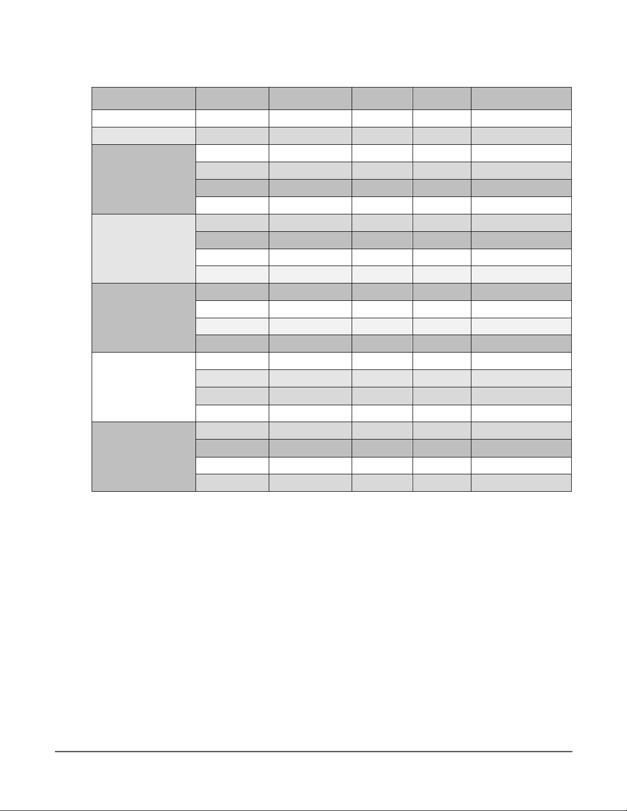
2.2.7 Power Requirements
The DXL8000 operates on 115/230 VAC, 50/60 Hz and - 48 VDC. Fuse ratings for the AC and
DC power sources are as follows:
Operating Voltage Fuse Rating Power Consumption
230 VAC, 50/60 Hz 1.0A, 250V AGC, Fast Blow
120W maximum
115 VAC, 50/60 Hz 2.0A, 250V AGC, Fast Blow
-48VDC,1.2 A, 3 A, Slow Blow 57.6 W
CAUTION Ensure that the power being supplied matches the power required by
the equipment. You can find power ratings for equipment on a rating
plate, usually on the rear panel. Ensure that the electrical supply is
protected by over-current protection devices as required by the
applicable electrical codes. If necessary, consult a licensed electrician.
DC Power Operations
When you are operating an unprotected Transmitter, Receiver and ODU system your DC input
should incorporate a properly grounded, 1.2 A, 57.6 W regulated power supply. It is crucial that
overload, over voltage and over temperature protection that shuts down the power supply
should be built in. The incidental increase in amperage should shut down the power supply and
then restore power upon recovery to avoid equipment damage.
For a protected system, the 48 VDC is supplied by the DXL Hot Standby switch. For more
information, refer to the DXL8000 Hot Standby Protection Switch User Guide.
DXL8000 User and Technical Manual Installing the DXL8000 2-5

2.3 Installing the DXL8000
The DXL8000 mounts into the mounting rails of a standard equipment rack. The unit occupies 1
rack unit (1RU) of height as shown in the following figure.
Mounting
Screws
(typ.)
WARNING:Follow instructions carefully. Do not place the equipment on an unstable
support, such as a cart, stand, or table. The equipment could fall and
cause equipment damage or cause injury.
• Position the rack to allow easy access to the front and rear of the equipment.
• Be sure to allow room behind the equipment rack for the cables required. Do not press
the cables against the rear of the equipment when closing doors because it stresses the
cables and may shorten their life.
• Do not overload the rack or load it unevenly. Secure the rack to a solid surface. Make
certain that the rack and mounting rails are strong and rigid enough to support all the
equipment in the rack.
To mount the DXL8000, do the following. (Mounting the DXL8000 into an equipment rack is
easier if one person holds the unit while another person installs the mounting screws.)
1. Lift the DXL8000 IDU into place, lining up the mounting holes with the holes in the rack
mounting rails as shown in the figure.
2. Install the two bottom screws first and tighten securely with lock washers to prevent
loosening.
3. Install the top two screws and tighten securely with lock washers to prevent loosening.
2-6 Installing the DXL8000 DXL8000 User and Technical Manual
Table of contents


