manuals.online logo
Brands
  1. Home
  2. •
  3. Brands
  4. •
  5. Philco
  6. •
  7. Radio
  8. •
  9. Philco 121 User manual

Philco 121 User manual

PHILCO
REG.U.S.PAT,orr
Service Bulletin No.·.2.2.2
Model 116B (Code 121)
GENERAL SPECIFICATIONS
Type Circuit: Superheterodyne, with push-pull pentodes
connected as triodes in output; output 10 watts; built in
connections for Philco All-wave aerial; aerial selector built
into and operated by wave-band switch.
Power Supply: Alternating Current. Voltage and fre-
quency as specified on chassis nameplate.
Tubes Used: Eleven (11) Total: 1 type 78 R.F., 1 type 77
1st detector, 1 type 76 oscillator, 2 type 78 I.F., 1 type 37
2nd detector, 1 type 77 1st audio, 1 type 42 driver, 2 type
42 output, 1 type 80 rectifier.
Wave Bands: Five-(1) Shortwave, daytime; (2) Short-
wave, night-time; (3) Police and amateur; (4) Standard
Broadcast; (5) Longwave (weather forecasts).
Frequency Ranges: Band (1)-9.7-22.5 Megacycles; Band
(2)-4.1-10.0 Megacycles; Band (3)-1.5-4.1 Megacycles;
Band (4)-540 to 1500 K.C.; Band (5)-150-390 K.C.
Program Control: 5 positions: (1) Mellow, (2) Brilliant,
(3) Speech, _(4)Normal, (5) noise reducing. Last two positions
recommended for foreign short wave stations.
Tuning Meter: Shadow type tuning meter, mounted
directly above scale.
Waveband Indicator: Glowing arrow on tuning scale shifts
to proper scale when waveband switch is turned.
Automatic Volume Control: Fully effective on all
stations.
Bass Compensation: Automatic: Effective when needed.
Tube
Point
---------
p
---SG
----K
----
Tube Socket Voltages
Measured to Ground-Line Voltage 115
78 77 76 78 78 37 77 42
R.F. 1st Osc. 1st 2d 2d 1st Dri-
Det. I.F. I.F. Det. A.F. ver
---- -- --- -- -- --- -- --
187 202 75 193 199 () 67 192
-- --- -- -- -- -- -- --
74 74 .. ' 74 74 '' 52 192
-- -- -- -- -- -- -- --
I. 8 5.4 5.0 I. 8 5. 1 '' '. ' ..
80 Rect. Cathode-290V.
42
Out-
put
--
279
--
279
---
...
Above voltages were obtained by using a PHILCO type 025 Circuit
Tester (or 048A All-purpose Tester), using test prods applied to underside
of chassis. Volume control at minimum; dial at 55; waveband switch
standard broadcast (band 4). Use Fig, I for test points. H-13 Speaker used.
Tuning Drive: Dual planetary, ball bearing. 80 to 1ratio
for slow-speed tuning, 10 to 1 for main drive.
Intermediate Frequency: 460 K.C.
Power Consumption: 100 watts.
Speaker: Type H-13.
78
JST.,J,F,
Fooi=l80
~RECTIFIER
42
.ll.BJfil
~
~
Fig. 1. Tube Sockets as viewed from bottom
Power Transformer Data
Term- A.C. Current Circuit Color
inals Volts
--~- 1-2 120 ...... Primary White
3~5 720 123 M.A. :secondary Yellow
6-7 5.0 2.0 A. Fil. 'Rect. Blue
8-9 6.3 5.0 A. Filaments Black
4 ''. ...... Center Tap of Yellow, Green
3-5 Tracer
Adjusting Compensating Condensers
Fig. 2. Locations of Compensating Condensers
Adjustment of compensating condensers in Model 116
. requires an accurate signal generator covering long-wave,
standard wave, police, and short-wave frequencies. The
PHILCO 'Model 088 All-Wave Signal Generator, having a
continuous range of from 100 to 20000 K.C. will be ideal for
this purpose.
An output meter is also needed. PHILCO Model 025 Circuit
Tester includes a high-grade output meter.
Philco No. 3164 fibre wrench and No. 27-7059 fibre handled
screwdriver complete the equipment needed for making these
· adjustments. The locations of the various compensating
condensers is shown in Fig. 2. Connect the output meter to
the plate contacts of the output tubes (using the adapters
provided with the "025") and set it at the 0-30 volt range.
I.F.-Set the Signal Generator at 460 K.C., and attach its
antenna lead to the grid cap of the 77 1st detector tube
(having removed the grid clip from the tube). Connect the
ground terminal of the Signal Generator to the ground term-
inal of the set. Turn on the set, turn the waveband switch to
philcoradio.com
,.,:191~1
~~}L
~
"'-
~i
2.so.oooc,.
rt»
~
F
~(II'
NUMBERSINDICATERELATIVE POSITIONS Of SWITCH-
SECTIONS
FROM rRoNr or cHAss1s {23r;;I
fl -----,
f1r:s._____________ :
(]?_ • )
so-ff, d IEl -
®l F
~
it
0
~-
~~
llf]-®
~~
ill-®
~1'""1-®
0
~----_JL
...., ',,,,,
27) ...................
~
-o, 0 I (103:
'b
:)r·it
2 3 4 '=
:I-@
'-8
1.~
p.,..,
0'o, ALL SWITCH-SECTIONS
1o o-+os SHOWN
' J ---
' 11
J~.F.:4 6 0 KC. @--+~- IN POSITION N° 5
Fig. 3. Schematic Diagram of Model 116-121
i
....
~
~
~
.,,
n::c:
~-
~r-
c: n
=o
~
f"t
....
=
z
~
....
....
....
philcoradio.com
No. 222 PH I LCO
Service Bulletin Page 3
Replacement Parts~Model 116~121
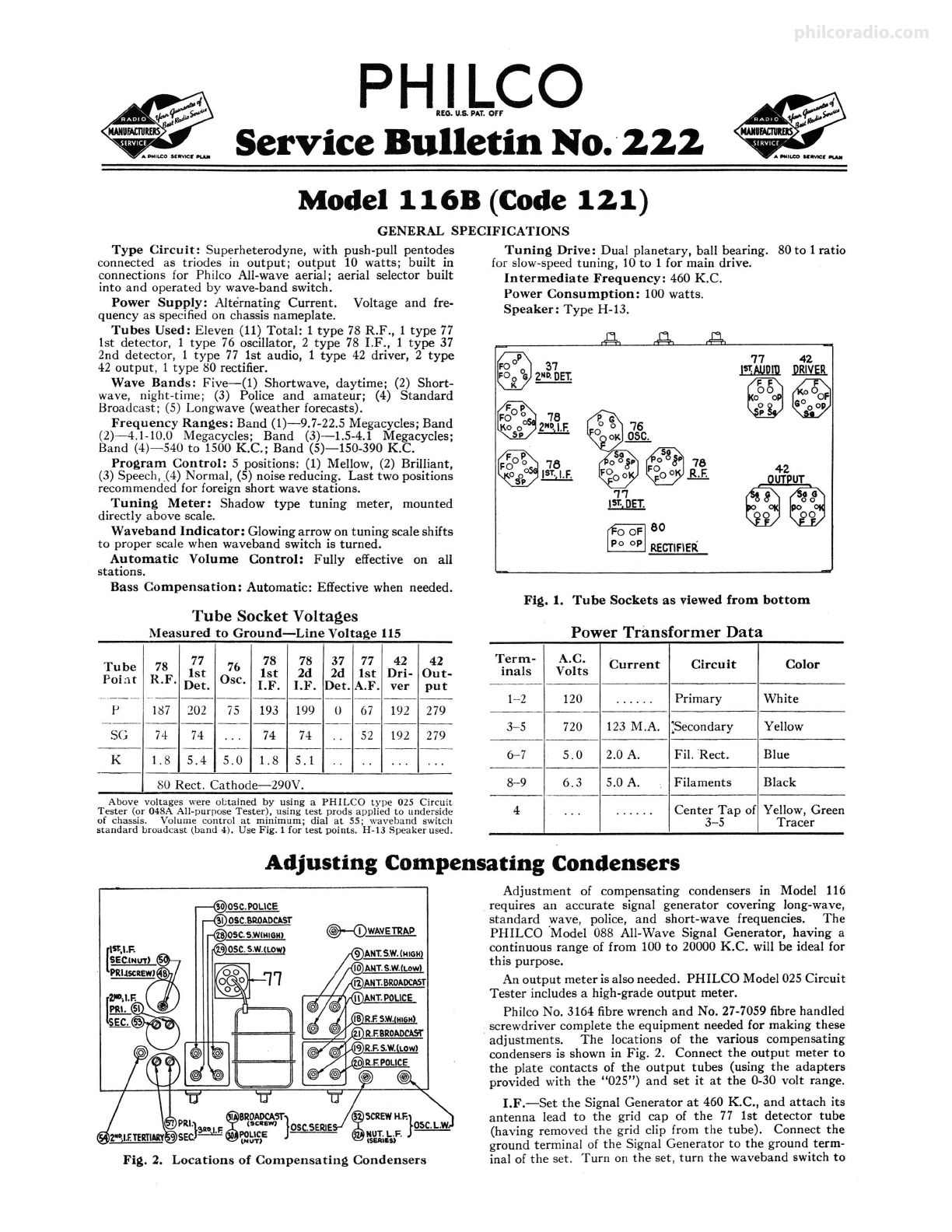
Fig. 4 Bottom View of Chassis
Description Part No.
CD Wave Trap ••....••.............••.....•.......•....••.• 38-6889
© Condenser (.00025 Mfd. Mica) ..........•.......•......... 30-1032
© Waveband Switch ...............•..........•............ 42-1118
© Transmi•sion Line Transformer ..............••........... 32-1608
© Antenna Transformer (Long Wave) ........................ 32-1729
® Condenser (.01 Mfd. Bakelite Block) ...••...•.•.•.......... 3903-SU
<D Condenser (.000015Mfd. Mica) ....•...................... !30-1030
® Antenna Transformer (Standard, Police, Short-wave) ........ 32-1735
® Compensating Condenser (Ant. S.W. High Band) ............ Part of®
@ Compensating Condenser (Ant. S.W. Low Band) ............ Part of©
@ Compensating Condenser (Ant. Police)..... . . . . . . . . . . . . . . . . Part of®
@ Compensating Condenser (Ant. Standard).... . . . . . . . . . . . . . . Part of ®
@ Condenser (.003 Mfd. Mica) .............................. 7301
0 R. F. Transformer (Long Wave) ...............••.......... 32-1730
@ Condenser (.00025 Mfd. Mica) ............................ 30-1038
@ R. F. Transformer (Standard, Police, S.W.) ................. 32-1468
@ Condenser (.002 Mfd. Mica) .............................. 30-1042
@ Compensating Condenser (R.F. Shortwave (High Band) ..... Part of 19
@ Compensating Condenser (R.F. Shortwave (Low Band) . . . . . Part of 19
@ Compensating Condenser (R.F. Police) ...............•..... Part of@
@ Compensating Condenser (R.F. Standard)..... . . . . . . . . . . . . . Part of@
0 Resistor (1000 ohms) (Brown-Black-Red) .•.•.•......••...•. 5837
0 Condenser (.05 Mfd. Tubular) ..............•.....•........ 30-4123
@ Resistor (25000 ohms) (Red-Green-Orange) ..............•.. 33-1013
@ Tuning Condenser A-Bsembly.............................. 31-1606
@ Oscillator Transformer (Long Wave) ......••............... 32-1731
@ Oscillator·Transformer (Standard, Police, Shortwave) ..•..... 32-1736
@ Compensating Condenser (Osc. S.W., High Band) ........... Part of@
@ Compensating Condenser (Osc. S.W., Low Band) ............ Part of@
0 Compensating Condenser (Osc. Police) ..................... Part of@
Oa Compensating Condenser (Osc. Police. Series) ......... Part of 31-6027
@ Compensating Condenser (Osc. Standard) .................. Part of@
@a Compensating Condenser (Osc. Standard Series) ...... Part of 31-6027
@ Compensating Condenser (Osc. Longwave) ................ · )31 6050
@a Compensating Condenser (Osc. Longwave Series)............ ·
@ Condenser (.00025 Mfd. Mica) ......................•..•.. 5858
@a Condenser (.003 Mfd. Mica) .............................. 30-1028
@ Resistor (70 ohms) (Violet-Black-Black) .................... 33-1129
@ Resistor (300 ohms Flexible) (Orange-Black-Brown) ......... 33-3010
@ Condenser (.05 Mfc!. Tubular) ............................ 30-4020
0 Condenser (.00011 Mfd. Tubular) ......................... *30-4340
@ Resistor (2 Mcgs.) (Red-Black-Green).................. . .*33-1025
~
Resistor (8000 ohms) (Gray-Black-Red) .................... 33-1114
@ Condenser (.00125 Mfd. Tubular) ............•.•.......... 30-4336
@ Resistor (70 ohms) (Violet-Black-Black) .............•...... 33-1129
@> Resistor (1000 ohms) (Brown-Black-Red) ...........••...... 5837
@ Resistor (240000 ohms 1(Red-Yellow-YeUow) ......•........ 33-1097
~~
Condenser (.05 Mfd. Bakelite Block) ...............•....... 3615-SG
List
Price
$1.00
.35
2.60
1.00
,55
,25
.35
3.60
.45
1.25
,35
2.30
.40
.20
.35
.20
5.50
55
3.50
.70
.70
.40
.35
.60
.20
.20
.35
.25
.20
.20
.25
•20
.20
.20
35
Description Part No.
Resistor (2 Mega.) (Re<l-Black-Green).................... 33-1025
Resistor (300 ohms Flexible) (Orange-Black-Black) ........ :: 33-3010
Llat
Price
$0.20
.20
.40
Condenser (.05 Mfd. Twin Bakelite Block) ..............•.. 3615-DG
C?mpensating Condenser (1st I.F. Primary).. . . . . . . . . . . . . . . Part of@
First I.F.1:ransformer ..... _.............................. 32-1642 2.00
Compensatmg Condenser (1st I.F. Secondary) .............. Part of@
Compensating Condenser (2nd I.F. Primary) .......... Part of 31-6028
Second I. F·.Transformer. . . . . . . . . . . . . . . . . . . . . . . . . . . . . . . . . 32-1734
Compensatrng Condenser (2nd I.F. Secondary) ........ Part of 31-6028
Coll?pensatrng Condenser (2nd I.F. Tertiary) ............... 04000R
Resistor (2900 ohms) (Red-White-Red) ..................... 5309
Condenser \·05 Mfd. Twin Bakelite Block) ................. 3615-DG
f~~v;,nsatrng Condenser (3rd I.F. Primary) ...•...... Part of 31-6003
r .. Tr~former ................................•.... 32-1188
Compensatrn~ Condenser (3rd I.F. Secondary) ...•.... Part of 31-6003
Con.denser (.O Mfd. Tubular) ............................ 30-4123
Resistor (1000 ohms) (Brown-Black-Red)........ . . . . . . . . . . . 5837
Resistor (51000 ohms) (Green-Brown-Orange) ...•... , ....... 33-1163
Con.denser (.00011 Mfd. Twin Bakelite Block) ...•...•.....• 8035-DG
Resistor (51000 ohms) (Green-Brown-Orange) ..••••.•......• 33-1163
Condenser (.01 Mfd. Bakelite Block) ....................... 3903-SU
.85
1.85
.85
.45
.20
.40
.45
.65
.45
.35
.20
.20
.25
.20
.25
1.45
.35
.35
.20
.20
.40
.40
.60
.30
Volume Control and On-Off Switch (See Note Below) 33-6022
Condenser (.00005 Mfd. Mica) .................•.......... 30-1029
Con.denser (.05 Mfd. Tubular) .......................••••. 30-4020
Re.s!stor (60000 ohms) (Blue-Black-Orange) .........•......• 33-1181
Resistor (330000 ohms) (Orange-Orange-Yellow) .•........... 33-1200
Condenser (004 Mfd. Tubular) ...........•............... 30-4185
Condenser (.004 Mfd. Tubular) ......•.................... 30-4185
Condenser (.003 Mfd. Mica) ....•..................•...... 30-1028
C?ndenser (.01 Mfd. Tubular) ..........• , . . . . . . . . • . . . . . . . 30-4169
Pilot Lamp (Shadow Tuning Meter) ..............•........ Part of@
Ton.e Control Switch .............................•....... 42-1119 .55
"f;"81Stor(2000 ohms) (Red-Black-Red)..... . . . ••. • . . . . . . • . • 6984 .20
ha?ow Tuning Meter. . . . . . . . . . . . . . • . . . . . . . . . • . ...•.• 45-2083 2.50
Resistor (I Meg.) (Brown-Black-Green) ...............•...• 33-1096 .20
Resistor (500000 ohms) (Yellow-White-Yellow) .........•..•. 6097 .20
Condenser (.15 Mfd. Twin Bakelite Block) ................. 6287-DG .40
Con.denser (Electrolytic-I Mfd., 3 Mfd., 2 Mfd., 1 Mfd.) •... 30-2121 2.50
Res!stor (1 Meg.) (Brown-Black-Green) .................... 4409 .20
~1Stor (70000 ohms) (Violet-Black-Orange) •••.••••........ 5385 .20
on.denser (.25 Mfd. Tubular) .........................•.. 30-4134 .45
ResJStor (100000 ohms) (White-White-Yellow) •....•........ 4411 ,20
Condenser (.00011 Mfd. Mica) .............•...•.•.••••••• 30-1031 .35
Condenser ( 05 Mfd. Bakelite Block) ...•........••.••.•...• 3615-SU .35
Resistor (160000 ohms) (Brown-Blue-Orange) •...••......•.• 33-1191 .20
Resistor (100000 ohms) (White-White-Yellow) ..••....•..... 33-1165 .20
Audio Transformer .•.........•••.••••...••.•....•••..... 32-7057 2.75
Output Transformer .•...................••..•.... , ...... 32-7078 UO
Cone and Voice Coil Assembly (H-13) ..••.•••.•.•.•.•.•.••• 02625 1.20
Field Coil & Pot Assembly (H-13) ...•...•...........•..... 36-3104 2.70
B.C: Resistor (Wirewound) (20 ohms, 110 ohms, 130 ohms) •.. 33-3021 .20
Res~tor (Wirewound) (7750 ohms).. . . . . . . . . . . . . •. •. . . • . . . 33-3020 .35
ResJStor (30000 ohms) (Orange-Black-Orange) .•..•.......... 7836 .20
Resistor (10000 ohms) (Brown-Black-Orange) .•.•..••..•...• 3524 ,20
Resistor (13000 oh=) (Brown-Orange-Orange)...... . . •. . . . . 6450 .40
Filter Choke .•......•....................•••.•.....•.... 32-7056 2.20
Condenser (.3 Mfd. Bakelite Block) ...................•.... **6287-DU .40
Condenser (Electrolytic, 8 Mfd.) ...........•......••...... H30-2025 1.35
Condenser (Electrolytic, 8 Mfd., 10 Mfd.) .••..............• 30-2045 1.80
_ [115V. 60 Cycles .•...............•.... 32-7291 7.00
@ Power Transformer{ 115 V. 25 Cycles ............•......... 32-7292 9.25
[230 V. 50 Cycles ..•••.•....•...•.....• 32-7293 6.75
~
Condenser (.015 Mfd. Twin Bakelite Block) ....•.•••.•..... 3793-DG .40
@ Resistor (10000 ohms) (Brown-Black-Orange) ••• ,. . • . •. • . ••. 3524 .20
@ Condenser (.002 Mfd. Mica) ..•..........••••...•.•....•.• 30-1042 .40
@ Pilot Lamp (Dial) ...........•................•.•..•....• 34-2039 .15
@I Condenser (.006 Mfd. Tubular) (Not shown in Fig. 4)........ 30-4125 .25
@ Condenser (.006 Mfd. Tubular) (Not shown in_Fig. 4) .... .... 30-4125 .25
Dial Scale .. ·...........•......•...........•.......•..•.• 27-6107 .40
Dial Mask and Hub A-Bsembly............•..••........•.• 31-1575 40
Dial Hub .........•.....•...•......••......••......•...• 28-7129 .10
Dial Spring Clamp ....•.••...•.•........•.•.•.•••.•. , ..•. 28-2837 .10
Socket--4-Prong ...•.....•..••....•.••......••.•.••..•.. 27-6042 .10
Socket-5-Prong ....................•....•.•.•.......... 27-6035 ,11
Socket-o-Prong ....•...•.•....................•.•.•...• 27-6036 ,11
Speaker Plug Socket. . .. . . • . . . . . . . •. . . . •• . •. . . •• . . . . . . • . . 27-6033 .08
Knob (Volume, Tone Waveband) ......•..............•.... 27-4208 .10
Knob (Station Selector) .................••...••..•.••.•.. 27-4206 .12
Knob (Slow Speed) ...............•.......•.•..•.•..•.•.• 27-4207 .10
Tube Shield......... . . . . . •. . . . . . . . . . . . . . . •. . . ••• . •. . . . . . 28-2726 .10
Tube Shield Base.. ..•. . •. . •. . . ••. . . . . . . . • . •. . . . . . . . . . . . • 28-2725 .03
A.C. Cord & Plug .............••...•..•.•........•.•.•.• L-943A .60
1:::1ai,;;.-.-.:::::::::::::::::::::::::::::::::::::::::::~tmi ::
Chassis Mtg. Bolt .......................•......• , ....... W-1496 1.60perC
ChassJBMtg. Washer (Rubber) ...........••..........•.... 27-4201 1.40 per C
Chassis Mtg. Bumper (Rubber). .........•..........•..... 27-4200 3.75perC
*Mounted on top of chassis•
tMounted inside @.
**In 25-cycle model, this is part No. 04357.
Hin 25-cycle model, this is part No. 30-2026
Note: Volume Control is 2 meg., tapped at 400,000 ohms
philcoradio.com
Page4 PH ILCO
Service Bulletin No. 222
standard broadcast (second position from left) and set dial
at 55. Turn condenser@ (2nd I.F. tertiary) all the way down
before adjusting the other I.F. Compensators. Now with the
fibre screwdriver, adjust condensers @)and ® (3rd I.F.), @
and@ (2nd I.F.), and then@) and@ (1st I.F.) until maximum
reading is obtained in the output meter. Turn down the
"attenuator" on the signal generator if the output meter
needle goes off the scale. Now adjust condenser@ (2nd I.F.
tertiary for maximum reading).
WAVE TRAP-Connect the Signal Generator antenna and
ground leads to the antenna and ground posts of the set.
Replace the grid clip on the 77 tube cap. With the signal
generator operating at 460 K.C. and the set controls adjusted
as for I.F., adjust wavetrap © until the minimum reading is
obtained in the output meter.
SHORTWAVE (DAYTIME BAND)-Turn wave band
switch to the shortwave (daytime) position (extreme right).
Set signal generator at 18 megacycles and dial of set at 18.0
(top scale). Now adjust the oscillator, Antenna, and R.F.
shortwave compensators in turn, for maximum reading. These
are@,® and @ respectively.
SHORTWAVE (NIGHT-TIME BAND)-Turn the wave-
band switch to position 4 (counting from the left). Set the
signal generator and receiver at 9.5 megacycles and adjust the
oscillator, antenna and R.F. compensators respectively, in
this band for maximum reading. These are @, @)and @.
POLICE AND AMATEUR BAND-Tum the waveband
switch to position 3. Set the dial and sii:-nalgenerator at 4.0
megacycles and adjust condensers @),@ and @ respectively
for maximum reading.
Set the signal generator at 1600 K.C. and turn the dial to
1.6. Adjust condenser @a (nut), oscillator police series, to
maximum reading.
STANDARD BROADCAST BAND-Tum the waveband
switch to position 2 (from left). Set the dial and signal
generator at 1500 K.C. and adjust condensers®• @ and ®
for maximum reading.
Set the dial and signal generator at 600 K.C. and adjust
condenser ®a (screw), broadcast series, for maximum reading.
LONGWAVE BAND-Tum waveband switch to position
1 (left). Set the dial and signal generator at 340 K.C. and
adjust condenser @ (screw) to maximum. This is the upper
end of the longwave (low frequency) band. Finally, set the
dial and signal generator at 175 K.C. and adjust condenser
@a (nut) for maximum reading. This is the lower end of the
longwave band.
* THE FINEST COMPLETE PORTABLETEST UNIT.
... a PHILCOProduct
MODEL 099
Combination
All-Wave Signal Generator
and
Circuit-Tester
• Combines the PHILCO pre-
cision All-wave signal generator
Model 088, having many ad-
vanced exclusive features, and
the world-famous PHILCO cir-
cuit tester, Model 025. This new
Universal Portable Test Unit
meets every requirement of the
Serviceman - R.M.S. member. Model 099-In Walnut Case with Removable Lid
• Ownership of this unit establishes the Serviceman as a discrimina-
ting user of Highest Quality Equipment, capable of Precision Tests.
All-Wave Fundamental Frequency Signal Generator, 110-20000 K.C. • Circuit-Tester includes Output Meter
and facilities for testing Voltage, Current, Resistance and Capacity • All leads and adapters included.
MODEL 099, Complete ...... List $100.00
Subject to Serviceman's Discount
PHILCO RADIO & TELEVISION CORPORATION
June, 1935 Parts and Service Division Printed in U.S. A,
philcoradio.com

Other manuals for 121

8

This manual suits for next models

1

Other Philco Radio manuals

Philco 37-116 User manual

Philco

Philco 37-116 User manual

Philco 116 User manual

Philco

Philco 116 User manual

Philco 16 Reference manual

Philco

Philco 16 Reference manual

Philco 37-630 User manual

Philco

Philco 37-630 User manual

Philco 611 User manual

Philco

Philco 611 User manual

Philco 121 User manual

Philco

Philco 121 User manual

Philco D-592 User manual

Philco

Philco D-592 User manual

Philco 15 Series Reference manual

Philco

Philco 15 Series Reference manual

Philco 37-60 User manual

Philco

Philco 37-60 User manual

Philco PRR1005BT User manual

Philco

Philco PRR1005BT User manual

Philco 96 User manual

Philco

Philco 96 User manual

Philco 28 User manual

Philco

Philco 28 User manual

Philco 650 User manual

Philco

Philco 650 User manual

Philco PHOTOFACT 49-1150 User manual

Philco

Philco PHOTOFACT 49-1150 User manual

Philco 121 User manual

Philco

Philco 121 User manual

Philco 66 User manual

Philco

Philco 66 User manual

Philco 37-660 User manual

Philco

Philco 37-660 User manual

Philco 144 User manual

Philco

Philco 144 User manual

Philco CSP790BC User manual

Philco

Philco CSP790BC User manual

Philco 118 User manual

Philco

Philco 118 User manual

Philco 80 User manual

Philco

Philco 80 User manual

Philco 200 User manual

Philco

Philco 200 User manual

Philco 37-670 User manual

Philco

Philco 37-670 User manual

Philco 37-675 User manual

Philco

Philco 37-675 User manual

Popular Radio manuals by other brands

Alinco DR-235 Service manual

Alinco

Alinco DR-235 Service manual

Konig HAV-IR20 manual

Konig

Konig HAV-IR20 manual

Ritron RPM-150 user guide

Ritron

Ritron RPM-150 user guide

TERSUS RS400H3-H user manual

TERSUS

TERSUS RS400H3-H user manual

Listen Technologies Satellite Radio user manual

Listen Technologies

Listen Technologies Satellite Radio user manual

Albrecht AE 4200 R Service manual

Albrecht

Albrecht AE 4200 R Service manual

TZS First AUSTRIA FA-1907-1 instruction manual

TZS First AUSTRIA

TZS First AUSTRIA FA-1907-1 instruction manual

Heath Heathkit AR-14 Schematic diagram

Heath

Heath Heathkit AR-14 Schematic diagram

Raymarine Ray230 Owner's handbook

Raymarine

Raymarine Ray230 Owner's handbook

Exalt S Series Installation and management guide

Exalt

Exalt S Series Installation and management guide

P Tec CASTOR user manual

P Tec

P Tec CASTOR user manual

GME TX4500 instruction manual

GME

GME TX4500 instruction manual

Zastone ZT-V9 manual

Zastone

Zastone ZT-V9 manual

SOUNDMASTER RCD1755 manual

SOUNDMASTER

SOUNDMASTER RCD1755 manual

Sony CFD-S47 - Cd Radio Cassette-corder Service manual

Sony

Sony CFD-S47 - Cd Radio Cassette-corder Service manual

Clarion SIRHM Home installation guide

Clarion

Clarion SIRHM Home installation guide

Exalt EX-5r GigE Installation & Management

Exalt

Exalt EX-5r GigE Installation & Management

National Instruments USRP-2950 Getting started guide

National Instruments

National Instruments USRP-2950 Getting started guide

manuals.online logo
manuals.online logoBrands
  • About & Mission
  • Contact us
  • Privacy Policy
  • Terms and Conditions

Copyright 2025 Manuals.Online. All Rights Reserved.