Viso Systems LightSpion User manual

VISO SYSTEMS
LightSpion Extender
User Guide
Revision: 2020-11

Congratulations on purchasing your new Viso Systems LightSpion Extender. Before
using this product, please read the Safety Information.
This manual contains descriptions and troubleshooting necessary to install and
operate your new Viso Systems product. Please review this manual thoroughly to
ensure proper installation and operation.
For news, Q&A and support at Viso Systems, visit our website at
www.visosystems.com
Other manuals in this series for which the latest version can be downloaded from
www.visosystem.com, include:
▪LightSpion User manual
▪Light Inspector User Guide (Software)

3
Contents
1. Safety Information.................................................................................. 4
1.1. Preventing electric shocks.......................................................................................4
2. Disposing of this Product ........................................................................ 4
3. Introduction ........................................................................................... 4
About the LightSpion Extender.....................................................................................4
About this document ....................................................................................................4
4. Dimensions............................................................................................. 5
5. Packaging and weight ............................................................................. 6
5.1. Extender Package Content ......................................................................................6
6. Shipping Packages .................................................................................. 7
7. Installation ............................................................................................. 7
7.1. LightSpion Case Plate and Slider Plate.....................................................................7
7.2. Installing the Gonio Base ........................................................................................ 7
8. Configuration ......................................................................................... 9
Long configuration........................................................................................................9
Short configuration.......................................................................................................9
LightSpion alignment ..................................................................................................10
9. Connecting the Extender....................................................................... 10
10. Mounting a Light Source ....................................................................... 12
10.1. Lamp Alignment.................................................................................................... 12
11. Center of Light Sources ......................................................................... 14
12. Lamp connection .................................................................................. 16
13. Making measurements ......................................................................... 16
14. Stray Light Corrections.......................................................................... 16
15. Specifications ....................................................................................... 17
Physical dimensions....................................................................................................17
Warranty.....................................................................................................................17
Ordering information..................................................................................................17
4
1. Safety Information
Warning! This product is not for household use.
Read this manual before installing and operating the LabSpion, follow the safety
warnings listed below, and study all the cautions in the manual.
1.1. Preventing electric shocks
Make sure the power supply is always grounded.
Use a source of AC power that complies with the local building and electrical codes,
that has both overload and ground-fault protection.
If the controller or the power supply are in any way damaged, defective, wet, or
show signs of overheating, disconnect the power supply from the AC power and
contact Viso Service for assistance.
Do not install or use the device outdoors. Do not spray with or immerse in water or
any other liquid.
Do not remove any covers or attempt to repair the controller or the power supply.
Refer any service to Viso.
2. Disposing of this Product
Viso Systems products are supplied in compliance with Directive 2012/19/EU on
waste - electrical and electronic equipment (WEEE) together with the RoHS Directive
2011/65/EU with amendments 2015/863. Help preserve the environment! Ensure
that this product is recycled at the end of its lifetime. Your supplier can give details of
local arrangements for the disposal of Viso Systems products.
3. Introduction
About the LightSpion Extender
The LightSpion Extender expands the ability of LightSpion to measure the light
sources with a diameter of up to 220mm. The device is easily connected to the
previously installed LightSpion and gets detected by the Light Inspector software
automatically.
About this document
These guidelines describe the installation process of the LightSpion Extender and the
alignment of light sources to be measured.
© 2007 Viso Systems ApS, Denmark
All rights reserved. No part of this manual may be reproduced, in any form or by any means,
without permission in writing from Viso Systems ApS, Denmark. Information subject to change
without notice. Viso Systems ApS and all affiliated companies disclaim liability for any injury,
damage, direct or indirect loss, consequential or economic loss or any other loss occasioned by
the use of, inability to use or reliance on the information contained in this manual.

5
4. Dimensions
6
5. Packaging and weight
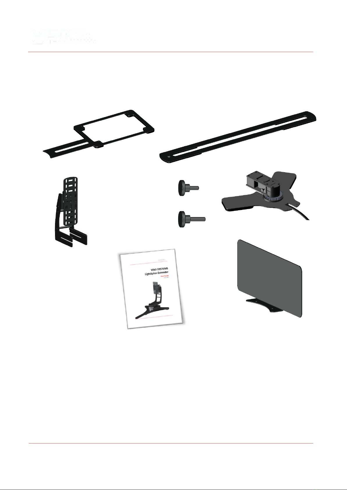
5.1. Extender Package Content
▪Case Plate
▪Slider Plate
▪Tower
▪Base
▪Straylight Plate /Slider plate
▪5 x M4x10 Thumb screws
▪2 x M4x16 Thumb screws
▪User Guide
5 x M4x10 Thumb screws
2 x M4x16 Thumb screws
7
6. Shipping Packages
Shipping packages
Shipping dimensions
CBM
Weight
1
Extender
106 x 35 x 22 cm
0.082
9 kg
Total shipping weight: 9 kg.
The shipment is done in a total of 1 package
7. Installation
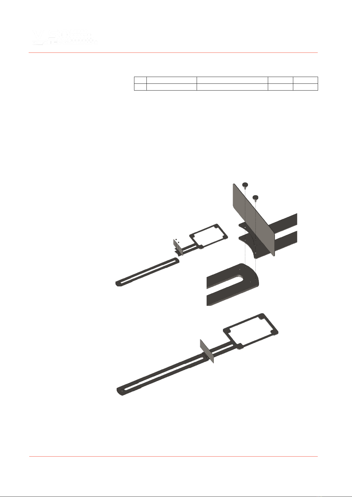
7.1. LightSpion Case Plate and Slider Plate
Assemble the Case Plate and Slider Plate with 2 x M4x10 thumb screws supplied with the
Extender
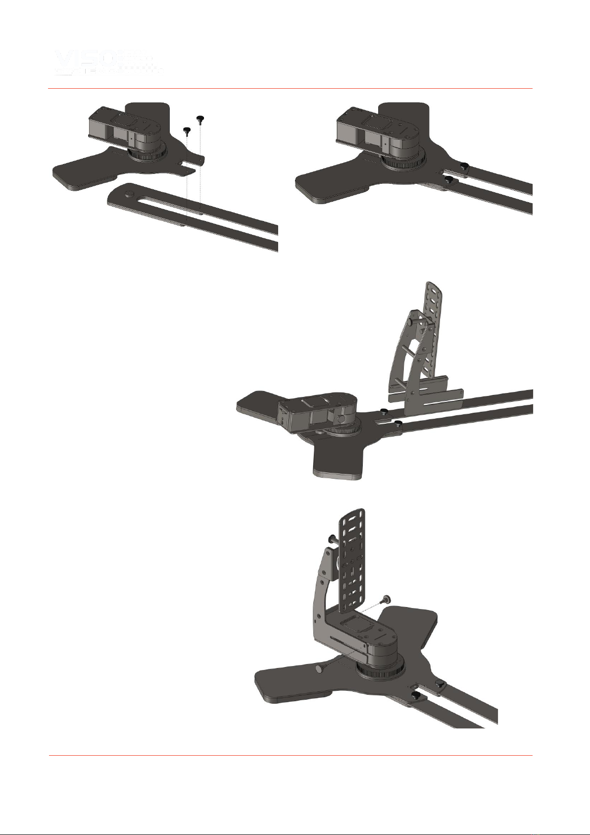
7.2. Installing the Gonio Base
The Base is installed using the supplied 2 x M4x10 thumb screws. Slide the Base into
the Slider plate and fix with the two screws.
8
Slide on the tower from the front
Mount the two M4x16 thumb screws for locking the Tower
9
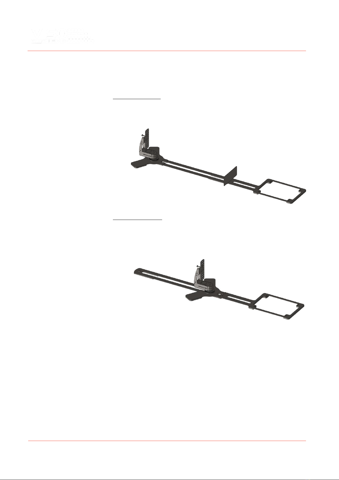
8. Configuration
The Extender Base can be set in two positions depending on the light source to
measure.
Long configuration
The full goniometer-sensor length of 181 cm allows the measurements of light
sources up to 220 mm in diameter
Short configuration
The reduced goniometer-sensor length of 114 cm allows the measurements of light
sources up to 135 mm in diameter. This configuration can be useful when measuring
smaller light sources and/or of low power, where a shorter distance will increase the
sensitivity of the sensor. In this position you should remove the Straylight Plate.

10
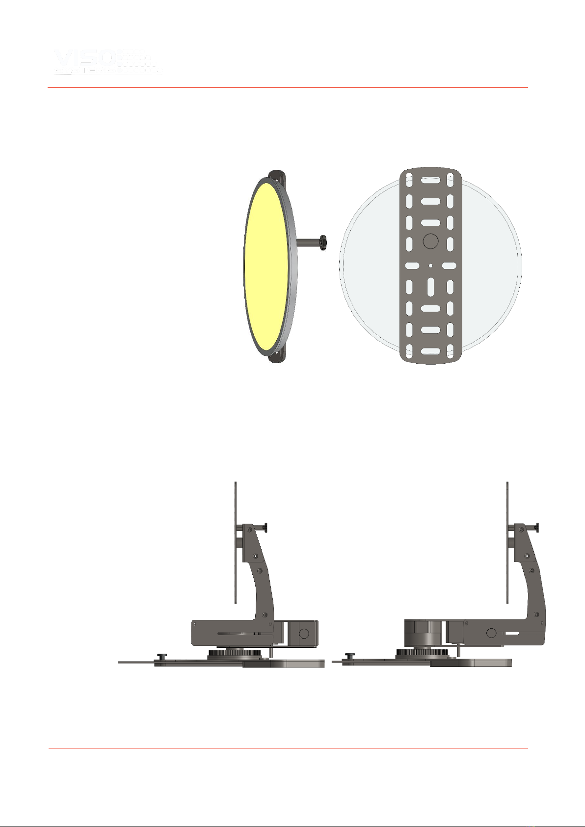
LightSpion alignment
The Extender base plate comes with alignment points and a visual outline for the
LightSpion ensuring that the LightSpion is fixed at the right location for accurate
measurements.
The alignment points clicks into bottom of the LightSpion as shown below
9. Connecting the Extender
The extender is connected via
unplugging the built-in
goniometer and connecting the
RJ45 of the Extender goniometer.
The power going to the built-in
goniometer lamp holder must
also be unplugged and connected
to the Extender instead.

11
The Light Inspector software will automatically detect the Extender. Various
configurations can be seen in the photometric window.
Long configuration:
Short configuration:
In case the system does not detect the Extender, it is possible to select it manually
in:
Setup -> Options.
12
10. Mounting a Light Source
The vertical alignment of the light source is done automatically by the centered twin
clamp holder.
10.1. Light Source Alignment
The photometric center of the light source must be centered vertically on the
rotation axis of the goniometer. This is done by sliding the Tower. Loosen the two
thumb screws and slide the Tower to the wanted position. The Tower can be slid
from 0 to 140 mm
Minimum
Maximum
13
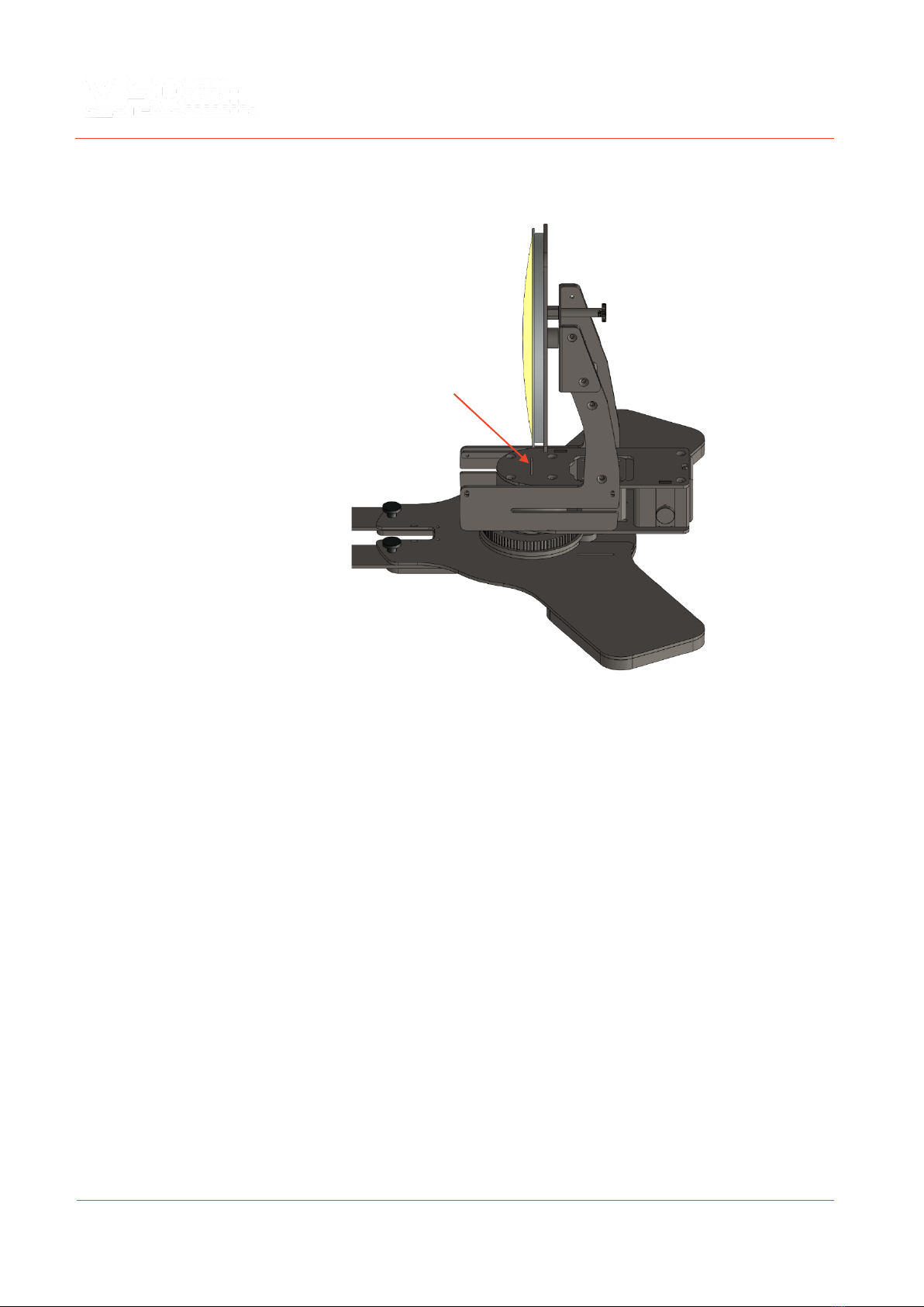
The horizontal position of the light source should be placed in such a way so that the
illuminating part is at the center of rotation, as shown below. The center of rotation
is marked with a slit in the top plate.
Important: Failing to align the light source to the center of rotation can affect the
accuracy of the peak intensity value and the beam angle.
The flux value is not affected by the incorrect horizontal placement.
Guidance on how to establish the photometric center of a light source can be found
in the next section.
14
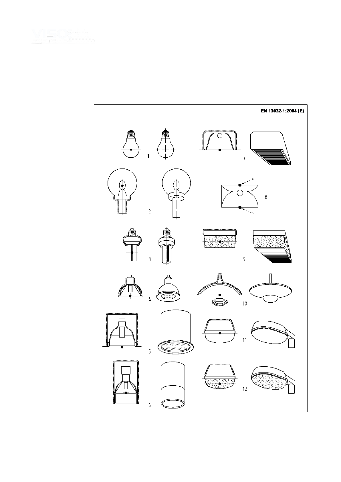
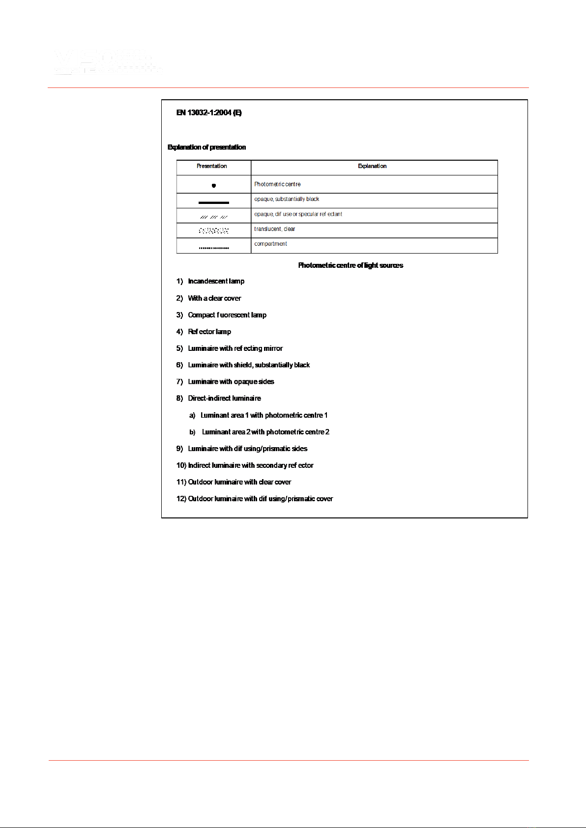
11. Center of Light Sources
Photometric center
The black spot marks the photometric center of the different light sources. This
photometric center is what should be aligned with center of rotation of the Base.
15

16
12. Light source connection
The measured light source is connected using an all-purpose power connector placed
on the back of the goniometer base, as shown below.
13. Making measurements
The LightSpion Extender measurements are done in the exact same way as in the
case of LightSpion.
Please refer to the LightSpion user manual for further details.
When measuring linear tubes, their width should not exceed half of the maximum
diameter of light sources for the Extender, namely 220 cm. That means the
maximum width of the tubes is 110 cm.
14. Stray Light Corrections
Sometimes when measuring specific light sources,
you can observe reflections in the black surface of
the extender plate, adding to the amount of light
detected by the sensor. Such an example is shown
in the picture to the right:
To avoid the unnecessary the false light /stray
light, remember to use the Straylight Plate in the
long configuration.
Also follow instructions in the Viso guidelines
called: “Guidelines - Building a Lighting
Laboratory”
Stray light

17
15. Specifications
Physical dimensions
Shipping dimensions (L x W x H) .........................................................106 x 35 x 22 cm
Shipping Weight....................................................................................................... 9 kg
Dimensions (L x W x H) .................................................................166 (99) x 43 x 31 cm
Weight ..................................................................................................................... 7 kg
Sensor distance..................................................................................... 114 and 181 cm
Light source diameter range.........................................................................0 - 220 mm
Linear light source depth range ....................................................................0 - 140 mm
Light source maximum weight................................................................................. 4 kg
Warranty
Warranty period ................................................................................................. 2 years
Ordering information
LightSpion Extender..............................................................................P/N EXLIGSP002
18
At Viso Systems we design, develop and manufacture OEM- and customer-specific
goniophotometer solutions. Our mission is to support customers with powerful and
yet easy to use control measurements solutions. Products are developed and
manufactured in Copenhagen, Denmark.
Other manuals for LightSpion
1
Table of contents


