Visonic SP-5A User manual

DE6113 1
SP
SPSP
SP-
--
-5A
5A5A
5A
Multi-Channel Speech Processor
Installation Instructions
1. INTRODUCTION
1. INTRODUCTION1. INTRODUCTION
1. INTRODUCTION
1.1 Description and Capabilities
The SP-5A is an advanced 4-channel record/playback device for
short voice messages. A different message can be recorded on
each of the 4 "channels", and each channel can be played back
separately by triggering the corresponding input. A unique design
feature allows the number of messages at one site to be
increased virtually without limit by cascading any number of SP-
5A units (Para. 1.6).
The total available recording time for all 4 messages is 90
seconds. For maximum efficiency, each outgoing message can
be composed of a short "individual" message (alarm, fire, etc.)
and a longer "common" message (location, address or alert
signal). The common message can be joined to the beginning or
the end of each individual message, as desired. Upon triggering
one of the 4 channel inputs, the relevant individual message and
the common message are played back in succession, in the
order chosen (Para. 1.3B), and in accordance with the selected
playback mode (Para. 1.3C).
The SP-5A provides 1-Watt audio output that can be applied to a
loudspeaker, or to the Visonic Ltd. 10 W power amplifier AMP-10,
or to a dialer that has special speech processor input. The unit may
be used for verbal reporting of burglar or fire alarms and for making
access control systems and vending machines "speak out". It may
also provide automatic playback of warnings, announcements,
guidance and advertisements in elevators, stairwells, corridors,
exhibitions, museums, etc.
Playback from each channel can be triggered by motion detectors
or any type of momentary or on/off switch. The channel inputs
can function with normally open or normally closed switches
(Para. 1.4A).
A microphone, RECORD pushbutton, volume control potentio-
meter and LED status indicator are included on board (Fig. 1). An
audio source selector permits the installer to choose between
recording speech directly with the internal microphone or using a
pre-recorded message from an external audio source such as a
tape recorder. The SP-5A recognizes priority levels and will
therefore interrupt a lower priority message in favor of a higher
priority message (Para. 1.4B).
The SP-5A is suitable for mounting within a host system cabinet
or inside a loudspeaker housing. Two units may be mounted in
an optional plastic cabinet - model UPB-3. Operating power is
drawn from the host system or from an external 12VDC supply.
1.2 Message Structure
The SP-5A can store four separate individual voice messages
plus a common message linked to all 4 channels. The overall
recording time must not exceed 20 seconds (or 90 seconds as an
option). The common message may be used to indicate the
location of the particular SP-5A or to identify its user or to play an
alert signal. The 4 individual messages provide information
associated with the specific channel inputs.
Suppose the SP-5A is installed in an imaginary warehouse
known as Acme Storage and wired to report verbally via an
automatic dialer. Four distinct alarm messages could be recorded
for transmission and linked to a common message, as
demonstrated in the following example:
Chan. Combined Message (common + individual)
1Acme Storage, fire alarm
2Acme Storage, intrusion alarm
3Acme Storage, flooding alarm
4Acme Storage, power failure
In this example, the common message is "Acme Storage". The
individual messages relate to the type of alarm associated with
particular channel input.
Memory space (recording time) can be divided freely between the
four individual messages and the common message, provided
that the total accumulated recording time of all 5 messages will
not exceed the 20-second time limit. Omitting a certain channel
message or the common message will leave more memory space
for the rest of the messages.
SP–5A
N.C. N.O.
MIN
MAX
+
–
GNDCH1CH2CH3CH4DISACTBSYGNDSPK12 V
1234
ON
1234
ON
+–
MICRO-
PHONE RECORDING
SOURCE JUMPER
VOLUME
CONTROL
RECORD
BUTTON
FUNCTION
CONTROL
SELECTOR
AUDIO
CHANNEL
SELECTOR
INPUT
POLARITY
JUMPER
STATUS
LED
Figure 1. PC Board Layout
1.3. Selectable Functions
Figure 2 presents the Function Control 4-lever DIP switch. The
tasks of all four switches are explained in the following sub-
paragraphs.
A. Play/Record (SW1)
The PLAY/REC switch (marked 1) enables
you to determine the standby state of the SP5.
ON: The unit will stand by for recording (see
Section 4 for recording procedure).
OFF: the unit will stand by for playback.
Playback will start if channel input is triggered,
or a channel DIP switch is set to ON.
B. Playback Order
The COM MSG switch (marked 2) determines
which part will be played back first: the indivi-
Figure 2.
Function
Control Switch
dual channel message or the common message.
ON: The common message will be played back first, and then the
individual channel message.
OFF: The individual channel message will be played back first,
and then the common message.
C. Playback Mode (SW3, SW4)
The PLAY MODE / MEMORY ERASE selectors (levers 3and 4
of the Function Control switch) can be set to four different
combinations as follows:
3 4 Resultant Mode
ON ON Erase mode - all recordings are erased (if REC
button is pressed 3 times*).
OFF OFF Single playback (non repeating) in response to
momentary or continuous triggering of any input.
ON OFF Repeated playback with timeout after 3 minutes,
in response to momentary or continuous
triggering of any input.
OFF ON Repeated playback for as long as the channel
input is kept triggered, but subject to the 3-
minute timeout.
*The button must be pressed for at least 1/2 second each time -
all within 4 seconds.

2DE6113
1.4 Input Channel Characteristics
A. Input Polarity Definition
All 4 channel inputs, CH1 through CH4, can be programmed to
function as Normally Closed (N.C.) or Normally Open (N.O.), by
changing the position of the on-board input polarity jumper (see
Figure 1).
B. Channel Priorities
Each channel has a priority level commensurate with its number.
This means that channel 1 has the highest priority and channel 4
has the lowest priority.
For example, if CH2 is triggered while Channel 1 is engaged in
playback, Channel 2 will have to wait until Channel 1 times out.
Conversely, if Channel 1 is triggered while Channel 2 is engaged
in playback, Channel 2 will become disabled on the first pause
between message repetitions, and Channel 1 will take over (will
start its own playback).
1.5 The Channel Selector
The CHANNELS selector allows you to select the channel into
which you are going to record a message. It also allows you to
initiate a test playback from each channel (see Para. 4.3). The
various settings possible with the four switch levers are:
"1" ON and the rest OFF - Channel 1 is selected
"2" ON and the rest OFF - Channel 2 is selected
"3" ON and the rest OFF - Channel 3 is selected
"4" ON and the rest OFF - Channel 4 is selected
"1", "2", "3" and "4" ON - All four channels are selected for
recording the common message.
1.6 The Control Terminals
In applications requiring more than four audio channels, several
SP-5A units may be installed to operate harmoniously into the
same loudspeaker or into the same communicator device. This is
possible by virtue of 3 special control terminals that play a very
important role in multi-unit configurations (Fig. 3). The control
terminals are:
DIS - DISABLE input. If pulled LOW (grounded) by an external
circuit, this terminal disables the SP-5A.
ACT - ACTIVE output. This terminal, which is normally HIGH, is
pulled LOW by internal circuitry in the following cases:
– While the SP-5A is engaged in playback.
– While the SP-5A is disabled via its DIS input.
– While the SP-5A stands by because the BUSY line indicates
that the audio amplifier is currently engaged in amplifying speech
played back by another SP-5A unit.
BSY - BUSY Input/Output terminal. While an SP-5A is engaged
in playback, its BSY terminal is pulled to ground by internal
circuitry, to indicate that a message is being played back into the
speaker. The other SP-5A units sense this indication via their
own BSY terminals (Fig. 3).
1ST SP-5A UNIT
(PLAYS BACK)
2ND SP-5A UNIT
(DISABLED)
3RD SP-5A UNIT
(DISABLED)
SPK
DIS ACT BSY DIS ACT BSY DIS ACT BSY
SPK SPK
AUDIO OUTPUT CIRCUIT
"BUSY" LINE
"DISABLE" "DISABLE"
GND GND GND
Figure 3. Multi-Unit Configuration
In the example of Figure 3, the first SP-5A unit has higher priority
than other units, because it can not be disabled (its DIS input is
not connected). When it starts playing back, its ACT output goes
LOW and disables the second unit, which in turn disables the
third unit and so on. Suppose the 2nd unit is triggered into
playback before the 1st unit. In the course of this playback, the
first unit can also be triggered into playback. The BUSY line
informs the first unit that the system is busy. However, when the
2nd unit pauses between message repetitions, the first unit
senses the momentary release of the BUSY line and starts
playing back. Simultaneously, the first unit's ACT output disables
all other units to prevent them from taking over at the first pause.
2. SPECIFICATIONS
2. SPECIFICATIONS2. SPECIFICATIONS
2. SPECIFICATIONS
Maximum Recording Duration: 90 sec
Memory Type: EEPROM (no need for battery backup)
Number of Audio Channels: 4
Channel Input Types: N.O. or N.C., jumper selected
Control Terminals:
BSY - Normally HIGH Input/output. Goes LOW while the SP-5A
plays back a message. Prevents playback if pulled LOW externally.
IS - Normally HIGH input. Disables the SP-5A if pulled LOW
(disable takes effect only when pausing between message
repetitions).
ACT - Normally HIGH output. Goes LOW during playback, or
when the DIS input is LOW, or while the SP-5A waits for release
of the BSY line.
Interval between Message Repetitions: 2 seconds
Loudspeaker Output: 1W across 8Ω(attenuated to 1 V p-p
max. if the VOL control is set to MIN.)
External Audio Input: 100 mV p-p max./ 4 kΩ
Supply Voltage: 12 VDC ± 15%
Current Consumption: 10 mA (standby), 30 mA (record), 300 mA
peak (playback into loudspeaker).
Operating Temp.: 0°C to 50°C (32°F to 122°F)
Size: SP-5A: 70 x 74 x 16.5 mm (2-3/4 x 2-7/8 x 5/8")
UPB-3 (optional): 165 x 108 x 38 mm (6-1/2 x 4-1/4 x 1-1/2 ")
Weight: SP-5A: 48 g. (1.7 oz),
UPB-3 (optional): 154 g. (5.4 oz)
3. INSTALLATION
3. INSTALLATION3. INSTALLATION
3. INSTALLATION
The SP-5A is supplied as a module without a case, for installation
within a host system cabinet. It may be also installed in an
optional UPB-3 plastic housing that can accommodate two side-
by-side SP-5A units or a single unit, as desired (Para.3.2)
3.1 Mounting an Unpacked SP-5A
Mounting the SP-5A module within a host system cabinet is
simple, by using the mounting holes at the 4 corners of its printed
circuit board (Fig. 4).
Be sure to leave at least 6 mm clearance between the bottom of
the PCB and any metallic chassis. This is easily achieved by
inserting plastic standoffs over the mounting screws, to serve as
spacers between the printed circuit board and the chassis.
3.2. Mounting in the UPB-3 Cabinet
If your wish to use a UPB-3
cabinet for mounting two SP-5A
modules, refer to Figures 5, 6
and 7 and proceed as follows:
.
Remove the screw that
secures the UPB-3 cover to
the base.
.
Insert a small screwdriver
blade into the slot near one
of the snap-in tabs, as
shown. Carefully flex the
GNDCH1CH2CH3CH4DISACTBSYGNDSPK12 V
+–
SP-5A
Ø 3.2 m
(1/8")
66.5 mm
(2-5/8")
62.6 mm
(2-15/32")
Figure 4. Mounting Hole Plan

DE6113 3
cover edge out, until the cover disengages from the tab. Repeat
this with the other tab to free the cover completely.
C. Lift the free edge of the cover diagonally up and get the other
edge free by pulling it backwards to disengage the tabs at the
back.
D. Hold the base against the mounting surface and mark the
points for drilling.
E. Drill the mounting holes and insert wall anchors (if necessary).
Insert the wires into the base through the wiring holes. Attach
the base to the mounting surface with the two long screws.
Figure 5. Optional UPB-3 Cabinet, Cover Removal
Figure 6. Mounting and Wiring Provisions
SP–5A
N.C. N.O.
MIN
MAX
+
–
GNDCH1CH 2CH3CH4DISACTBSYGNDSPK12 V
1234
ON
1234
ON
+–
SP–5A
N.C. N.O.
MIN
MAX
+
–
GNDCH1CH2CH3CH4DISACTBSYGNDSPK12 V
1234
ON
12
34
ON
+–
MODULE HOLD-DOWN SCREWS
Figure 7. Dual Module Setup in UPB-3 Cabinet
F. Put the SP-5A modules in place as shown in Figure 7 (with
the bottom edge seated in the module edge support). Align
the holes in the top part of the PCB with the plastic stand-off
in the base. Secure the modules to the base with the short
hold-down screws.
3.3 Wiring a Single Unit
Refer to Figure 8 and perform the following steps:
A. Verify that the input polarity jumper (N.C./N.O.) is mounted on
the desired pair of pins, depending on the type of switches
used to trigger the SP-5A.
B. Connect each triggering device across its respective input
(CH1, CH2, CH3, CH4) and one of the ground (GND) terminals.
Note: Dry contact or open-collector triggering devices may be
used.
C. Connect a 1-Watt loudspeaker across the SPK and GND
terminals. Optionally, you may connect an audio power
amplifier or a dialer audio input.
GNDCH1CH2CH3CH4DISACTBSYGNDSPK12 V
+–
SEE FIG. 3
LOUDSPEAKER
12 VDC
POWER
SUPPLY
+–
SP-5A TERMINAL BLOCK
Figure 8. Wiring the SP-5A
Important! For driving an amplifier or a dialer, you can
attenuate the audio output level to 1 V p-p by turning the
volume control (VOL) all the way down to MIN. (minimum).
D. Do not make any connections to the BSY, ACT and DIS
terminals. However, the BSY terminal may be used to
mute/activate an external audio amplifier driven by the SP-5A
audio output.
E. Connect a nominal 12 VDC power source across the 12VDC
(+) and (–) terminals, making sure not to reverse the polarity.
3.4 Wiring a Multi-Unit Configuration
A. Perform steps A and B in Para. 3.3 above.
B. Interconnect all BSY terminals, all GND terminals and all SPK
terminals (Fig. 3).
Note: The BSY line can be used to mute/activate an external
audio amplifier driven by all SP-5A units in parallel.
C. Select the SP-5A units to which you wish to assign priority.
Leave the DIS terminal of this unit disconnected (Fig. 3).
D. Connect a wire between the ACT terminal of the first (high
priority) unit to the DIS terminal of the second unit. Connect
the ACT terminal of the second unit to the DIS terminal of the
third unit, and so on. Do not connect anything to the ACT
terminal of the last unit.
E. Connect a nominal 12 VDC power source across the 12VDC
(+) and (–) terminals of all SP-5A units, making sure not to
reverse the polarity.
Note: Once an SP-5A unit is disabled via its DIS terminal, its
indicator LED flashes slowly.
4. PREPARATION AND TESTING
4. PREPARATION AND TESTING4. PREPARATION AND TESTING
4. PREPARATION AND TESTING
4.1 Erasing All Previous Recordings
This procedure is important if the SP-5A unit has been used
before in another application, or tested on the installer's bench.
Total erasure will remove the previous "memory partition table",
allowing you to freely re-divide the recording time between the
channel messages and the common message.
A. Set levers 3and 4of the Function Control switch to ON, and
verify that lever 1 is set to OFF.
B. Press the REC button 3 times in succession (keep the button
down at least 0.5 seconds each time). There is a 4-second
timeout for this operation. If done properly, the on-board LED
will flash rapidly for half a second to indicate successful erasure.
C. Select the non-repeating playback mode by setting levers No.
3and 4of the Function Control switch to OFF. This mode is
required for later testing (para. 4.3).
4.2 Recording New Messages
To record with the on-board microphone, verify that the recording
source jumper is mounted across the two INT pins of the
recording source header.
Note: To make a good recording with the microphone, turn off
nearby radio receivers and noisy machines, and ask people near
you to keep silent while you record. Speak at normal voice level
about 50 cm from the microphone, but get closer to the
microphone if background noise is too high.

4 DE6113
To record a signal from an external audio source, remove the
jumper from the INT position and connect the external audio source
across the EXT (+) and (–) pins. However, a correct signal level is
required for making a good quality recording. For instance, you
could record from the loudspeaker output of a portable tape player,
provided that you turn the tape player's volume almost all the way
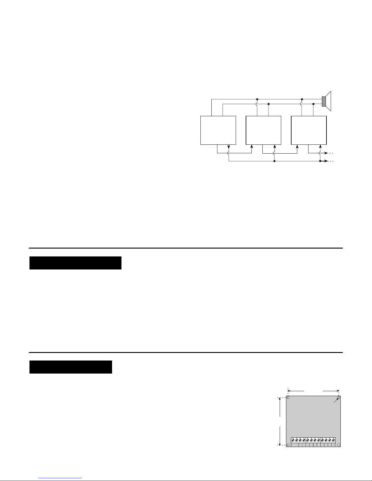
down. Hi-Fi amplifiers and CD players have a fixed level LINE
output that would normally overload the EXT. input of the SP-5A. A
simple attenuator is therefore required (Fig. 9).
When using the attenuator, turn the 1 kΩpotentiometer all the way
down, make an experimental recording (see Steps A through D
below) and play it back (as explained in para. 4.3). If the recording
level is too low, turn the potentiometer slightly up and make another
recording. Continue like this until you are satisfied with the results.
47
1k
EXT. INPUT
OF SP-5A
LINE OUT
GROUND
HI-FI AMPLIFIER
OR CD PLAYER
(1.4 – 5.6 Vp-p
ACROSS 10 ký)
10 k
Figure 9. Line Output Attenuator
Whatever the recording source, proceed as follows:
A. Prevent the 4 channel inputs from being accidentally triggered
into playback.
B. Select the recording mode by setting lever No. 1 of
the Function Control DIP switches to ON.
C. Select the 1st audio channel by setting lever No. 1of the
"CHANNELS" selector to ON (verify that all other levers of this
switch are OFF).
Note: Time your recording carefully so as to leave memory
space for all other message segments you intend to record.
Recordings shorter than 0.5 s will not be saved.
D. Depress and hold down the REC button. The on-board LED
will light. Start speaking immediately. The recording stops and
the LED goes out once you release the REC button.
Note: The LED may flash rapidly, indicating that the new
recording exceeds the time allocated to channel 1 by the
previous "memory partition table". Cancel the previous
memory partition table by erasing all previous recordings
(para. 4.1). Rapid flashing may also indicate total recording
timeout (see Step H below).
E. Set lever No. 1of the "CHANNELS" selector to OFF and select
the next channel by setting its respective switch lever to ON.
F. Record as in Step D above. Continue like this until you finish
with the 4th channel.
G. Set all 4 levers of the "CHANNELS" selector to ON.
H. Record the common message as in Step D above. If an alert
tone is desired as an attention signal before or after the voice
message, you could record a few seconds of a running siren
as the common message. The siren speaker should be
placed face down on a flat surface 30 to 60 cm (1 to 2 ft) from
the SP-5A. Adjust the distance between the siren and the SP-
5A as needed until the desired sound quality is achieved.
Important! If the overall time limit is exceeded, the LED will
flash rapidly. Erase all previous recordings (Para. 4.1), rephrase
your messages to make them shorter and record again. Save
time by not pausing after pressing the REC button.
I. Return all channel switches to OFF.
J. In a multi-unit installation repeat the entire recording
procedure for each unit.
4.3 Testing by Playback
A. Verify that the non-repeating playback mode is selected
(Para. 1.3C).
B. Select PLAY by setting lever No. 1of the Function Control
DIP switches to OFF (Para. 1.3B).
C. Set lever No. 2 of the Function Control DIP switches to the
desired playback order (Para. 1.3B).
D. Select the first audio channel by setting lever No. 1of the
"CHANNELS" DIP switch selector to ON or by triggering input
CH1. The common message will be heard over the loud-
speaker, followed by the channel's individual message. Adjust
the VOL (volume) control for the desired sound level.
E. Set lever No. 1of the "CHANNELS" selector to OFF.Select
the second audio channel by setting lever No. 2 to ON or by
triggering input CH2. Listen to the playback.
F. Test Channels 3 and 4 in a similar manner and return all
channel switches to OFF.
G. In a multi-unit installation, repeat the entire testing procedure
for each unit.
If all messages are coherent, the recording operation has been
concluded successfully.
WARRANTY
WARRANTYWARRANTY
WARRANTY
Visonic Ltd. and/or its subsidiaries and its affiliates ("the Manufacturer") warrants its
products hereinafter referred to as "the Product" or "Products" to be in conformance with
its own plans and specifications and to be free of defects in materials and workmanship
under normal use and service for a period of twelve months from the date of shipment by
the Manufacturer. The Manufacturer's obligations shall be limited within the warranty
period, at its option, to repair or replace the product or any part thereof. The Manufacturer
shall not be responsible for dismantling and/or reinstallation charges. To exercise the
warranty the product must be returned to the Manufacturer freight prepaid and insured.
This warranty does not apply in the following cases: improper installation, misuse,
failure to follow installation and operating instructions, alteration, abuse, accident or
tampering, and repair by anyone other than the Manufacturer.
This warranty is exclusive and expressly in lieu of all other warranties, obligations or
liabilities, whether written, oral, express or implied, including any warranty of
merchantability or fitness for a particular purpose, or otherwise. In no case shall the
Manufacturer be liable to anyone for any consequential or incidental damages for breach
of this warranty or any other warranties whatsoever, as aforesaid.
This warranty shall not be modified, varied or extended, and the Manufacturer does not
authorize any person to act on its behalf in the modification, variation or extension of this
warranty. This warranty shall apply to the Product only. All products, accessories or
attachments of others used in conjunction with the Product, including batteries, shall be
covered solely by their own warranty, if any. The Manufacturer shall not be liable for any
damage or loss whatsoever, whether directly, indirectly, incidentally, consequentially or
otherwise, caused by the malfunction of the Product due to products, accessories, or
attachments of others, including batteries, used in conjunction with the Products.
The Manufacturer does not represent that its Product may not be compromised and/or
circumvented, or that the Product will prevent any death, personal and/or bodily injury
and/or damage to property resulting from burglary, robbery, fire or otherwise, or that the
Product will in all cases provide adequate warning or protection. User understands that a
properly installed and maintained alarm may only reduce the risk of events such as
burglary, robbery, and fire without warning, but it is not insurance or a guarantee that
such will not occur or that there will be no death, personal damage and/or damage to
property as a result.
The Manufacturer shall have no liability for any death, personal and/or bodily injury
and/or damage to property or other loss whether direct, indirect, incidental,
consequential or otherwise, based on a claim that the Product failed to function.
However, if the Manufacturer is held liable, whether directly or indirectly, for any loss or
damage arising under this limited warranty or otherwise, regardless of cause or origin, the
Manufacturer's maximum liability shall not in any case exceed the purchase price of the
Product, which shall be fixed as liquidated damages and not as a penalty, and shall be
the complete and exclusive remedy against the Manufacturer.
Warning: The user should follow the installation and operation instructions and among
other things test the Product and the whole system at least once a week. For various
reasons, including, but not limited to, changes in environmental conditions, electric or
electronic disruptions and tampering, the Product may not perform as expected. The user
is advised to take all necessary precautions for his /her safety and the protection of
his/her property.
6/91
VISONIC LTD. (ISRAEL): P.O.B 22020 TEL-AVIV 61220 ISRAEL. PHONE: (972-3) 645-6789, FAX: (972-3) 645-6788
VISONIC INC. (U.S.A.): 10 NORTHWOOD DRIVE, BLOOMFIELD CT. 06002-1911. PHONE: (860) 243-0833, (800) 223-0020 FAX: (860) 242-8094
VISONIC LTD. (UK): FRASER ROAD, PRIORY BUSINESS PARK, BEDFORD MK44 3WH. PHONE: (0870) 7300800 FAX: (0870) 7300801
INTERNET: www.visonic.com
VISONIC LTD. 2003 SP-5A DE6113- (REV. 2 ,5/03)
Table of contents
Other Visonic Recording Equipment manuals