2 DE4044 MCX-600 Installation Instructions
At all levels except for level 0, messages are retained in the
repeater's memory until taken care of by the next repeater.
B. Selecting Level Tags
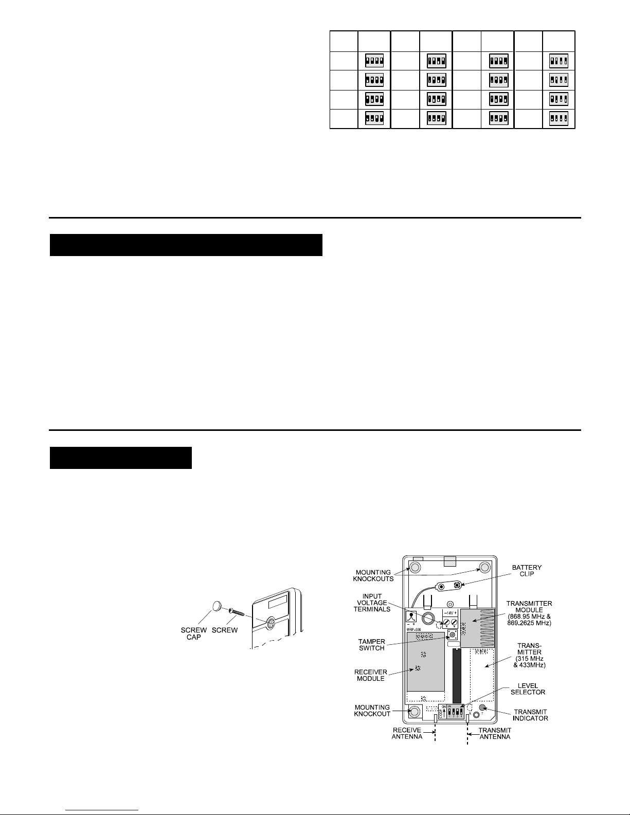
The 4-position DIP switch on the repeater's PCB allows the
installer to select the desired level by setting its 4 switch levers to
16 different combinations, as shown in Figure 3.
All repeaters leave the factory with the 4 level selection switches
set to OFF (Level 0 is selected).
3.4 Service Messages
Three kinds of event codes are automatically included in a
service transmission in addition to the repeater’s own 24-bit ID:
•Power Failure/Low Battery •Tamper •Hourly test report.
The power failure/low battery message is transmitted 30 minutes
after loss of power (AC or DC) at the voltage input terminals. Upon
power failure, recharging stops and the backup battery takes over.
It is therefore correct to assume that without power input, the
battery is gradually weakening and may be reported as “low”.
Switch
Settings
LEVEL
LEVEL 1
LEVEL 2
LEVEL 3
LEVEL 4
LEVEL 5
LEVEL 6
LEVEL 7
LEVEL 0
Switch
Settings
LEVEL Switch
Settings
L EV EL Switch
Settings
L EV EL
4321
ON
4321
ON
4321
ON
4321
ON
LEVEL 9
LEVEL 10
LEVEL 11
LEVEL 8 LEVEL 12
LEVEL 13
LEVEL 14
LEVEL 15
4321
O N
4321
O N
4321
O N
4321
O N
4321
O N
4321
O N
4321
O N
4321
O N
4321
ON
4321
ON
4321
ON
4321
ON
Figure 3. Selecting Level Numbers
Power / battery restore is reported only in the following test report.
Tamper restore is reported immediately upon occurrence.
If the tamper or power failure condition persists long enough,
the respective alerts will be sent out again with each test report.
The repeater ID in the outgoing service message identifies the
message origin (the specific repeater) to the receiver. Service
personnel will therefore know exactly where the problem lies.
4. THE COMMUNICATION PROCESS
4. THE COMMUNICATION PROCESS4. THE COMMUNICATION PROCESS
4. THE COMMUNICATION PROCESS
Once the repeater is powered up, its receiver section stands by for
incoming messages, whereas its transmitter section is inactive.
A. Repeaters at any level collect and save messages received
from transmitters deployed in their respective coverage areas
and also from repeaters in higher levels. Messages are rejected
if they do not include the proper 24-bit ID format and/or do not
pass the checksum test.
B. Valid messages are saved in the message buffer, for
retransmission as soon as transmission is allowed.
Note: Before retransmission, the repeater checks whether the
RF channel is free - it is programmed to transmit on a free
channel only. However, in case of continuous interference or
uninterrupted stream of incoming messages, a 3-second time-
out will cause the repeater to stop receiving, retransmit the
contents of its message buffer and revert to the receive mode.
C. Once transmission is allowed, the repeater retransmits all
messages stored in its buffer, "first in, first out".
Note: To prevent collision of messages transmitted by repeaters
at various levels, a different REPEAT INTERVAL (inter-message
interval) is programmed for each level. This interval is
determined automatically as a function of the repeater's LEVEL.
D. Upon retransmission, messages are picked up by the target
receiver (if the system includes only a single repeater) or by a
lower level repeater for further transmission towards the target
receiver.
E. If a repeater (Level 1 and up) receives a message transmitted
by a lower level repeater and identifies it as one it had already
retransmitted, it will stop repeating the message and will delete
the message from its buffer.
F. Without acknowledgement from a lower level repeater, the
higher level repeater will transmit the message again after the
"repeat interval" (which depends on the repeater's level). A
maximum of 8 repetitions is allowed before the repeater "gives
up" and passes on to the next message.
5. INSTALLATION
5. INSTALLATION5. INSTALLATION
5. INSTALLATION
5.1 Repeater's Locatio Selectio
A. In a single repeater setup, install the repeater where good
communication is assured with the target receiver and with
the transmitters deployed in the repeater's coverage area. In
multi-repeater networks, good communication must be assured
with the deployed transmitters and the repeaters at the next
higher and next lower levels.
B. Do not stretch the coverage area to its utmost limit, because
this can disrupt your communication link. It is better to add
repeaters than to rely on marginal reception.
C. Mount the repeater as high
as possible above the floor
and well away from metal
chimneys, large metal
cabinets, metal doors and
reinforced concrete walls,
all of which may reduce the
communication range.
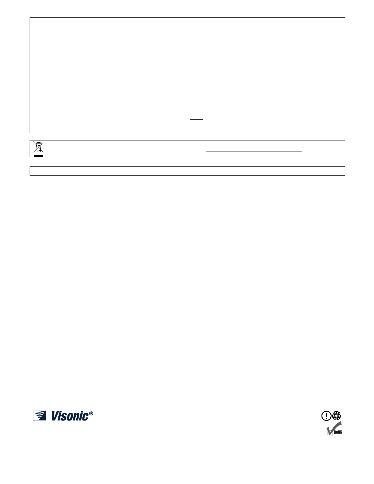
Figure 4. Front cover Assembly
5.2 Mou ti g Procedure
A. Remove the screw and the front cover (see Fig. 4). The round
plastic cap is supplied separately in a small nylon bag.
B. Mount the base (equipped with the printed circuit board) in the
selected location, using the mounting knockouts (see Fig. 5).
C. Make sure the antenna wires hang down vertically (do not
allow them to bend close together). Tape them to the wall if
necessary.
D. Snap the battery clip onto the battery and place the battery in
the vacant space above the P.C. board.
E. Plug the AC adapter into an uninterruptible AC outlet and
connect the low voltage wires to the repeater's 14 V terminals.
Note: Any standard DC power supply or AC step-down
transformer would do, if it delivers 12V AC or DC / 100 mA.
(Refer to Section 2 for input voltage limits.)
Figure 5. MCX-600, Cover Removed