Visslo F8 premier User manual
OPERATION MANUAL
3D PATTERNLESS LENS EDGER/ F8 premier
Rev. 1014-091

WWW.VISSLO.COM
#301, Apollo Town, 18-36, Sanbon-Dong, Gunpo-City, Korea Tel+82 31 349 8693 Fax+82 31 349

1. Introduction
1.1 Product outline & Intended use
1.2 Lens materials and edging modes
1.3 Accessary and locking / unlocking procedure
. System components
2.1 System Layout
2.1.1 Overvie
2.1.2 Front Vie
2.1.3 Rear Vie
2.2 Main Panel
2.3 Edger key s itch
2.3.1 Sub Panel 2 (Right)
2.4 edging unit
3. Edgering data input
3.1 material selection
3.2 Edging data input
3.2.1 Standard lens
3.2.2 Bi-focal lens
4. Edgings
4.1 Standard(Beveling)
4.1.1 Automated edging
4.1.2 Controlled edging ( Decenteriged Edring )
4.2 Optional edging
4.2.1 Classifications by frames
4.2.1.1 Flat (Rimeless) edging
4.2.1.2 Grooving
A) Automated
B) Controlled ( Decenteriged )
4.2.2 Classifications by lens
4.2.2.1 EX lens edging
4.2.3 Edging by the function
4.2.3.1 Frame exchange edging
4.2.3.2 Safe mode lens Edging
4.3 Check and adjust lens size
3D PATTERNLESS LENS EDGER/F8 premier
INDEX

5. Save and retrieve data
5.1 Save and retrieve data
5.1.1 Save data
5.1.2 Retrieve data
5.1.3 Adjust the parameters
6. Installation and maintenance
6,1 Installation
6,2 check
6,3 maintenance
6,4 cleaning
7. Safety
7.1 Caution hile use
7.2 Transfer
7.3 Wiring
8. Error codes
9. Usable environmental conditions
10. Symbol Description

1.1 Outline of the Product & Intended use
The lens Edger ( Model:F8 premier ) is edging the optical lens according to the tracing
data hich is imported from the tracer unit ( Moder st-88 )
Thelens edger ( Moder:F8 premier ) consists of Edger unit, display and electronic unit.
The lens edger ( Model: F8 premier ) can be equipped ith OMA compliances for
laboratory operation
1. Lens materials and edging modes
x : Edging is not available
Flat
Bevel
Lens
material
(Acrylic resin)
Edging mode
(Hi-index plastic)
PLA
(Plastic)
HPA
oo
Beveling
o
o
o
PolishingGrooving Flat Chamfering
o
o
o o
PC
(Polycarbonate)
GLS
(glass)
o
o o
o
o
o
o
ACR
o
o
o
o
o
o o
x
o
Chapter 1. Introduction
o
x x
o o
1.3 Accessaries &locking & unlocking procedure
1.3.1 Composition
1) Main body 1 Unit
2) Manual blocker 1 Unit ( Optional )
3) Po er cable
4) Leap tape -- 100 pcs for 28mm, 100 pcs for 18mm
5) Operation manual
6) Dressing stick -- #100, #400, #3000 each 1 pc
#100 -- Glass heel
#400 -- Finishing heel , Chamfering heel
#3000 -- Polishing heel
7) Tool Box
8) Pump Unit (Optional)
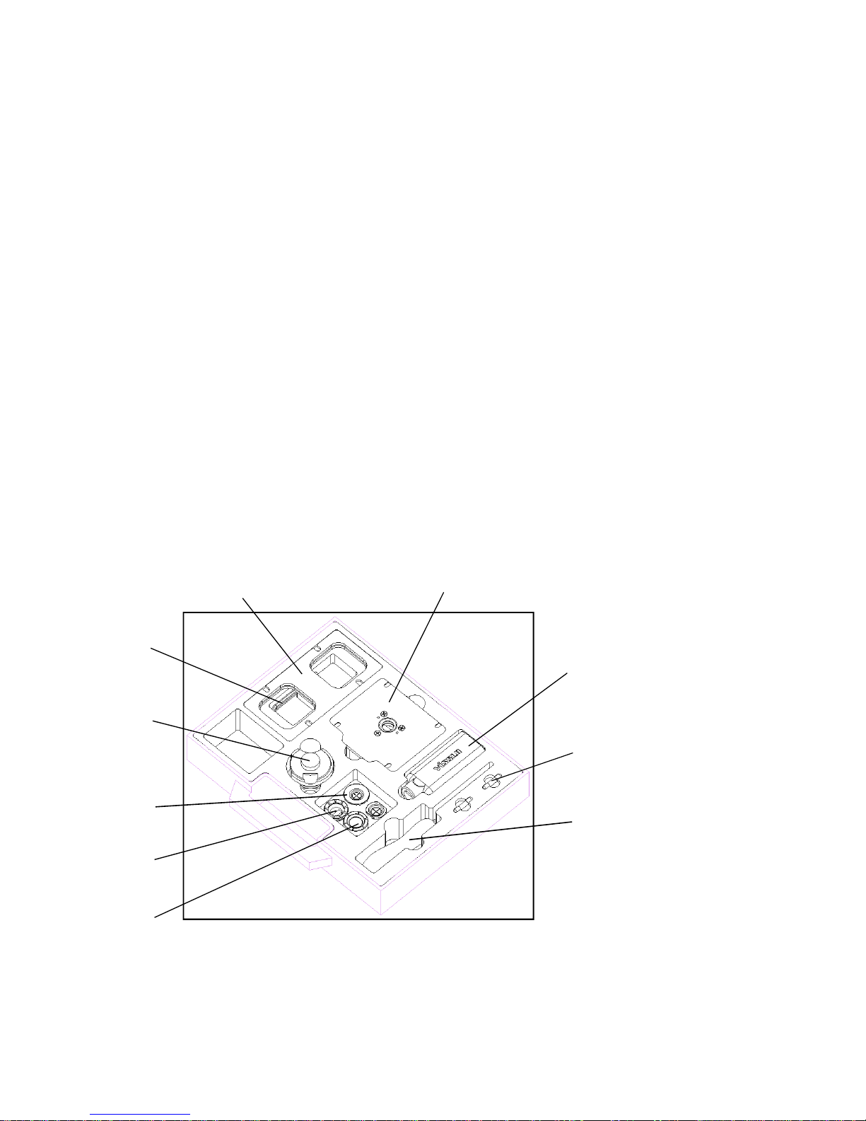
Tool Box Composition
Frame jig
Wrench set
Calibration jig
Leap cup
Lens adaptor
Lens clamp
Fuse
Leap cup remover
( Block remover )
Pattern & Demo Lens Holder
Wrench driver
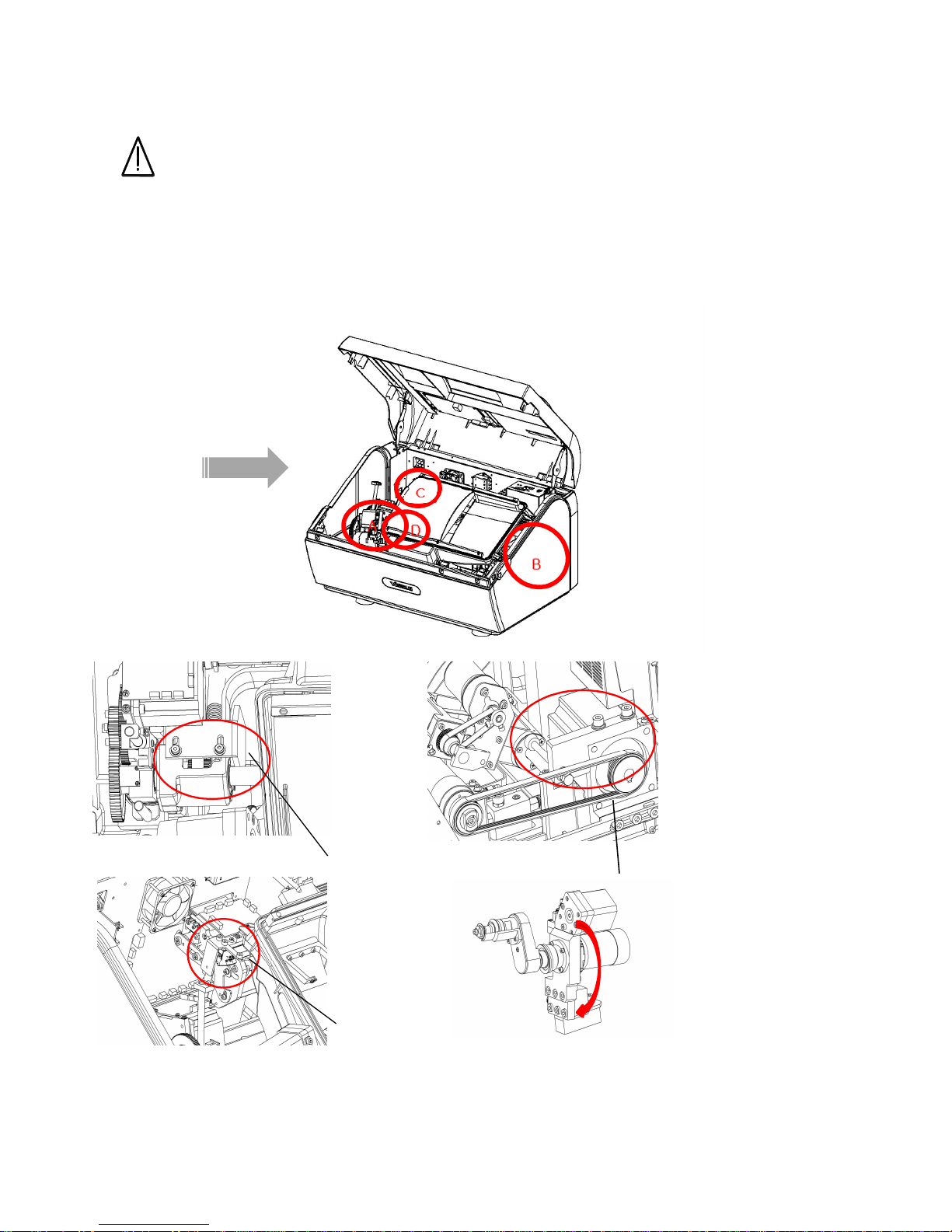
1.3. Accessaries and Locking & unlocking procedure
Warning
Be sure to take fixing unit out before turning on certainly since fixing unit are
installed to prevent the damage during transportation
1) Open cover upside after taking the bolts out both sides of the cover upside
fixing unit A
fixing unit Afixing unit A
fixing unit A~
~~
~D
DD
D
red-colored
red-coloredred-colored
red-colored red-colored
Head Up
Head UpHead Up
Head Up/
//
/Down Locking A
Down Locking ADown Locking A
Down Locking A
red-colored
Head L
Head LHead L
Head L-
--
-R Locking B
R Locking BR Locking B
R Locking B
Edger fixing unit location
Edger fixing unit locationEdger fixing unit location
Edger fixing unit location
Feeler Locking C
Feeler Locking CFeeler Locking C
Feeler Locking C Groove Locking
Groove LockingGroove Locking
Groove Locking D
DD
D
fixing with
fixing with fixing with
fixing with
adhesive tape
adhesive tapeadhesive tape
adhesive tape
*chock any interference with movement
*chock any interference with movement*chock any interference with movement
*chock any interference with movement
Locking units should always removed with turn off condition.
Locking units should always removed with turn off condition.Locking units should always removed with turn off condition.
Locking units should always removed with turn off condition.
locking units should always be placed when the transportation is necessary.
locking units should always be placed when the transportation is necessary.locking units should always be placed when the transportation is necessary.
locking units should always be placed when the transportation is necessary.
improper handling could cause the damage which is not covered underwarrenty.
improper handling could cause the damage which is not covered underwarrenty.improper handling could cause the damage which is not covered underwarrenty.
improper handling could cause the damage which is not covered underwarrenty.
3)Edger fixing lockerA ,B, C, D is limited.
3)Edger fixing lockerA ,B, C, D is limited.3)Edger fixing lockerA ,B, C, D is limited.
3)Edger fixing lockerA ,B, C, D is limited.
.1 System Layout
.1.1 System Overview
Fig. 1
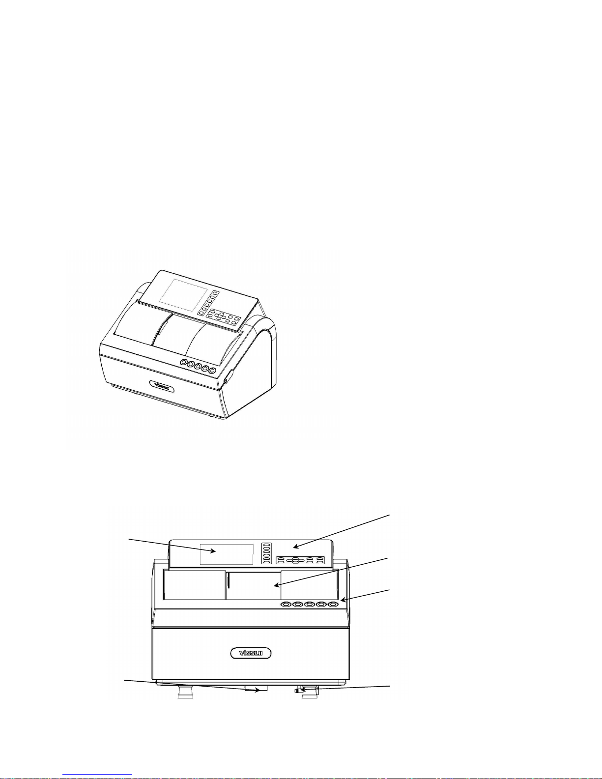
.1. Front view
Chapter . System components
WxLxH (Approx.) : 800 x 430 x 410 (mm)
Control
ControlControl
Control Panel
PanelPanel
Panel
Sliding Cover
Sliding CoverSliding Cover
Sliding Cover
Edger Key Switch
Edger Key SwitchEdger Key Switch
Edger Key Switch
Water Drain Port
Water Drain PortWater Drain Port
Water Drain Port
Water Inlet Port
Water Inlet PortWater Inlet Port
Water Inlet Port
LCD Display
LCD DisplayLCD Display
LCD Display

* Control Panel : Sho s and control all menu
* Edger Key s itch : Controls conditions before edging
* Sliding Cover : Shields the noise and filthy ater hile edging
* Water Inlet Port : Outside nozzle to deliver ater hile edging
* Water Drain Port : Outlet to release ater after edging
.1.3 Rear view
Fig. 3
* RS- 3 C Connector : Connector to interface ith equipment outside.
* Barcode Scanner Connector : Connector to interface ith bar code scanner
Cooling Fan
Cooling FanCooling Fan
Cooling Fan
RS
RSRS
RS-
--
-232
232232
232C
C C
C
Interface Connector
Interface ConnectorInterface Connector
Interface Connector
Barcode
BarcodeBarcode
Barcode
Scanner Connector
Scanner ConnectorScanner Connector
Scanner Connector
Pump
PumpPump
Pump1
1 1
1 Connector
ConnectorConnector
Connector
Power Switch
Power SwitchPower Switch
Power Switch
Power Connector
Power ConnectorPower Connector
Power Connector
Blocker
BlockerBlocker
Blocker
Connector
ConnectorConnector
Connector
Tracer
TracerTracer
Tracer
Connector
ConnectorConnector
Connector

. Control Panel
Fig. 4
1. : Lens material --- Choose PLA(Plastic), HPL(High index plastic),
PC(Polycarbonate),GLS(Glass),or ACR(Acrylic resin)
2. : Frame material --- Choose MTL(Metal), CEL(Celluloid)/ZYL, PNT(t o-point),
or NYL(Nylor)
3. : Edging mode - 3:7(Auto), 4:6(Auto), 5:5(Auto), CTR(Manual),
EX(EX lens ) are available.
EX lens edging
Controlled grooving
Automated grooving
Rimless(Flat)edging
Edging mode
Controlled beveling
Automated beveling
12114 6 7 8 910
251 3
Table of contents


