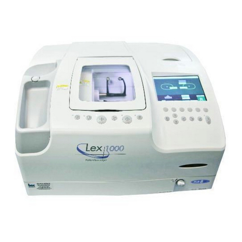
Nidek Medical Le 1000 User manual

PATTERNLESS EDGER
Model
SERVICE MANUAL
June 2008
Pages in total: 152
LLE14BRDA001A/E

NIDEK CO., LTD. : 34-14, Maehama, Hiroishi-cho, Gamagori, Aichi 443-0038, Japan
(Manufacturer) Telephone: 81-533-67-6611
Facsimile: 81-533-67-6610
NIDEK CO., LTD : 3F Sumitomo Fudosan Hongo Bldg., 3-22-5, Hongo,
(Tokyo Office) Bunkyo-Ku, Tokyo 113-0033, Japan
Telephone: 81-3-5844-2641
Facsimile: 81-3-5844-2642
NIDEK INCORPORATED : 47651 Westinghouse Drive, Fremont, California 94539, U. S. A.
(United States Agent) Telephone: 1-510-226-5700
Facsimile: 1-510-226-5750
NIDEK SOCIETE ANONYME : Europarc 13, rue Auguste Perret, 94042 CRETEIL, France
(EU Authorized Representative) Telephone: 33-1-49 80 97 97
Facsimile: 33-1-49 80 32 08

I
Table of Contents
§ 1 INTRODUCTION ..............................................................................1-1
§ 2 SAFETY PRECAUTIONS.................................................................2-1
§ 3 PRODUCT OUTLINE .......................................................................3-1
3.1 Quality Standard .................................................................................................... 3-1
3.2 Configuration .......................................................................................................... 3-3
3.3 Model Configuration ............................................................................................... 3-9
3.4 Wheel Configuration ............................................................................................ 3-10
3.5 Labels ....................................................................................................................3-11
3.6 ASSY. Layout ....................................................................................................... 3-13
3.7 Electrical Component Layout ............................................................................... 3-14
3.8 Replacement Part List.......................................................................................... 3-17
§ 4 TROUBLESHOOTING ....................................................................4-1
§ 5 REMOVING PROCEDURES ............................................................5-1
5.1 Prior to Removal Work ........................................................................................... 5-1
5.2 Abbreviations for Screws ....................................................................................... 5-1
5.3 Opening Top Cover ASSY. ..................................................................................... 5-2
5.4 Removing Covers ................................................................................................... 5-2
§ 6 REPLACEMENT PROCEDURES ....................................................6-1
6.1 Rocker Switch (80460-00123) ............................................................................... 6-1
6.2 Main Board (44401-BA01) ..................................................................................... 6-1
6.3 Inverter (80607-00027) .......................................................................................... 6-2
6.4 Monochrome LCD (80607-00025) ......................................................................... 6-2
6.5 Trace SW Board (44001-BA02) ............................................................................. 6-3
6.6 Setting SW Board (44401-BA03) .......................................................................... 6-3
6.7 Main SW Board (44401-BA04) .............................................................................. 6-4
6.8 Cover Relay Board (44401-BA07) ......................................................................... 6-5
6.9 Sensor Cable (44401-CA37) ................................................................................. 6-5
6.10 Wheels ................................................................................................................. 6-6
6.11 Grooving Wheel and Safety Bevel Finishing Wheel ........................................... 6-8
6.12 Stylus (40340-M474) ............................................................................................ 6-8
6.13 Tracing unit ASSY. (43401-4000) ........................................................................ 6-9
6.14 Feelers ............................................................................................................... 6-10
6.15 Feeler ASSY. (40340-4100) ................................................................................6-11
6.16 Lens Measurement Unit ASSY. (44401-4000) .................................................. 6-12
6.17 Lens Measurement Board (40340-BA06) ......................................................... 6-12

II
6.18 Pulse Motor (40340-E033) ................................................................................. 6-13
6.19 Encoder (40340-E043) ...................................................................................... 6-13
6.20 Cables (40340-CA31, CA32, CA33) .................................................................. 6-13
6.21 Safety Beveling/Grooving ASSY. (44001-6000) ................................................ 6-14
6.22 Spindle ASSY. (44001-6600) ............................................................................. 6-15
6.23 Pulse Motor (40340-E035) ................................................................................. 6-15
6.24 Sensor Cable (44001-CA42) ............................................................................. 6-15
6.25 Brushless Motor (40347-E054) .......................................................................... 6-16
6.26 Guide (44401-M931) .......................................................................................... 6-17
6.27 Processing Chamber ASSY. (44401-9300) ....................................................... 6-17
6.28 Lower Processing Chamber ASSY. (44001-9100) ............................................ 6-18
6.29 Carriage ASSY. (44401-5000) ........................................................................... 6-19
6.30 Chuck Axis Motor ASSY. (44001-5300) ............................................................. 6-19
6.30.1 Y axis motor ASSY. (44001-5400) ............................................................ 6-20
6.30.2 Y axis stepping motor (44001-E035) ....................................................... 6-20
6.31 DC Motor (44001-E042)..................................................................................... 6-21
6.32 θAxis Stepping Motor (44401-E022) ................................................................. 6-21
6.33 Carriage Relay Board (44401-BA05) ................................................................ 6-22
6.34 Sensor Cables (44001-CA27, CA29) ................................................................ 6-22
6.35 Sensor Cables (44001-CA26, CA28) ................................................................ 6-22
6.35.1 X axis motor ASSY. (44001-1100) ............................................................ 6-23
6.35.2 Pulse motor (44001-E037), Sensor cable (44001-CA17) ....................... 6-23
6.36 Feedwater ASSY. (44001-1600) ........................................................................ 6-24
6.37 Lid ASSY. (44401-2200) .................................................................................... 6-24
6.38 DC Fan (40350-E016)........................................................................................ 6-25
6.39 Communication Connector Board (44401-BA08) ............................................. 6-25
6.40 Cables CA07 (44001-CA07) .............................................................................. 6-25
6.41 Fuse Holder (80401-00038) .............................................................................. 6-26
6.42 Inlet (80457-00085) ........................................................................................... 6-26
6.43 Reactor (40350-E043) ....................................................................................... 6-27
6.44 Regenerative Resistor for BL Motor (40340-E069) ........................................... 6-27
6.45 Mains Part ASSY. (44401-1200, 12A0) ............................................................. 6-28
6.46 Inverter for BL Motor (40340-E066, E067) ........................................................ 6-28
6.47 Switching Regulator (80602-00107) .................................................................. 6-29
6.48 Motor Driver (44001-E036) ................................................................................ 6-29
6.49 SSR Board (44001-BA09) ................................................................................. 6-29
6.50 Line Noise Filter (80404-00043) ........................................................................ 6-30
§ 7 SETTING/ADJUSTMENT .................................................................7-1
7.1 Notes for Proper Settings and Adjustments .......................................................... 7-1
7.2 Utility Program ........................................................................................................ 7-2
7.2.1 Writing program to Master CPU ................................................................... 7-2
7.2.2 EEPROM initialization .................................................................................. 7-3
7.2.3 Writing program to tracing unit CPU ............................................................ 7-4
7.2.4 Parameter settings ....................................................................................... 7-5
7.2.4.1 Displaying PARAMETER SETTING screen ........................................ 7-5
7.2.4.2 Displaying WHEEL PARAMETER screen .......................................... 7-6
7.2.4.3 Parameter list ...................................................................................... 7-7
7.2.5 HARDWARE TEST program ...................................................................... 7-10

III
7.3 Mechanical Components ..................................................................................... 7-13
7.3.1 Carriage ASSY. (44401-5000) .................................................................... 7-13
7.3.1.1 Rattle removal of carriage ASSY. bearing ........................................ 7-13
7.3.1.2 Engagement of X axis motor ASSY. motor gear .............................. 7-14
7.3.1.3 Height of carriage ASSY. Y axis ........................................................ 7-15
7.3.1.4 θaxis of carriage ASSY. Y axis ......................................................... 7-16
7.3.1.5 Position of carriage ASSY. left/right shaft ......................................... 7-17
7.3.2 Lens measurement unit ASSY.................................................................... 7-18
7.3.2.1 Feeler ASSY. height .......................................................................... 7-18
7.3.2.2 Initial position of feeler ASSY. ........................................................... 7-19
7.3.2.3 Voltage of lens measurement unit ASSY. ......................................... 7-19
7.3.3 Safety beveling/grooving ASSY. (44001-6000) ......................................... 7-21
7.3.3.1 Position of safety beveling/grooving ASSY. arm .............................. 7-21
7.3.4 Chuck pressure .......................................................................................... 7-22
7.3.4.1 Tentative chuck pressure .................................................................. 7-22
7.3.4.2 Chuck pressure ................................................................................. 7-23
7.3.5 Tracing unit (43401-4000) .......................................................................... 7-24
7.3.5.1 Tilt of tracing unit stylus ..................................................................... 7-24
7.3.5.2 Position of cable CA63...................................................................... 7-24
7.3.5.3 Cleaning of pattern tracing pin .......................................................... 7-25
7.4 Electrical Components ......................................................................................... 7-26
7.4.1 Parameters BL motor inverter .................................................................... 7-26
7.4.2 Parameter list of BL motor (40340-E066, E067) inverter .......................... 7-27
7.4.3 Trip table of BL motor inverter .................................................................... 7-30
7.5 Calibration ............................................................................................................ 7-31
7.5.1 Displaying calibration screen ..................................................................... 7-31
7.5.2 Attaching calibration jig............................................................................... 7-31
7.5.3 Calibration of safety beveling/grooving ASSY. .......................................... 7-32
7.5.4 Wheel calibration ........................................................................................ 7-33
7.5.5 Calibration of lens measurement unit ASSY. ............................................. 7-34
7.5.6 Torque calibration of tracing unit ................................................................ 7-35
7.5.7 Frame auto calibration of tracing unit ........................................................ 7-35
7.5.8 Pattern auto calibration of tracing unit ....................................................... 7-35
7.5.9 Full calibration of tracing unit ..................................................................... 7-36
7.6 Processing Adjustment ........................................................................................ 7-38
7.6.1 Feeler axis .................................................................................................. 7-38
7.6.2 Finish size ................................................................................................... 7-41
7.6.3 Bevel position ............................................................................................. 7-41
7.6.4 Lens axis..................................................................................................... 7-42
7.6.5 Polish (differential, polishing wheel height, bevel, axis) ............................ 7-44
7.6.5.1 Polish (differential, polishing wheel height) ...................................... 7-44
7.6.5.2 Bevel position to be polished ............................................................ 7-45
7.6.5.3 Flat polish axis................................................................................... 7-47
7.6.5.4 Bevel polish axis ............................................................................... 7-48
7.6.5.5 Polycarbonate polish differential....................................................... 7-49
7.6.5.6 Polish size ......................................................................................... 7-49
7.6.6 Groove ........................................................................................................ 7-50
7.6.6.1 Groove depth .................................................................................... 7-50
7.6.6.2 Groove position ................................................................................. 7-51

IV
7.6.6.3 Groove axis ....................................................................................... 7-52
7.6.7 Safety bevel ................................................................................................ 7-53
7.6.8 Bevel/safety bevel axis ............................................................................... 7-54
7.6.9 Flat edge/safety bevel axis ........................................................................ 7-55
7.7 Other Settings and Adjustments .......................................................................... 7-57
7.7.1 Dressing wheels ......................................................................................... 7-57
§ 8 SUPPLEMENT .................................................................................8-1
8.1 Wiring Diagram ...................................................................................................... 8-1
8.2 Connector Cable .................................................................................................... 8-2
8.3 Main Board (44401-BA01) ..................................................................................... 8-7
8.4 Grease .................................................................................................................... 8-8
8.5 Grease MSDS ...................................................................................................... 8-10
8.5.1 NIPPECO LLP ............................................................................................ 8-10
8.5.2 BE-4 ............................................................................................................ 8-12
8.5.3 SHV-2.......................................................................................................... 8-14
8.5.4 NBU15 ........................................................................................................ 8-16
8.6 Troubles and Measures ....................................................................................... 8-21
8.7 Jigs ....................................................................................................................... 8-26
8.8 Tools ..................................................................................................................... 8-27
8.9 Consumables ....................................................................................................... 8-27

LLE14BRDA001A/E
1 - 1
• This Service Manual is for the NIDEK PATTERNLESS EDGER, Le 1000.
• For correct service, thorough understanding of the contents of this manual is required
prior to the service.
• This manual mainly describes simple remedies such as part replacement.
• Disassembly or repair must be performed by NIDEK service persons or other qualified
personnel.
• Refer to the Operator’s Manual, Parts List, and Installation Manual for the Le 1000.
• Refer to the Service Manual Annex for important changes.
• In case the system cannot be repaired according to the procedures described in this
service manual, please report the serial number of the system, version of the software,
and details of the symptom or symptoms.
§
1 INTRODUCTION

[This page is intentionally left blank.]
LLE14BRDA001A/E
1 - 2

LLE14BRDA001A/E
2 - 1
§
2 SAFETY PRECAUTIONS
<General precautions>
• Maintenace must be performed by NIDEK service persons or other qualified personnel.
• Perform all maintenance according to the procedures described in this manual.
Failure to do so may cause unexpected accident or malfunction.
• When moving the system, use two or more persons. You may hurt your back or may fall
down if you carry it alone.
• When performing maintenance, turn off the power switch and disconnect the power cord
from the wall outlet unless the power needs to be on.
• Never wipe the covers using an organic solvent such as a paint thinner. Doing so may ruin
the surface and damage the appearance of the system.
<Maintenance precautions>
• In case of system malfunction, check the symptom and turn off the power .
• Do not drop parts or screws inside the system, nor bump it against surrounding objects.
• Prepare storage cases so as not to lose the removed parts or screws.
• Tighten or loosen screws with proper tools.
• After loosening the screws fixed by a threadlocking adhesive, be sure to reapply the
threadlocking adhesive to the screws when retightening them.
• After replacing parts, confirm that they are fixed in their original positions securely before
turning on the power.
• Should you observe smoke or strange odors being issued from the system, immediately turn
off the power switch, disconnect the power cord from the outlet, and investigate the cause.
If the system is powered in abnormal conditions, fire, electric shock, or total loss of the
system may result.
• See Wiring Diagram and Connecting Cable to check cable breaks as described in
“TROUBLESHOOTING”. In addition, check cables for the following:
1. Connectors are connected and crimped securely.
2. No contact failure occurs after re-connection of connectors.
3. Cables are soldered properly.
Do not yank the cables with excessive force. Doing so could cause cable breakage.
• Do not perform servicing with wet hands. Doing so could cause electric shock or malfunction.
• Prevent water seepage into the system.
• Do not apply excessive force to the stylus of the tracing unit. Doing so could cause deformation
or malfunction of the stylus.
• Make a lens material selection correctly according to the lens to be processed. If an improper
material is selected, the lens may break or the lifetime of processing wheels may be shortened
substantially.
• Never open the processing chamber door while the wheel is rotating. Spray containing
processing waste may come into your eyes.
• Keep hands and face away from the rotating wheel.
• Replace the wheel with gloves on after cleaning the wheel and inside of the processing
chamber. Bare hands can be hurt by glass-processing waste.
• Safety bevel the front and rear surfaces of glass lenses after processing. Subtle burrs may
damage your skin.
• Never use the adjustment jigs for purposes other than those intended.

[This page is intentionally left blank.]
LLE14BRDA001A/E
2 - 2

3 - 1
LLE14BRDA001A/E
3.1 Quality Standard
Accessories
㧦44401-0022 (Refer to the Le 1000 Parts List㧕
㧦44401-0032
㧦44401-0042
Item Acceptance criteria Measurement method/tool
Classi-
fication
Configuration
Appearance
Function
Operation
Processing performance
Main body :
1 unit
Visually check the
contents and numbers.
Visually check the
contents and numbers.
Standard
configuration
Packaging unit
1 per 1 product unit
Gap in cover
juncture
Gap in juncture between covers is ±1.2 mm or less and level
difference is 1 mm or less.
Visual check
Measure if necessary.
(Scale)
Cooling water
volume adjustment
The volume of water can be adjusted by turning the flow control.
Interface
Data can be transmitted and received between a PC and the system.
Data can be transmitted and received between the system and
connected blocker (Ice 1000, ICE-9000, ICE mini).
Connect a PC and
a blocker to check data
transmission/reception.
Visually check the
volume of water.
Mechanical
operation
The processing chamber door and tracing unit lid are smoothly
opened and closed.
Tactile check
Use a stopwatch to time
from when the feelers
go down until when they
come out.
Use a stopwatch to time
from when the tracing
start button is pressed
until when a beep
sounds to indicate
tracing completion.
Tracing speed:
Frame tracing takes 30 seconds or less (both-eye tracing).
Pattern tracing takes 20 seconds or less.
Lens shape measurement takes 15 seconds or less,
or 25 seconds or less when safety beveling is set.
Water leakage from
processing chamber No water leaks from the juncture of the processing chamber door.
Visual check
Processing
performance
Maximum lens size: φ 85 mm or less (within the range of φ 110 mm)
Minimum lens size (horizontal x vertical)
Without safety beveling With safety beveling
Pliable cup
Mini cup
Flat edging Flat edging
Beveling Beveling
φ
φ
Ɋ
Ɋ
Ɋ
Ɋ
ɊɊ
Ɋ
Ɋ
φ
φ
φ
φ
φ
φ
According to the Le 1000
processing accuracy
data (LLE14ARTA001)
§3 PRODUCT OUTLINE

LLE14BRDA001A/E
3 - 2
Processing
accuracy
Processing performance
Item Acceptance criteria Measurement method/tool
Classi-
fication
• Size accuracy
Beveling
Call up φ45 internal data and bevel a CR-39 lens in the Auto
processing mode. The diameter is within φ45 ±0.1 mm.
• Axis
Call up غ45 internal data and bevel a glass/CR-39/polycarbonate
lens in the Auto processing mode. The axis is within ±1°.
Flat edging
• Size accuracy
Call up φ45 internal data and flat-edge a CR-39 lens.
The diameter is within φ45 ±0.1 mm.
• Axis
Call up غ45 internal data and flat-edge a glass/CR-39/poly-
carbonate lens. The axis is within ±1°.
Measure lens outer size
horizontally and vertically
with a vernier calipter/
measuring jig.
Safety
beveling
Grooving
Retouching
Beveling position
accuracy
Polishing ability
Width accuracy (only the SFB unit-equipped system)
Call up φ45 internal data and flat-edge a CR-39 lens with safety
beveling. The width is within the set value ±40 % or ±0.2 mm,
whichever is larger.
Check by measuring with
a vernier calipter etc.
Check by measuring with
a vernier calipter etc.
Check by measuring with
a vernier calipter etc.
Visual check
Visual check
Width and depth accuracy (only the SFB unit-equipped system)
Call up φ45 internal data, select Nylor, and process a CR-39 lens.
The groove width is within the set value ±0.1 mm and groove
depth is within the set value ±0.15 mm.
Size accuracy
Call up φ45 internal data and bevel a CR-39 lens in the Auto
processing mode. Retouch the lens with the size set to 0.
The reduced size amount is within 0.15 mm.
Keeps the ratio of 5 : 5 for a 1 mm-thick lens in the Auto processing
mode.
Type PLB: A CR39 lens is entirely polished after retouched for a tear
drop frame when beveling/flat edging is selected.

LLE14BRDA001A/E
3 - 3
Notch for pattern setting unit
The provided pattern setting unitis placed
here when not in use.
Processing chamber door
The door covers the processing chamber.
Flow control
Controls the flow volume of the cooling
water poured over the wheels.
Display
Shows lens shape and layout data.
Tracing unit lid
The lid covers the tracing unit for measuring
frames or lens shapes.
3.2 Configuration
ḫTracing unit lid
ḪDisplay
Control panel
ḧNotch for pattern
setting unit
ḩFlow control
ḨProcessing
chamber door

LLE14BRDA001A/E
3 - 4
Outlet for Pump 1 (Pump 1)
Connects with the power cord of the pump
for cooling water control.
Outlet for Pump 2 (Pump 2)
Connects with the power cord of the pump
for wash water control.
Outlet for vacuum control
Connects with the power cord of the
deodoriser.
RS-232C port (COM1)
Communication port for connection with a
computer
RS-232C port (COM2)
Communication port for connection with an
optional intelligence blocker.
Mode switch (MODE)
Used to upgrade the software.
Contrast control (CONTRAST VR)
Adjusts the contrast of the display for com-
fortable viewing.Turn the control by hand.
(Clockwise: bright, counterclockwise: dark)
ḭContrast control
ḧOutlet for
Pump 1
ḨOutlet for
Pump 2
ḩOutlet for
vacuum control
ḪRS-232C port (COM1)
ḫRS-232C port (COM2)
Fuse
ḮVent
Cooling fan
Inlet
ḬMode switch
ǽ(CONTRAST)
ǽ(MODE)
Power switch
Rear view
Vent
Connects to the duct of the deodorizer LED-
200.

LLE14BRDA001A/E
3 - 5
Cup holder
This part holds a lens blocked with a pliable
cup.
Feedwater nozzles
Supply cooling water to the edging area of a
lens being processed.
Safety beveling wheel
Safety bevels lenses.
Nozzle for water curtain
Discharges the water curtain (cooling water)
to keep the processing chamber clean.
Lens chuck
Presses against a lens set in the cup holder
to secure it.
Wheels
Configured from multiple wheels (see “3.4
Wheel Configurations”).
Grooving wheel
Grooves lenses for nylor frames.
ԘCup holder
Feelers (forlens
shape measurement)
ԝWheels
ԞGrooving wheel
ԜLens chuck
ԙFeedwater
nozzles
ԚSafety
beveling wheel
ԛNozzle for water curtain
Processing chamber

LLE14BRDA001A/E
3 - 6
Tracing unit
Upper slider
Lower slider
Frames are fastened between these sliders.
Pattern setting unit support
Mounts the pattern setting unit set with a
pattern or demo lens.
Rim clips
Hold the rim of frames.
Pattern tracing pin
Traces a pattern or demo lens to measure its
shape.
Stylus
Traces a frame groove to measure its frame
shape.
button
Starts left-eye tracing.
ԛ
Rim clips
Ԙ
Upper slider
ԛ
Rim clips
Ԝ
Pattern tracing
pin
ԙ
Lower slider
Ԛ
Pattern setting
unit support
ԝ
Stylus
ԞԟԠ
button
Starts both-eye tracing.
4
button
Starts right-eye tracing.

LLE14BRDA001A/E
3 - 7
ԘԙԚԛԜԝ
O
P
S
A
T
S
R
T
U
C
H
K
C
Control panel-1
button
Starts retouching.
button
Switches safety beveling on or off.
button
Secures a lens to or releases a lens from the
lens chuck.
R/L indicator lamp
Lights up in green when the right-eye lens is
selected and in red when the left-eye lens is
selected.
button
Starts processing.
button
Stops processing.

LLE14BRDA001A/E
3 - 8
Control panel-2
ԝ
Lens button
ԟ
/QFGDWVVQP
Ԡ
Polish button
Ԟ
Frame button
ԡ
FC button
ԘԙԚԛԜ
Ԣ
R/L button
O
P
S
A
T
S
R
T
U
C
H
K
C
T
button
Switches the screen between the layout and
menu.
button, button
Moves the cursor on the screen.
button, button
Enters data such as prescription.
button
Changes the layout entry method.
button
Calls up the data measured by the tracing unit
on the display.
Lens button
Used to select lens material among PLA
(plastic), HPL (high index plastic), PC (poly-
carbonate), ACR (acrylic resin), TRX (Trivex),
PUR (polyurethane), and GLS (glass). (GLS
cannot be selected in the PLB type.) In
addition, extended pressing of this button
switches soft processing on or off.
Frame button
Used to select frame type.
Mode button
Used to select processing mode.
Polish button
Switches polishing on or off.
FC button
Switches frame changing mode on or off.
R/L button
Used to select the side to be processed,
right (R) or left (L).

LLE14BRDA001A/E
3 - 9
3.3 Model Configuration
㩿㪋㪊㪋㪇㪈㪄㪋㪇㪇㪇㪀
䊃䊧䊷䉰㩷䌁䌓㪪㪰
㪫㪩㪘㪚㪜㪩㩷㪘㪪㪪㪰
㩿㪋㪋㪇㪇㪈㪄㪍㪇㪇㪇㪀
㕙ขḴၳ䌁䌓㪪㪰
㪞㪩㪦㪦㪭㪜㩽㪪㪘㪝㪜㪫㪰㩷㪙㪘㪭㪜㪣㩷㪘㪪㪪㪰
㩿㪋㪇㪊㪋㪎㪄㪈㪇㪈㪇㪀
䌐䌃⎎⍹㩷㪘㪪㪪㪰
㪧㪚㩷㪮㪟㪜㪜㪣㩷㪘㪪㪪㪰
㩿㪋㪇㪊㪋㪎㪄㪈㪇㪊㪇㪀
䌐䌌䌂⎎⍹㩷㪘㪪㪪㪰
㪧㪣㪙㩷㪮㪟㪜㪜㪣㩷㪘㪪㪪㪰
㩿㪋㪇㪊㪋㪎㪄㪈㪇㪋㪇㪀
䌐䌌䋴⎎⍹㩷㪘㪪㪪㪰
㪧㪣㪋㩷㪮㪟㪜㪜㪣㩷㪘㪪㪪㪰
㩿㪋㪇㪊㪋㪎㪄㪈㪇㪌㪇㪀
㪧㪣㪙㪄㪉㪩⎎⍹㩷㪘㪪㪪㪰
㪧㪣㪙㪄㪉㪩㩷㪮㪟㪜㪜㪣㩷㪘㪪㪪㪰
㩿㪋㪇㪊㪏㪇㪄㪈㪎㪇㪇㪀
䉮䊮䊌䉡䊮䊄䉨䉾䊃
㪚㪦㪤㪧㪦㪬㪥㪛㩷㪢㪠㪫
㩿㪋㪋㪋㪇㪈㪄㪇㪇㪈㪉㪀
ᮡḰઃዻຠ䋨࿖ౝ䋩
㪘㪚㪚㪜㪪㪪㪦㪩㪠㪜㪪㩿㪡㪧㪥㪀
㩿㪋㪋㪋㪇㪈㪄㪇㪇㪉㪉㪀
ᮡḰઃዻຠ㩿㪠㪥㪚㪑㪈㪇㪇㪭㪀
㪘㪚㪚㪜㪪㪪㪦㪩㪠㪜㪪㩿㪠㪥㪚㪑㪈㪇㪇㪭㪀
㩿㪋㪋㪋㪇㪈㪄㪇㪇㪊㪉㪀
ᮡḰઃዻຠ㩿ᶏᄖ㪑㪉㪇㪇㪭㪀
㪘㪚㪚㪜㪪㪪㪦㪩㪠㪜㪪㩿㪜㪯㪧㪅㪑㪉㪇㪇㪭㪀
㩿㪋㪋㪋㪇㪈㪄㪇㪇㪋㪉㪀
ᮡḰઃዻຠ㩿ᶏᄖ㪑㪈㪇㪇㪭㪀
㪘㪚㪚㪜㪪㪪㪦㪩㪠㪜㪪㩿㪜㪯㪧㪅㪑㪈㪇㪇㪭㪀
㩿㪋㪋㪋㪇㪈㪄㪈㪉㪇㪇㪀
㔚Ḯㇱ㩷䌁䌓㪪㪰㩿㪈㪇㪇㪭㪀
㪧㪦㪮㪜㪩㩷㪪㪬㪧㪧㪣㪰㩷㪘㪪㪪㪰㩿㪈㪇㪇㪭㪀
㩿㪋㪋㪋㪇㪈㪄㪈㪉㪘㪇㪀
㔚Ḯㇱ㩷䌁䌓㪪㪰㩿㪉㪇㪇㪭㪀
㪧㪦㪮㪜㪩㩷㪪㪬㪧㪧㪣㪰㩷㪘㪪㪪㪰㩿㪉㪇㪇㪭㪀
㩿㪋㪋㪋㪇㪈㪄㪈㪋㪇㪇㪀
䊝䊷䉺䊷䌁䌓㪪㪰㩿㪈㪇㪇㪭㪀
㪤㪦㪫㪦㪩㩷㪘㪪㪪㪰㩿㪈㪇㪇㪭㪀
㩿㪋㪋㪋㪇㪈㪄㪈㪋㪘㪇㪀
䊝䊷䉺䊷䌁䌓㪪㪰㩿㪉㪇㪇㪭㪀
㪤㪦㪫㪦㪩㩷㪘㪪㪪㪰㩿㪉㪇㪇㪭㪀
㩿㪋㪋㪋㪇㪉㪄㪇㪇㪈㪈㪀
ᧄ৻ᑼ㩿㪈㪇㪇㪭㪀
㪠㪥㪪㪫㪩㪬㪤㪜㪥㪫㩷㪘㪪㪪㪰㩿㪈㪇㪇㪭㪀
㩿㪋㪋㪋㪇㪉㪄㪇㪇㪉㪈㪀
ᧄ৻ᑼ㩿㪈㪇㪇㪭㪀
㪠㪥㪪㪫㪩㪬㪤㪜㪥㪫㩷㪘㪪㪪㪰㩿㪈㪇㪇㪭㪀
㩿㪋㪋㪋㪇㪉㪄㪇㪇㪊㪈㪀
ᧄ৻ᑼ㩿㪉㪇㪇㪭㪀
㪠㪥㪪㪫㪩㪬㪤㪜㪥㪫㩷㪘㪪㪪㪰㩿㪉㪇㪇㪭㪀
㩿㪋㪋㪋㪇㪉㪄㪈㪇㪇㪇㪀
䊔䊷䉴㩷䌁䌓㪪㪰㩿㪈㪇㪇㪭㪀
㪙㪘㪪㪜㩷㪘㪪㪪㪰㩷㩿㪈㪇㪇㪭㪀
㩿㪋㪋㪋㪇㪉㪄㪈㪘㪇㪇㪀
䊔䊷䉴㩷䌁䌓㪪㪰㩿㪉㪇㪇㪭㪀
㪙㪘㪪㪜㩷㪘㪪㪪㪰㩷㩿㪉㪇㪇㪭㪀
㩿㪋㪋㪋㪇㪉㪄㪉㪈㪇㪇㪀
䊃䉾䊒䉦䊋䊷䌁䌓㪪㪰㩿㪈㪇㪇㪭㪀
㪫㪦㪧㩷㪚㪦㪭㪜㪩㩷㪘㪪㪪㪰㩷㩿㪈㪇㪇㪭㪀
㩿㪋㪋㪋㪇㪉㪄㪉㪈㪘㪇㪀
䊃䉾䊒䉦䊋䊷䌁䌓㩿㪉㪇㪇㪭㪀
㪫㪦㪧㩷㪚㪦㪭㪜㪩㩷㪘㪪㪪㪰㩷㩿㪉㪇㪇㪭㪀
㩷㪧㪚 㪋㪋㪋㪇㪈㪄㪇㪈㪈㪇 㪋㪋㪋㪇㪈㪄㪇㪈㪊㪇
䂾䂾
㩷㪧㪣㪙 㪋㪋㪋㪇㪈㪄㪇㪊㪈㪇 㪋㪋㪋㪇㪈㪄㪇㪊㪉㪇 㪋㪋㪋㪇㪈㪄㪇㪊㪊㪇 㪋㪋㪋㪇㪈㪄㪇㪊㪋㪇
䂾䂾䂾
㩷㪧㪣㪋 㪋㪋㪋㪇㪈㪄㪇㪋㪈㪇 㪋㪋㪋㪇㪈㪄㪇㪋㪊㪇
䂾䂾䂾
㪇
㪊㪌㪇㪄㪈㪇㪋
㪋
㪋㪩㪉㪄㪙㪣㪧
㩷
䂾䂾䂾
㪇
㪊
㪈㪇㪄
㪈
㪇
㪋㪋㪋㪚
㪧
㩷
䂾䂾䂾
㩷㪧㪣㪙 㪋㪋㪋㪇㪉㪄㪇㪊㪈㪇 㪋㪋㪋㪇㪉㪄㪇㪊㪉㪇 㪋㪋㪋㪇㪉㪄㪇㪊㪊㪇 㪋㪋㪋㪇㪉㪄㪇㪊㪋㪇
䂾䂾 䂾 䂾
㩷㪧㪣㪋 㪋㪋㪋㪇㪉㪄㪇㪋㪈㪇 㪋㪋㪋㪇㪉㪄㪇㪋㪊㪇
䂾䂾 䂾 䂾
㪇㪊
㪌㪇
㪄㪉㪇
㪋
㪋㪋
㪩㪉㪄㪙㪣㪧
㩷
䂾䂾
䂾
䂾
㪇
㪊
㪈
㪇㪄
㪊
㪇
㪋㪋
㪋㪚㪧㩷
䂾
㩷㪧㪣㪙
䂾䂾
㪇
㪊
㪋
㪇㪄㪊
㪇
㪋㪋㪋
㪋
㪣㪧
㩷
䂾䂾
㪇㪊㪌㪇㪄㪊㪇㪋
㪋㪋
㪩㪉
㪄
㪙㪣㪧
㩷
䂾䂾
㪇㪊
㪈
㪇㪄㪋
㪇
㪋㪋㪋㪚
㪧
㩷
䂾䂾
㩷㪧㪣㪙 㪋㪋㪋㪇㪋㪄㪇㪊㪈㪇 㪋㪋㪋㪇㪋㪄㪇㪊㪉㪇 㪋㪋㪋㪇㪋㪄㪇㪊㪊㪇 㪋㪋㪋㪇㪋㪄㪇㪊㪋㪇
䂾䂾 䂾
㩷㪧㪣㪋 㪋㪋㪋㪇㪋㪄㪇㪋㪈㪇 㪋㪋㪋㪇㪋㪄㪇㪋㪊㪇
䂾䂾䂾
㪇㪊㪌㪇㪄㪋㪇㪋㪋㪋㪩㪉
㪄
㪙
㪣
㪧
㩷
䂾䂾䂾
㪇㪈㪊㪇
㪇㪊㪊㪇
㪇㪋㪊㪇
㪇㪌㪊㪇
㪇㪈㪊㪇
㪇㪊㪊㪇
㪇㪋㪊㪇
㪇㪌㪊㪇
㪇㪈㪊㪇
㪇㪋㪊㪇
㪇㪌㪊㪇
㪇㪈㪊㪇
㪇㪊㪊㪇
㪇㪋㪊㪇
㪇㪌㪊㪇
㪇㪈㪈㪇
㪇㪊㪈㪇
㪇㪋㪈㪇
㪇㪊㪉㪇
㪇㪊㪋㪇
㪇㪊㪈㪇
㪇㪋㪈㪇
㪇㪊㪉㪇
㪇㪊㪋㪇
㪇㪊㪈㪇
㪇㪋㪈㪇
㪇㪊㪉㪇
㪇㪊㪋㪇
㪣㪜㪄㪈㪋㪘
㪣㪼㪄㪈㪇㪇㪇㪣
㩿㪋㪋㪋㪇㪈㪀
ᶏᄖ㩷㩿㪈㪇㪇㪭㪀
㪜㪯㪧㪅㩷㩿㪈㪇㪇㪭㪀
᭴ᚑ䊡䊆䉾䊃㩷㪆䇭䌃㫆㫅㪽㫀㫌㫉㪸㫋㫀㫆㫅䇭㪬㫅㫀㫋
㪣㪜㪄㪈㪋㪙
㪣㪼㪄㪈㪇㪇㪇㪪
㩿㪋㪋㪋㪇㪉㪀
㪇㪈㪊㪇
㪇㪊㪊㪇
㪇㪋㪊㪇
㪇㪌㪊㪇
㪇㪈㪈㪇
㪇㪊㪈㪇
㪇㪋㪈㪇
㪇㪊㪋㪇
㪇㪊㪉㪇 㪇㪈㪊㪇
㪇㪊㪊㪇
㪇㪋㪊㪇
㪇㪌㪊㪇
㪇㪈㪈㪇
㪇㪊㪈㪇
㪇㪋㪈㪇
㪇㪊㪉㪇
㪇㪊㪋㪇
㪇㪈㪈㪇
㪇㪊㪈㪇
㪇㪋㪈㪇
㪇㪊㪉㪇
㪇㪊㪋㪇
ᶏᄖ㩷㩿㪉㪇㪇㪭㪀
㪜㪯㪧㪅㩷㩿㪉㪇㪇㪭㪀
ᯏ䇭⒳
䌍㫆㪻㪼㫃
࿖ౝ㩷㩿㪈㪇㪇㪭㪀
䌊㪸㫇㪸㫅㩷㩿㪈㪇㪇㪭㪀
⎎⍹䉺䉟䊒
㪮㪿㪼㪼㫃㩷㪫㫐㫇㪼 㪠㪥㪚㩷㩿㪈㪇㪇㪭㪀
㪣㪜㪄㪈㪋㪚
㪣㪼㪄㪈㪇㪇㪇㪣㪥㪫
㩿㪋㪋㪋㪇㪊㪀
㪣㪜㪄㪈㪋㪛
㪣㪼㪄㪈㪇㪇㪇㪪㪥㪫
㩿㪋㪋㪋㪇㪋㪀
㪇㪈㪈㪇
㪇㪊㪈㪇
㪇㪋㪈㪇
㪇㪊㪉㪇
㪇㪊㪋㪇
㪇㪈㪈㪇
㪇㪊㪈㪇
㪇㪋㪈㪇
㪇㪊㪉㪇 㪇㪈㪊㪇
㪇㪊㪊㪇
㪇㪋㪊㪇
㪇㪌㪊㪇
㪇㪊㪋㪇
㪇㪊㪈㪇
㪇㪋㪈㪇
㪇㪊㪉㪇 㪇㪈㪊㪇
㪇㪊㪊㪇
㪇㪋㪊㪇
㪇㪌㪊㪇
㪇㪈㪈㪇
㪇㪊㪈㪇
㪇㪋㪈㪇
㪇㪊㪉㪇
㪇㪊㪋㪇
㪇㪈㪈㪇
㪇㪊㪈㪇
㪇㪋㪈㪇
㪇㪊㪉㪇
㪇㪊㪋㪇
㪇㪊㪈㪇
㪇㪋㪈㪇
㪇㪊㪉㪇 㪇㪈㪊㪇
㪇㪊㪊㪇
㪇㪋㪊㪇
㪇㪌㪊㪇
㪇㪊㪋㪇 㪇㪊㪈㪇
㪇㪋㪈㪇
㪇㪊㪉㪇
㪇㪊㪋㪇
㪇㪈㪊㪇
㪇㪊㪊㪇
㪇㪋㪊㪇
㪇㪌㪊㪇
㪇㪊㪈㪇
㪇㪋㪈㪇
㪇㪊㪋㪇
㪇㪊㪉㪇 㪇㪈㪊㪇
㪇㪊㪊㪇
㪇㪋㪊㪇
㪇㪌㪊㪇
㪇㪊㪈㪇
㪇㪋㪈㪇
㪇㪊㪉㪇
㪇㪊㪋㪇
㪇㪊㪈㪇
㪇㪋㪈㪇
㪇㪊㪉㪇
㪇㪊㪋㪇
㪇㪊㪈㪇
㪇㪋㪈㪇
㪇㪊㪉㪇
㪇㪊㪋㪇
㪇㪈㪊㪇
㪇㪋㪊㪇
㪇㪌㪊㪇
㪇㪊㪈㪇
㪇㪋㪈㪇
㪇㪊㪉㪇
㪇㪊㪋㪇
㪇㪈㪊㪇
㪇㪋㪊㪇
㪇㪌㪊㪇
㪇㪈㪊㪇
㪇㪋㪊㪇
㪇㪌㪊㪇
㪇㪊㪈㪇
㪇㪋㪈㪇
㪇㪊㪋㪇
㪇㪈㪊㪇
㪇㪋㪊㪇
㪇㪌㪊㪇
㪇㪈㪊㪇
㪇㪋㪊㪇
㪇㪌㪊㪇
㪇㪊㪈㪇
㪇㪋㪈㪇
㪇㪊㪉㪇
㪇㪊㪋㪇
㪇㪊㪈㪇
㪇㪋㪈㪇
㪇㪊㪉㪇
㪇㪊㪋㪇
㪇㪊㪉㪇 㪇㪈㪊㪇
㪇㪊㪊㪇
㪇㪋㪊㪇
㪇㪌㪊㪇
㪇㪊㪈㪇
㪇㪋㪈㪇
㪇㪊㪉㪇
㪇㪊㪋㪇
㪇㪊㪈㪇
㪇㪋㪈㪇
㪇㪊㪉㪇
㪇㪊㪋㪇
㪇㪊㪋㪇 㪇㪊㪈㪇
㪇㪋㪈㪇
㪇㪊㪉㪇
㪇㪊㪋㪇
㪇㪈㪊㪇
㪇㪊㪊㪇
㪇㪋㪊㪇
㪇㪌㪊㪇

LLE14BRDA001A/E
3 - 10
3.4 Wheel Configuration
PC (40347-1010)
Rotative
direction
ԛԚԙԘ
Part No.
Rotative direction
ޣMarking on wheelޤ
PCޓޓޓType ޓޓޓޓޓޓ Part No.
Ԙ
Spacer
/
ԙ /
Ԛ
Finishing wheel for plastic lenses
/
ԛ /
ԛޓԚԙԘ
ԛԚԙԘ
22 mm 17 mm 23 mm
69 mm
22 mm 17.5 mm
69 mm
17.5 mm
17 mm 22.5 mm
69mm
12.5 mm
17 mm
PLB (40347-1030)
ԛޓԚԙԘ
17 mm 17.5 mm
69 mm
17.5 mm
17 mm
PLBޓޓ Type ޓޓޓޓޓޓ Part No.
Ԙ
/
ԙ
Ԛ
ԛ
/
Motor side
PL4 (40347-1040)
PL4ޓޓ Type ޓޓޓޓޓޓ Part No.
Ԙ
ԙ
Ԛ
ԛ
/
/
/
PLB-2R (40347-1050)
PLB-2Rޓޓ Type ޓޓޓޓޓޓ Part No.
Ԙ
ԙ
Ԛ
ԛ /
/
Roughing wheel for glass lenses
Roughing wheel for plastic lenses
Rotative
direction
Motor side
Motor side
Motor side
Rotative
direction
Rotative
direction
Polishing wheel for plastic lenses
Finishing wheel for plastic lenses
Roughing wheel for plastic lenses
Spacer
Polishing wheel for plastic lenses
Finishing wheel for plastic lenses
Roughing wheel for glass lenses
Roughing wheel for plastic lenses
Polishing wheel for plastic lenses
Finishing wheel for plastic lenses
Roughing wheel for glass lenses
Roughing wheel for plastic lenses
Table of contents
Other Nidek Medical Edger manuals

Nidek Medical
Nidek Medical LE-9000EX Express User manual

Nidek Medical
Nidek Medical Lex 1000 User manual

Nidek Medical
Nidek Medical SE-9090 Express User manual

Nidek Medical
Nidek Medical ME-1000 User manual

Nidek Medical
Nidek Medical SE-9090 Supra User manual

Nidek Medical
Nidek Medical LE-9000LX User manual

Nidek Medical
Nidek Medical LE-700 User manual

Nidek Medical
Nidek Medical LE-700 Instruction sheet

Nidek Medical
Nidek Medical ME 1200 Service manual

Nidek Medical
Nidek Medical LE-9000SX User manual