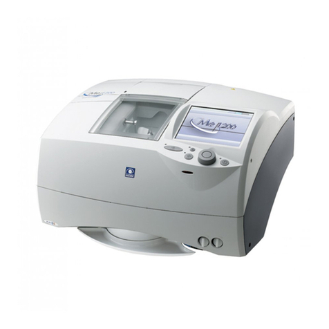
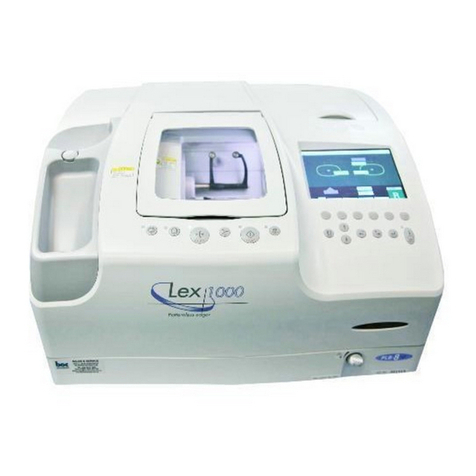
Nidek Medical ME-1000 User manual

NIDEK
MULTIFUNCTION EDGER
Model ME-1000
SERVICE MANUAL
September,2005
LLE11ARDA001A/E
134 pages in Total

NIDEK CO., LTD. : 34-14, Maehama, Hiroishi-cho, Gamagori, Aichi 443-0038, Japan
(Manufacturer) Telephone: (0533) 67-6611
Facsimile: (0533) 67-6610
NIDEK CO., LTD : 6th Floor, Takahashi Bldg., No.2, 3-chome, Kanda-jinboucho
(Tokyo Office) Chiyoda-ku, Tokyo 101-0051, Japan
Telephone: (03) 3288-0571
Facsimile: (03) 3288-0570
Telex: 2226647 NIDEK J
NIDEK INCORPORATED : 47651 Westinghouse Drive, Fremont, California 94539, U. S. A.
(United States Agent) Telephone: (510) 226-5700
Facsimile: (510) 226-5750
NIDEK SOCIETE ANONYME : Europarc 13, rue Auguste Perret, 94042 CRETEIL, France
(Authorized Representative) Telephone: (01) 49 80 97 97
Facsimile: (01) 49 80 32 08

Page
Table of Contents
§
1INTRODUCTION ........................................................................................................1-1
§
2SAFETYPRECAUTIONS ............................................................................................2-1
2.1GeneralPrecautions....................................................................................................2-1
§
3TROUBLESHOOTING................................................................................................3-1
§
4SUBTROUBLESHOOTING ....................................................................................... 4-1
4.1 The Starting Screen does notAppear. .........................................................................4-1
4.2TheInitializationdoesnotStart. ..................................................................................4-3
4.3 The Error MessageAppears. ......................................................................................4-4
4.3.1.1 Error 101-Roughing was not completed is displayed. ............................4-7
4.3.1.2 Error 102-Finishing was not completed is displayed. .............................4-8
4.3.2.1 201-Feeler off error is displayed............................................................4-9
4.3.2.2 202-There is no lens is displayed. ........................................................ 4-11
4.3.2.3 203-Feeler lift error is displayed. .........................................................4-12
4.3.2.4 Error 204-Front and rear data crossed is displayed..............................4-14
4.3.2.5 205-Start & end measure data error is displayed. ................................4-15
4.3.3.1401-XYRInitialize errorisdisplayed. ..................................................4-16
4.3.3.2402-X Initializeerror is displayed. .......................................................4-16
4.3.3.3403-YInitialize error isdisplayed.........................................................4-17
4.3.3.4404-R Initializeerror is displayed.........................................................4-18
4.3.3.5405-XYInitializeerror isdisplayed. .....................................................4-19
4.3.3.6406-XR Initialize erroris displayed. .....................................................4-19
4.3.3.7407-YR Initialize erroris displayed. .....................................................4-19
4.3.3.8408-Frontfeeler Initializeerroris displayed..........................................4-20
4.3.3.9409-Rear feeler Initializeerror is displayed...........................................4-21
4.3.3.10410-DrillZRInitializeerrorisdisplayed. ............................................4-22
4.3.3.11 411-DrillZInitializeerrorisdisplayed. ...............................................4-22
4.3.3.12412-DrillRInitializeerrorisdisplayed. ..............................................4-23
4.3.3.13413-SFB Initialize error is displayed. .................................................4-24
4.3.4.1 501-Chuck origin error is displayed. ....................................................4-25
4.3.5.1 Error 601-Main wheel was not rotate is displayed................................4-26
4.3.5.2
Drill/Cutterrotationerrorisdisplayed(onlyfortheformerversionsthanV1.10)..........
4-27
4.3.5.3 Error 603-SFB wheel was not rotate is displayed. ...............................4-28
4.3.6.1 701-Cover open error is displayed. .....................................................4-29
4.3.6.2 702-Cover close error is displayed. .....................................................4-30
4.4The maintenancemessage appears............................................................................4-30
4.5 The System cannot be Operated with the Switches on the Control Panel....................4-31
4.6 The System cannot be operated with theToutch Panel...............................................4-32

4.7 The Feeler does notTouch the Lens..........................................................................4-33
4.7.1 The front feeler does not touch the lens. ...........................................................4-33
4.7.2 The rear feeler does not touch the lens. ............................................................4-33
4.8 The Lens Processing cannot be Performed Properly. .................................................4-34
4.8.1 Water leaks.....................................................................................................4-35
4.8.2 Water does not run..........................................................................................4-35
4.8.3Axis shiftoccurs. .............................................................................................4-36
4.8.4Processingtimeislong.....................................................................................4-36
4.8.5 The bevel position is not proper. ......................................................................4-37
4.8.6 The SFB position is not proper. .......................................................................4-38
4.8.7 The groove position is not proper.....................................................................4-39
4.8.8Unpolished parts areleft inthepolishing process ..............................................4-40
4.8.9Thedrillingpositionisnotproper. ....................................................................4-40
§
5REMOVINGPROCEDURE........................................................................................ 5-1
5.1 Opening the top coverAS ..........................................................................................5-1
5.2 Removingthe front cover ............................................................................................5-1
5.3Removing the side cover R .........................................................................................5-1
5.4Removing the side cover L..........................................................................................5-2
5.5Removing therear cover .............................................................................................5-2
5.6 Removing the top coverAS ........................................................................................5-2
§
6REPLACEMENTPROCEDURE................................................................................ 6-1
6.1Replacing thePrinted Board .......................................................................................6-1
6.1.1 Replacing the BA01 printed board.....................................................................6-1
6.1.2 Replacing the printed board BA02.....................................................................6-1
6.1.3 Replacing the printed board BA03.....................................................................6-2
6.1.4 Replacing the printed board BA04.....................................................................6-2
6.1.5 Replacing the printed board BA05.....................................................................6-3
6.1.6 Replacing the printed board BA06.....................................................................6-3
6.1.7 Replacement of the printed board BA07 ............................................................6-3
6.1.7.1Replacing the printedboard 07 ofthe left lens measuringAS ..................6-3
6.1.7.2Replacing theprinted boardBA07 ofthe rightlens measuringAS ...........6-4
6.1.8 Replacing the printed board BA08.....................................................................6-4
6.1.9 Replacing the printed board BA09.....................................................................6-5
6.1.10 Replacing the printed board BA11 ...................................................................6-5
6.2ReplacingtheGrindingWheelAS ...............................................................................6-6
6.3ReplacingtheLens Clamp ..........................................................................................6-6
6.4Replacing theLensAdapter ........................................................................................6-7
6.5Replacing the PowerSwitch .......................................................................................6-7
6.6ReplacingtheSwitchingRegulator...............................................................................6-8
6.7 Replacingthe Inverter .................................................................................................6-9
6.8Replacing the Color LCD Module ..............................................................................6-9
6.9 ReplacingtheLensMeasuringAS .............................................................................6-10
6.9.1ReplacingtheleftlensmeasuringAS ................................................................6-10
6.9.2ReplacingtherightlensmeasuringAS ..............................................................6-10
Page

Page
6.10Replacingthe SpindleAS........................................................................................ 6-11
6.11ReplacingtheGroovingandDrillingAS ...................................................................6-12
6.12 Replacing the SFBAS ............................................................................................6-13
6.13 Replacing the Ganged Water Supply PipeAS..........................................................6-14
6.14 Replacing the Upper Processing ChamberAS .........................................................6-15
6.15Replacing the LowerProcessing ChamberAS.........................................................6-16
6.16Replacing theCarriageAS ......................................................................................6-17
6.17Replacing theYAxisAS .........................................................................................6-17
6.18Replacingthe LeftFeeler ........................................................................................6-18
6.19ReplacingtheRightFeeler ......................................................................................6-19
6.20 Replacing the DC Motor ........................................................................................6-20
6.20.1Replacing theDC motorof the left lens measuringAS ....................................6-20
6.21Replacing the RotaryEncoder.................................................................................6-21
6.21.1Replacing therotary encoder ofthe leftlens measuringAS..............................6-21
6.21.2Replacing the rotaryencoder of theright lensmeasuringAS............................6-21
6.22 Replacing theAlfa Step Motor................................................................................6-21
6.22.1 Replacing theAlfa step motor for the X axis ...................................................6-21
6.22.2Replacing theAlfa stepmotor for theYaxis ...................................................6-22
6.22.3 Replacing theAlfa step motor for the θaxis....................................................6-23
6.22.4Replacing theAlfastep motor ........................................................................6-24
6.23Replacing the PulseMotor Driver ...........................................................................6-25
6.23.1Replacing theAlfa step motor driver for the X axis .........................................6-25
6.23.2Replacing theAlfastep motor driver for theYaxis..........................................6-25
6.23.3 Replacing theAlfa step motor driver for the θaxis ..........................................6-26
6.23.4 Replacing theAlfa step motor driver for CHUCK ..........................................6-26
6.24Replacing the Spindle MotorAS .............................................................................6-27
6.25Replacing the Inverter for theBL Motor ..................................................................6-27
6.26 Replacing the DC Motor with Encoder ...................................................................6-28
6.26.1 Replacing the DC motor with encoder for the SFBAS ...................................6-28
6.26.2Replacingthe DC motorforthe grooving&drillingAS...................................6-28
6.27 Replacing the Pulse Motor of the Electric Operated CoverAS (40350-E020) .........6-29
6.28 Replacing the Chuck MotorAS ..............................................................................6-29
6.29Replacing theMiter Gear........................................................................................6-30
6.30ReplacingtheEnd Mill ............................................................................................6-30
6.31Replacingthe Cutter ...............................................................................................6-31
6.32Replacing theFuses ................................................................................................6-31
6.33 Replacing the PowerAS .........................................................................................6-32
6.34 Replacing the Cable CA33 .....................................................................................6-32
§
7ADJUSTMENT............................................................................................................. 7-1
7.1EstablishingtheAdjustmentMode...............................................................................7-1
7.1.1EstablishingtheMenumode ..............................................................................7-1
7.1.2EstablishingtheParameterSettingmode ............................................................7-1
7.1.3EstablishingtheSystemSettingmode .................................................................7-2
7.2VerificationbeforeAdjustment ....................................................................................7-3
7.2.1Verifyingthewheeltype .....................................................................................7-3
7.2.2 Checking the chuck pressure .............................................................................7-3

Page
7.2.3Dressingwheel ..................................................................................................7-4
7.2.3.1Dressing................................................................................................7-4
7.2.3.2 Compound............................................................................................7-5
7.2.4 Reading the lens data.........................................................................................7-5
7.2.5Readingthedataofthedrillingadjustmentlens ...................................................7-6
7.3Calibration .................................................................................................................7-6
7.4FeelerAdjustment ......................................................................................................7-7
7.4.1Adjustingthefeelerheight ..................................................................................7-7
7.4.2AdjustingthefeelerAXIS ..................................................................................7-8
7.5SizeAdjustment........................................................................................................7-10
7.6AdjustingtheBevelPosition ...................................................................................... 7-11
7.7AXISAdjustment .....................................................................................................7-12
7.8PolishingAdjustment.................................................................................................7-13
7.8.1PolishDiff.andBeveladjustments ...................................................................7-13
7.8.2AdjustingthepolishingAXIS ...........................................................................7-14
7.8.3AdjustingthePolishSize ..................................................................................7-15
7.9Adjustment oftheSafety Bevel .................................................................................7-16
7.9.1Adjustingthe S.F.B.position............................................................................7-16
7.9.2Adjustmentof theSafety BevelAXIS ..............................................................7-17
7.9.3AdjustingtheSafetyBevelposition(Flat) .........................................................7-18
7.9.4Adjusting theSafetyBevelAXIS (Polish) .........................................................7-19
7.10GrooveAdjustment ................................................................................................7-20
7.10.1Adjustingthegroovingdepth..........................................................................7-20
7.10.2Adjustingthegrooveposition .........................................................................7-21
7.10.3Adjusting the GrooveAXIS ...........................................................................7-22
7.11DrillingAdjustment..................................................................................................7-23
7.11.1Preparationforthedrillingadjustment.............................................................7-23
7.11.2AdjustingtheHoleDiameter ..........................................................................7-24
7.11.3AdjustingtheDrillingAXISandverticalcentering ...........................................7-25
7.11.4AdjustingtheDrillZeroPoint(Z) ...................................................................7-26
7.11.5Adjusting theFront SurfaceOffset .................................................................7-27
7.11.6Adjusting thehole depth.................................................................................7-28
7.12Updating the Software ............................................................................................7-29
7.13Checking the Parameterof the BLInverter ..............................................................7-29
7.14 Test Mode .............................................................................................................7-30
7.15PositionadjustmentoftheleftmeasuringASshadingplate .......................................7-32
7.16PositionadjustmentoftherightmeasuringASshadingplate .....................................7-32
7.17Calibration ofthe touch panel..................................................................................7-33
7.18Changingtheparameters.........................................................................................7-33
§
8SUPPLEMENT .............................................................................................................8-1
8.1WiringDiagram ..........................................................................................................8-1
8.2 Connector Cable........................................................................................................8-2
8.3Appearance................................................................................................................8-4
8.4 Labels ........................................................................................................................8-5
8.5 Error message ............................................................................................................8-7
8.6Parameter List ............................................................................................................8-8
8.7Parameter List ofInverter .........................................................................................8-14
1 - 1
LLE11ARDA001A/E
§1 INTRODUCTION
• This service manual provides information for after-sales service for the NIDEK multifunction
edger, model: ME-1000.
• Technical contents for producing eyeglass lenses are not contained in this manual.
• For proper after-sales service, it is necessary to understand this manual thoroughly before
servicing.
• Refer to the NIDEK multifunction edger, model: ME-1000 Operator’s Manual and Parts List.
• Specifications are subject to change without notice for improvement. As for important changes,
refer to the Technical Bulletins (T.B.).
• In case the device cannot be repaired according to the procedures described in this manual,
please tell us the serial number of the device and details of the symptom or symptoms.

1 - 2
LLE11ARDA001A/E

2 - 1
LLE11ARDA001A/E
§2 SAFETY PRECAUTIONS
2.1 General Precautions
• Only the service persons who are accustomed to using tools, and have a deep knowledge of
this instrument are allowed to repair the instrument.
• Proceed right work in accordance with the procedure.
If not, accidents or failure of the instrument may result.
• When the instrument is moved, it should be carried by two or more persons. Otherwise, you
may have a backache or fall down.
• When performing maintenance works, turn off the power switch, and disconnect the power
cord from the wall outlet unless necessary.
• Never wipe the covers, etc. using an organic solvent such as a paint thinner.
The surface may be ruined, and as a result, the appearance of the instrument will be impaired.
<Maintenance precautions>
• In case of instrument malfunction, turn the power switch off after checking the symptom.
• Never drop parts or screws inside the instrument, nor bump it against the surrounding objects.
• Have storage cases ready to ensure the loss of the removed screws or parts.
• In screwing or unscrewing, use a proper tool for the screw.
• After loosening the screws fixed by a threadlocking adhesive, and tightening them again, be
sure to apply the threadlocking adhesive to them.
• After replacing parts, make sure that they are fixed securely before turning on the power.
• If you observe strange odors or smoke being emitted from the instrument, immediately turn
off the instrument and locate the causes after disconnecting the power cord from the wall-
outlet.
If the instrument is continuously powered under such abnormal conditions, a fire, electric
shock or total loss of the instrument may result.
• Referring to “8.1 Wiring Diagram” and “8.2 Connector Cables”, check cables for the following:
1. Connectors are connected securely.
2. No contact failure occurs after re-connection of connectors.
3. No failure in soldering
Do not pull the cables strongly. It may cause a breaking of wire.

2 - 2
LLE11ARDA001A/E
• Never work with wet hands.
It may result in an electric shock or instrument malfunction.
• Avoid spraying water into the instrument.
• Do not exert excessive force to the stylus of the tracing unit.
It may cause a deformation of the stylus or instrument malfunction.
• Before grinding, select and specify a proper lens material to be ground.
In case of improper selection of the lens material, the lens to be ground may break or grinding
wheels may become damaged.
• Never fail to shut the soundproof cover while the wheels are turning.
Otherwise, grinding splash may get in your eye and hurt it.
• While rotating wheels and V belt, never bring your hand or face near to them.
It may hurt your hand and face.
• Replacement of the wheel must be done after cleaning the wheel and the wheel housing,
wearing gloves to protect your hand from ground powder.
• After grinding a glass lens, chamfer each ground edge of the front and rear side of the lens.
After grinding, glass lenses may have fine burrs. They may hurt your skin.
• Do not use a calibration jig for other usage described in this manual.

3 - 1
LLE11ARDA001A/E
§3 TROUBLESHOOTING
Turn on the power switch.
Does the initialization start?
Does the starting screen appear?
Does any error message appear?
Can the lens measurement be performed properly?
Can the lens processing be performed properly?
Turn off the power switch.
Completion
4.2 The Initialization does not Start.
4.1 The Starting Screen does not Appear.
4.7 The Feeler does not Contact to the Lens.
4.8 The Lens Processing cannot be Performed
Properly.
Yes
Yes
Yes
No
Yes
No
No
No
No
4.3 The Error Message Appears.
Yes
Can the system be operated with the switches on the
control panel? 4.5 The System cannot be Operated with the Switches
on the Control Panel.
Yes
No
Does the maintenance message “Please Clean Tank &
Pump and Replace Filter”appear?
No
4.4 The Maintenance Message Appears.
Yes
Can the system be operated with the touch panel? 4.6 The System cannot be Operated with the Touch
Panel.
Yes
No

3 - 2
LLE11ARDA001A/E

4 - 1
LLE11ARDA001A/E
§4 SUBTROUBLESHOOTING
4.1 The Starting Screen does notAppear.
Use the wall outlet which can supply the proper power
supply voltage.
Is the power supply voltage of the wall outlet proper?
Do the fuses blow?
Is the voltage between 1a-2a terminals of the power
switch (80460-00123) AC100V when turning the
power on?
Is the voltage between 1-3 terminals of the noise filter
(80404-00043) AC100V?
Is the voltage between N-L terminals of the connector
CN1 for the switching regulator (80602-00101)
AC100V?
Are the voltages between 5-1 (6-2) and 7-3 (8-4) pins
of the connector CN51 for the switching regulator
(80602-00101) DC+24V?
Is the voltage between 1-4 (2-5) pins of the connector
P201 (J2) on the BA02 board (40350-BA02)
DC+24V?
Is the voltage of the connector on the BA02 board
(40350-BA02) as described below?
Connector P202(J2)
Between 1-2 pins:DC+12V
Between 3-4 pins:DC+5V
Is the voltage of the connector P101 (J1) on the BA01
board (40350-BA01) as described below?
Between 1-2 pins:DC+12V
Between 3-4 pins:DC+5V
Replace the blown fuse with the new one.
(See 6.32.)
Replace the power switch (80460-00123) with the new
one.
(See 6.5)
Replace the cable CA03 (40350-CA03) with the new
one.
Replace the switching regulator (80602-00101) with
the new one.
(See 6.6.)
Replace the CA09 cable (40350-CA09) with the new
one.
Replace the BA02 board (40350-BA02) with the new
one.
(See 6.1.2.)
Replace the CA11 cable (40350-CA11) with the new
one.
No
Yes
Yes
Yes
Yes
Yes
Yes
Yes
No
Yes
Yes
No
No
No
No
No
No
Replace the cable CA02 (40350-CA02) with the new
one.
No

4 - 2
LLE11ARDA001A/E
Is the voltage of the P103 (J3) connector on the BA01
board (40350-BA01) as described below?
Between 7A-5A(7B-5B、8A-6A) pins: DC+3.3V
Between 19A-19B(20A-20B) pins:DC+12V
Is the voltage of the P301 (J1) connector on the BA03
board (40350-BA03) as described below?
Between 7A-5A(7B-5B、8A-6A) pins:DC+3.3V
Between 19A-19B(20A-20B) pins:DC+12V
Is the voltage between 1-3(2-4) pins of the P302
connector on the BA03 board (40350-BA03)
DC+3.3V, and between 1-2 pins of the P303 connector
DC+12V?
Does the LCD cable (40273-E022) break?
Does the CA30 cable (40350-CA30) break?
Replace the color LCD module (42203-E016) with the
new one.
(See 6.8.)
Replace the BA01 board (40350-BA01) with the new
one.
(See 6.1.1.)
Replace the CA28 cable (40350-CA28) with the new
one.
Replace the LCD cable (40273-E022) with the new
one.
Replace the CA30 cable (40350-CA30) with the new
one.
Yes
No
No
Yes
Yes
No
No
Yes
Yes
Replace the BA03 board (40350-BA03) with the new
one.
(See 6.1.3.)
No
Replace the inverter (42203-E017) with the new one.
(See 6.7.)
Is the symptom improved? Completion
No
Yes
Replace the BA01 board (40350-BA01) with the new
one.
(See 6.1.1.)
Is the symptom improved? Completion
No
Yes

4 - 3
LLE11ARDA001A/E
4.2 The Initialization does not Start.
Replace the CA12 cable (40350-CA12) with the new
one.
Does the CA12 cable (40350-CA12) break?
Replace the BA01 board (40350-BA01) with the new
one.
(See 6.1.1.)
Is the symptom improved?
Replace the BA02 board (40350-BA02) with the new
one.
(See 6.1.2.)
Completion
No
Yes
No
Yes

4 - 4
LLE11ARDA001A/E
4.3 The Error MessageAppears.
4.3.1.1 Error code 101-Roughing was not completed is
displayed.
Is the error code 101-Roughing was not completed
displayed? Yes
No
4.3.1.2 Error code 102-Finishing was not completed is
displayed.
Is the error code 102-Finishing was not completed
displayed? Yes
No
4.3.2.1 Error code 201-Feeler off error is displayed.Is the error code 201-Feeler off error displayed? Yes
No
4.3.2.2 Error code 202-There is no lens is displayed.Is the error code 202-There is no lens displayed? Yes
No
4.3.2.3 Error code 203-Feeler lift error is displayed.Is the error code 203-Feeler lift error displayed? Yes
No
4.3.2.4 Error code 204-Front & rear data crossed is
displayed.
Is the error code 204-Front & rear data crossed
displayed? Yes
No
4.3.2.5 Error code 205-Start & end measure data error
is displayed.
Is the error code 205-Start & end measure data error
displayed? Yes
No
4.3.3.1 Error code 401-XYR Initialize error is
displayed.
Is the error code 401-XYR Initialize error displayed? Yes
No
4.3.3.2 Error code 402-X Initialize error is displayed.Is the error code 402-X Initialize error displayed? Yes
No
4.3.3.3 Error code 403-Y Initialize error is displayed.Is the error code 403-Y Initialize error displayed? Yes
No

4 - 5
LLE11ARDA001A/E
4.3.3.4 Error code 404-R Initialize error is displayed.Is the error code 404-R Initialize error displayed? Yes
No
4.3.3.5 Error code 405-XY Initialize error is displayed.Is the error code 405-XY Initialize error displayed? Yes
No
4.3.3.6 Error code 406-XY Initialize error is displayed.Is the error code 406-XY Initialize error displayed? Yes
No
4.3.3.7 Error code 407-YR Initialize error is displayed.Is the error code 407-YR Initialize error displayed? Yes
No
4.3.3.8 Error code 408-Front feeler Initialize error is
displayed.
Is the error code 408-Front feeler Initialize error
displayed? Yes
No
4.3.3.9 Error code 409-Rear feeler Initialize error is
displayed.
Is the error code 409-Rear feeler Initialize error
displayed? Yes
No
4.3.3.10 Error code 410-Drill ZR Initialize error is
displayed.
Is the error code 410-Drill ZR Initialize error
displayed? Yes
No
4.3.3.11 Error code 411-Drill Z Initialize error is
displayed
Is the error code 411-Drill Z Initialize error displayed? Yes
No
4.3.3.12 Error code 412-Drill R Initialize error is
displayed.
Is the error code 412-Drill R Initialize error displayed? Yes
No
4.3.3.13 Error code 413-SFB Initialize error is
displayed.
Is the error code 413-SFB Initialize error displayed? Yes
No

4 - 6
LLE11ARDA001A/E
4.3.4.1 Error code 501-Chuck origin error is displayed.Is the error code 501-Chuck origin error displayed? Yes
No
4.3.5.1 Error code 601-Main wheel was not rotate is
displayed.
Is the error code 601-Main wheel was not rotate
displayed? Yes
No
4.3.5.3 Error code 603-SFB wheel was not rotate is
displayed.
Is the error code 603-SFB wheel was not rotate
displayed?
Yes
No
4.3.6.1 Error code 701-Cover open error is displayed.Is the error code 701-Cover open error displayed? Yes
No
4.3.6.2 Error code 7102-Cover close error is displayed.Is the error code 702-Cover close error displayed? Yes
No
Completion
Is the error code 602-Drill/Cutter was not rotate
displayed (only for the former versions than V1.10)?
4.3.5.2 Error code 602-Drill/Cutter was not rotate is
displayed (only for the former versions than
V1.10).
Yes
No

4 - 7
LLE11ARDA001A/E
4.3.1.1 Error 101-Roughing was not completed is displayed.
Is the voltage between 1-2 pins of the MD02 connector
of the CA44 cable (40350-CA44) DC+24V?
Does the CA17 cable (40350-CA17) break?
Replace the CA44 cable (40350-CA44) with the new
one.
Replace the CA17 cable (40350-CA17) with the new
one.
No
Yes
Yes
No
Is the symptom improved?
Does the Y axis move smoothly when checking its
operation by hand?
Replace the alfa step pulse motor for Y axis (40347-
E030) with the new one.
(See 6.23.2.)
Is the symptom improved?
Completion
Does the alfa step pulse motor (40347-E030) break?
Replace the Y axis AS (40350-5300) with the new one.
(See 6.17.)
Replace the Y axis AS (40350-5300) with the new one.
(See 6.17.)
Yes
No
Yes
No
No
Yes
Replace the BA02 board (40350-BA02) with the new
one.
(See 6.1.2.)
No
Is the voltage between 1-3(2-4) pins of the P902(J2)
connector on the BA09 board (40350-BA09)
DC+24V?
Replace the CA09 cable (40350-CA09) with the new
one.
Yes
No
Is the voltage between 1-2, 3-4, 5-6, 7-8 pins of the
P909(J9) connector on the BA09 board (40350-BA09)
DC+24V?
Replace the BA09 board (40350-BA09) with the new
one.
(See 6.1.9.)
Yes
No
Completion
Yes
Dress the wheel.
(See 7.2.3.)
Is the parameter value of the maximum processing
rotation numbers 40?
Yes
No Select 40 of the maximum processing rotation
numbers.

4 - 8
LLE11ARDA001A/E
4.3.1.2 Error 102-Finishing was not completed is displayed.
Is the symptom improved?
Return the system to NIDEK.
No
Completion
Yes
Dress the wheel.
(See 7.2.3.)
Is the maximum processing rotation number 40? Select 40 of the maximum processing rotation number.
No
Yes
Check the operation of the Y axis by hand when the X
axis of the carriage is located in the finishing position.
Do the cables interfere with the mechanical parts?
Place the cables that interfere with the mechanical
parts.
No
Yes
Table of contents
Other Nidek Medical Edger manuals

Nidek Medical
Nidek Medical LE-9000SX User manual

Nidek Medical
Nidek Medical SE-9090 Supra User manual

Nidek Medical
Nidek Medical LE-700 Instruction sheet

Nidek Medical
Nidek Medical LE-700 User manual

Nidek Medical
Nidek Medical Le 1000 User manual

Nidek Medical
Nidek Medical LE-9000LX User manual

Nidek Medical
Nidek Medical Lex 1000 User manual

Nidek Medical
Nidek Medical LE-700 User manual

Nidek Medical
Nidek Medical LE-9000EX Express User manual

Nidek Medical
Nidek Medical SE-9090 Express User manual