Vista Pro 2250 User manual

INSTALLATION INSTRUCTIONS
1625 Surveyor Avenue • Simi Valley, CA 93063 • (805) 527-0987 • (800) 766-VISTA (8478)
FAX: (888) 670-VISTA (8478) • [email protected] • www.vistapro.com
FOR USE ONLY WITH LOW VOLTAGE LANDSCAPE POWER UNITS THAT DO NOT EXCEED 25 AMPS, 15 VOLT MAXIMUM.
WARNING: Luminaires must be installed in accordance with the National Electrical Code (NEC) and local codes. Failure to do so will void the warranty and may
result in serious injury and/or damage to the luminaire.
SAFETY WARNING: Luminaire can become very hot depending on lamp wattage used. Lens and metal around lamp can become hot enough to blister hands.
Particular care should be taken not to locate luminaires where small children can reach them if high wattage lamps are used.
LUMINAIRES ARE NOT TO BE INSTALLED WITHIN 10 FT. (3.05M) OF A POOL OR SPA. SECONDARY CABLE IS NOT TO BE BURIED MORE THAN 6”.
WHEN USING MULTIPLE LUMINAIRES, LOAD IS NOT TO EXCEED THE TOTAL WATTS OF TRANSFORMER RATING. DO NOT USE EXTENSION CORDS
ON POWER UNITS.
NOTE: Always use UL recognized wire connectors for connections.
LUMINAIRE IS UL LISTED FOR ABOVE GROUND INSTALLATION ONLY.
Silicone Fille
d
Safety Connectors
36” Pigtail
Adjustable Knuckle
Housing
Shroud
Main Supply Cable
Ground Stake
Vista Professional Outdoor Lighting reserves the right to modify the design and/or construction of the fixture shown without further notification.
LUMINAIRE MOUNTING:
1. To prevent electrical shock, disconnect transformer from electrical supply
before installation or service.
2. Run wire pigtail from luminaire through mounting hole in top of ground
stake.
3. Thread luminaire into threaded hole in ground stake.
4. Place stake in desired position and insert into ground until ange of stake is
ush to grade.
5. Strip two leads from luminaire pigtail wire. Using two silicone lled safety
connectors, connect leads from luminaire to main supply cable leads.
NOTE: Luminaires are supplied with 36” of 18-2 cable pigtail for secure
connection to main supply cable. The wire is to be protected by routing in close
proximity to the luminaire. The wiring should be buried a maximum depth of 6
inches (15.2 cm) in order to connect to the main supply cable.
6. Aim luminaire to desired angle. Lock into place by tightening Phillips screw
in adjustable knuckle.
NOTE: Avoid aiming xture directly upward. Whenever possible, set at angle
to prevent rain or irrigation water from settling on lens.
NOTE: All luminaires orientation must be so that every part of the lampholder
and the lamp are greater than 2” from the ground plane.
LAMP INSTALLATION/REPLACEMENT:
CAUTION: Do not exceed maximum wattage marked on luminaire label.
1. To prevent electrical shock, disconnect transformer from electrical supply
before service.
2. Remove shroud to expose lamp.
3. Replace lamp with correct wattage and type marked on xture label.
NOTE: DO NOT touch lamp with bare hands. Always use soft cloth or the
plastic wrapping (if available) from lamp to handle the lamp.
4. Re-install shroud.
WARNING: TO REDUCE THE RISK OF FIRE, OR INJURY TO PERSONS:
1. Turn off/unplug and allow to cool before replacing lamp.
2. Lamps get hot quickly! Contact only switch/plug when turning on.
3. Do not touch hot lens, guard or enclosure.
4. Keep lamp away from material that may burn.
5. Do not touch the lamp at any time. Use a soft cloth. Oil from the skin may
damage lamp.
6. Do not operate luminaire tting with a missing or damaged cover.
IMPORTANT SAFETY INSTRUCTIONS - THE LIGHTED LAMP IS HOT!
SAVE THESE INSTRUCTIONS (Leave with property owner/manager)
SEE REVERSE FOR LED
Up & Accent Lights
Landscape Series
2250

INSTALLATION INSTRUCTIONS
1625 Surveyor Avenue • Simi Valley, CA 93063 • (805) 527-0987 • (800) 766-VISTA (8478)
FAX: (888) 670-VISTA (8478) • [email protected] • www.vistapro.com
FOR USE ONLY WITH LOW VOLTAGE LANDSCAPE POWER UNITS THAT DO NOT EXCEED 25 AMPS, 15 VOLT MAXIMUM.
WARNING: Luminaires must be installed in accordance with the National Electrical Code (NEC) and local codes. Failure to do so will void the warranty and may
result in serious injury and/or damage to the luminaire.
SAFETY WARNING: Luminaire can become very hot depending on lamp wattage used. Lens and metal around lamp can become hot enough to blister hands.
Particular care should be taken not to locate luminaires where small children can reach them if high wattage lamps are used.
LUMINAIRES ARE NOT TO BE INSTALLED WITHIN 10 FT. (3.05M) OF A POOL OR SPA. SECONDARY CABLE IS NOT TO BE BURIED MORE THAN 6”.
WHEN USING MULTIPLE LUMINAIRES, LOAD IS NOT TO EXCEED THE TOTAL WATTS OF TRANSFORMER RATING. DO NOT USE EXTENSION CORDS
ON POWER UNITS.
NOTE: Always use UL recognized wire connectors for connections.
LUMINAIRE IS UL LISTED FOR ABOVE GROUND INSTALLATION ONLY.
Silicone Fille
d
Safety Connectors
36” Pigtail
Adjustable Knuckle
Housing
Shroud
Main Supply Cable
Ground Stake
Vista Professional Outdoor Lighting reserves the right to modify the design and/or construction of the fixture shown without further notification.
LUMINAIRE MOUNTING:
1. To prevent electrical shock, disconnect transformer from electrical supply
before installation or service.
2. Run wire pigtail from luminaire through mounting hole in top of ground
stake.
3. Thread luminaire into threaded hole in ground stake.
4. Place stake in desired position and insert into ground until ange of stake is
ush to grade.
5. Strip two leads from luminaire pigtail wire. Using two silicone lled safety
connectors, connect leads from luminaire to main supply cable leads.
NOTE: Luminaires are supplied with 36” of 18-2 cable pigtail for secure
connection to main supply cable. The wire is to be protected by routing in close
proximity to the luminaire. The wiring should be buried a maximum depth of 6
inches (15.2 cm) in order to connect to the main supply cable.
6. Aim luminaire to desired angle. Lock into place by tightening Phillips screw
in adjustable knuckle.
NOTE: Avoid aiming xture directly upward. Whenever possible, set at angle
to prevent rain or irrigation water from settling on lens.
NOTE: All luminaires orientation must be so that every part of the lampholder
and the lamp are greater than 2” from the ground plane.
2250 04.16
WARNING: TO REDUCE THE RISK OF FIRE, OR INJURY TO PERSONS:
1. Turn off/unplug and allow to cool before replacing lamp.
2. Lamps get hot quickly! Contact only switch/plug when turning on.
3. Do not touch hot lens, guard or enclosure.
4. Keep lamp away from material that may burn.
5. Do not touch the lamp at any time. Use a soft cloth. Oil from the skin may
damage lamp.
6. Do not operate luminaire tting with a missing or damaged cover.
IMPORTANT SAFETY INSTRUCTIONS - THE LIGHTED LAMP IS HOT!
SAVE THESE INSTRUCTIONS (Leave with property owner/manager)
SEE REVERSE FOR INCANDESCENT
COVER LOCKING SCREW
FIXTURE COVER
LOCKING RING
FIELD REPLACEABLE
LED ENGINE
MALE CONNECTOR
FEMALE
CONNECTOR
FIXTURE BASE &
KNUCKLE ASSEMBLY
SILICONE O-RING
LED ENGINE INSTALLATION/REPLACEMENT:
1. To prevent electrical shock, disconnect transformer from electrical supply
before service.
2. Loosen shroud locking screw.
3. Remove shroud to expose eld replaceable LED engine.
4. Remove stainless steel locking/expansion ring.
5. Pull up LED engine assembly out of xture body.
6. Disconnect Connector Assembly.
7. Connect new Field Replaceable LED Engine to Connector Assembly.
8. Re-install LED base assembly onto xture body.
9. Re-install stainless steel locking/expansion ring.
10. Re-install shroud and locking screw.
Up & Accent Lights-LED
Landscape Series
2250
Table of contents
Other Vista Pro Landscape Lighting manuals
Popular Landscape Lighting manuals by other brands
LIGMAN
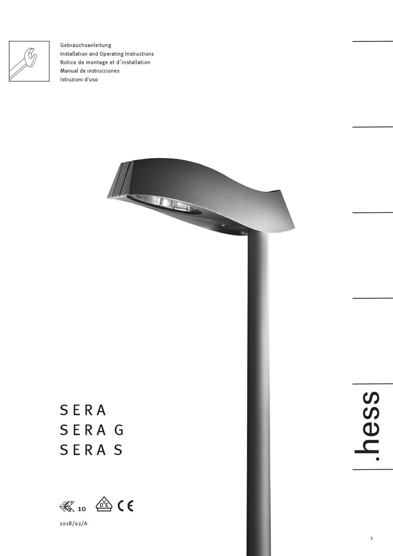
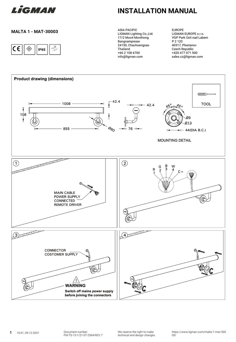
LIGMAN MALTA 1 installation manual

Saxby Lighting
Saxby Lighting Islay 68784 Instruction leaflet
LIGMAN
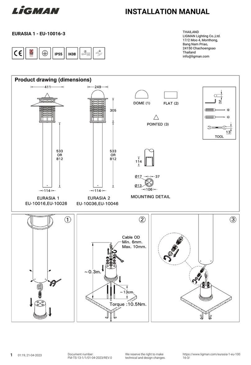
LIGMAN EU-10016-3 installation manual

LIGMAN
LIGMAN KI-60475 installation manual
Cooper Lighting
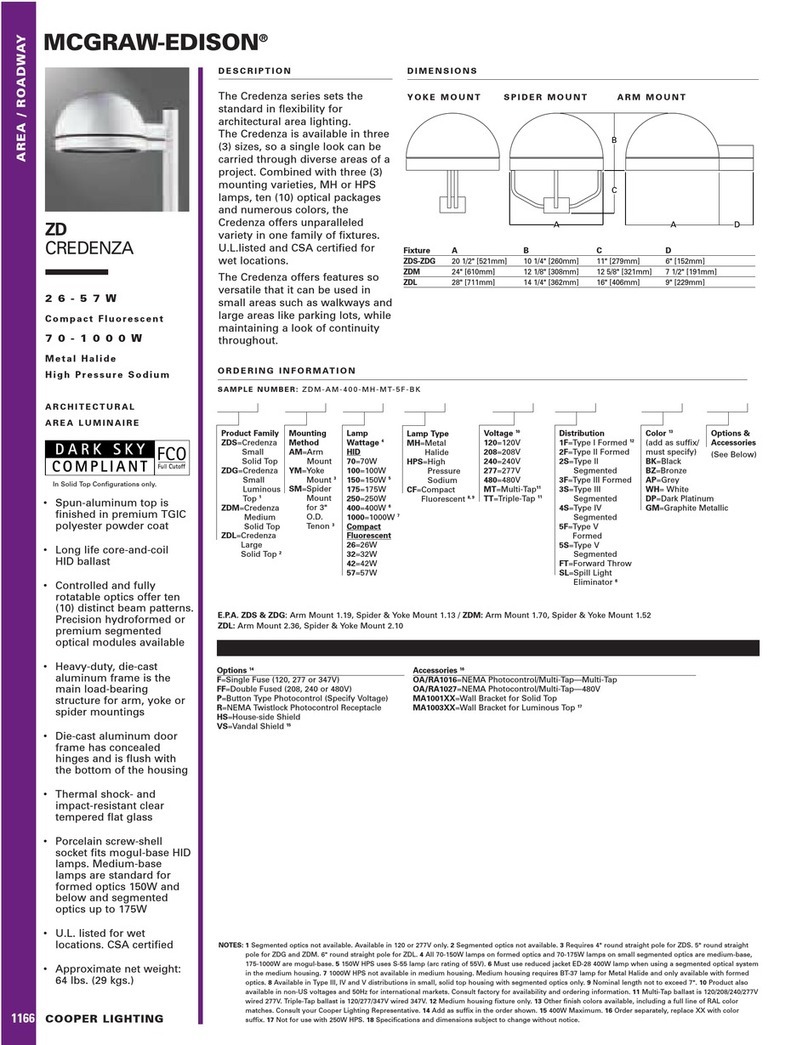
Cooper Lighting McGraw-Edison ZD Credenza specification
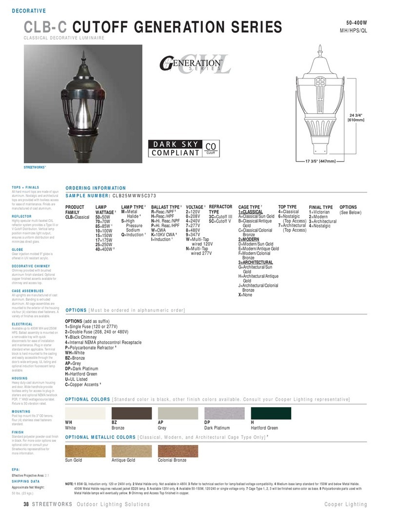
Cooper Lighting
Cooper Lighting Generation CLB25MWW5C373 Specification sheet
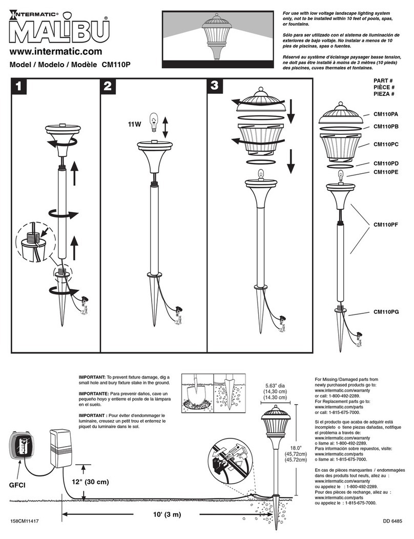
Malibu Boats
Malibu Boats CM110P instructions

AMP Lighting
AMP Lighting OrchardPro APL-3018-B-BZ Installation & maintenance guide
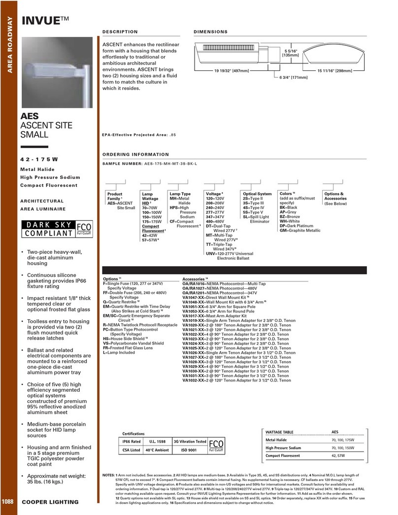
Cooper Lighting
Cooper Lighting Invue 42 - 175W Specification sheet
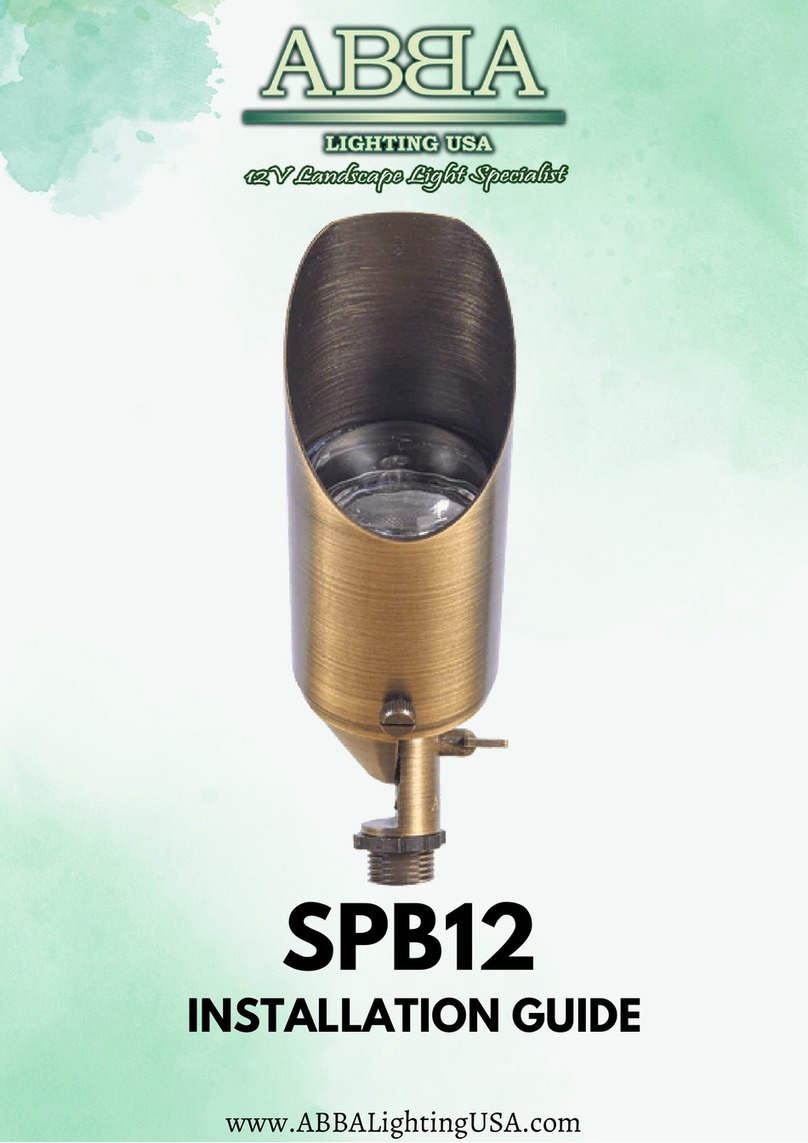
ABBA
ABBA SPB12 installation guide
Techmar
Techmar Garden Lights GILVUS + manual
LIGMAN
LIGMAN RADO 1 installation manual

