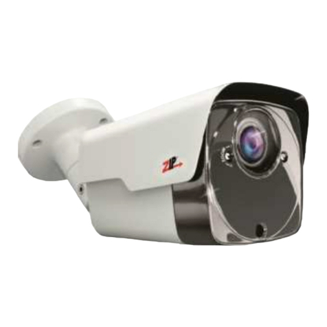
Vista VIP-B2MP27V135IRAUAL User manual

Vizion Bullet & Box Camera Range Quick Guide Ver 1.0 2022-12
IP Bullet & Box Camera Range

1
Before You Begin
Please read this guide before installing or operating the product. You
must have knowledge of CCTV, IT and electrical wiring and products.
Technical Support
If you still have questions after referring to the guide, or require more
information, please contact Vista Technical Support or use the QR code.
Vista Technical Support +44 (0) 118 912 5125
Norbain SD, Inspired, Easthampstead Road,
Bracknell, Berkshire RG12 1YQ
* WARNING: Improper use can cause severe bodily injury or
equipment damage.
This guide is intended for multiple product models. Illustrations and
descriptions, etc may vary from actual appearance.
Bullet
VIP-B2MP27V135IRAUAL
VIP-B5MP27V135IRAUAL
VIP-B8MP28V12IRAUAL
Bullet
VIP-B5MP28IRM
VIP-B8MP28IRMAUAL
Box
VIP-X2MPIRAUAL

2
1. Packing List
Please contact Norbain if any items are missing or damaged and note
contents will vary according to each camera model number.
➢Camera
➢Waterproofing items*1
➢Fixing Screws*2
➢Template*3
➢This guide
*1Including waterproofing components such as tape and sealing grommets.
*2Fixing screws and\or hex key according to camera model and requirement
*3Drilling template (except VIP-X2MPIRAUAL box camera)
2. Safety & Maintenance Instructions
•Use only correctly rated PSU\PoE delivery devices meeting
requirements shown in section titled 4. Power-up and Access
Camera”.
•Keep lens cover in place until installation completed - prevent damage.
•Ensure Ethernet/power cable lengths are within specification for
correct operation to avoid power or data loss.
•Ensure wall, ceiling and fixings are adequate to support the weight of
the camera and any bracket.
•Remove dust from the lens gently using oil-free brush or blower.
•Do not use organic solvents (benzene\alcohol) to clean bubbles etc.
•Where waterproofing accessories are provided, please ensure they
are fitted and in the correct order. Also fit weather plugs to unused DC
power sockets (below)
DC interface
Plug

3
3. Drilling and Mounting - All Cameras
Common to all cameras (except VIP-X2MPIRAUAL box camera) is the
template and drilling procedure. The square 4-hole template is shown
below as an example.
1. Hold supplied template to ceiling or wall and drill 6mm to 6.5mm
diameter holes to 30-mm depth.
2. Drill hole for fly lead cable to pass through.
3. Insert plastic anchors.
Now refer to the section for your specific camera model number.
VIP-B2MP27V135IRAUAL
VIP-B5MP27V135IRAUAL
VIP-B8MP28V12IRAUAL
Appearance and cable identification may vary between each model.
1. Alarm In\Out
2. Audio
3. Power (12 VDC)
4. Ethernet PoE interface
Use a Ø6-6.5 mm drill bit to drill 30 mm-
depth guide holes according to the
positions marked by the sticker.
DC12VIN DC
AUDIO
ALM
IP
Network

4
(Optional) Insert Micro SD Card
Insert SD card into slot for local storage
function (1) unscrew and remove cover
(right). (2) Insert card (below) then refit
cover.
Hot plugging is not recommended. Power off
first!
1. Loosen lock screw on camera bracket, connect required cables,
pass cables through cable clearance hole and fix camera to wall or
ceiling.
Locknut

5
2. Adjust camera direction, rotation and elevation (below) as required;
i. Slacken additional lock screw (1) at rear of camera.
ii. Slacken large locking collar (3) at the base.
3. Once correct position and field of view is achieved, tighten both lock
screws and large locking collar (3).
Note: Do not adjust camera direction by force with screw fully tightened!
Loosen the screw first.
Now refer to section titled 4. Power-up and Access Camera
1
1
2
3

6
VIP-B5MP28IRM
VIP-B8MP28IRMAUAL
Appearance and cable identification may vary between each model.
(Optional) Insert Micro SD Card
For cameras supporting Micro SD,
insert card after opening the
bottom cover of camera.
Do not hot plug SD cards -
power-down first!
1. Loosen large locking nut before fixing
camera to wall\ceiling –shown right.
(Optional)
Alarm / Audio
Network interface
12VDC Power
Micro SD card slot
Locknut

7
2. Pass cables through
cable clearance hole, connect
and fix camera to wall\ceiling
(below). Use waterproof tape if
provided.
3. Adjust camera position, rotation and elevation of view as
required (below), then lock into position by tightening
i. 2-lock screws (rear of camera & bracket elbow)
ii. Large locknut on camera base
Now refer to section titled 4. Power-up and Access Camera
Lead tapping screws through
the guide holes in the base
and fix them on the wall by
using a screwdriver.
Tighten the locknut.
Adjust the opening of the
universal joints as required.
Rotate the spherical hinge of
the camera to get the desired
monitoring direction.
1
2
3
2
1
3

8
VIP-X2MPIRAUAL –Box Camera
Appearance and cable identification may vary between each model.
Interface
Description
Grounding terminal
VIDEO OUT
BNC, outputs compound video signals
PWR
System status indicator
1000BASE-X
Unsupported
LINK/ACT
Ethernet link status indicator:
Steady on: Connection established.
Blinking: Data transmission.
ACT
Ethernet data transmission indicator
LINK
Ethernet network connection indicator
POE
Ethernet interface
ALM IN/OUT
Alarm input/output (refer to separate image)
RS485
RS485 serial port
UART/USB2.0
UART interface for UART and USB connection
LINE IN/OUT
Audio input/output
DC/AC
Power connector, DC 12V/AC 24V
RST
RST button
ABF
ABF button (for adjusting the back focus)
Note: Fine-tune the back focus to get clear images.
SD
Micro SD card slot (refer separate image)
Display device
Audio input
(sound pickup)
Audio output
(speaker)
Power adapter
Alarm output
(alarm lamp)
Alarm input
(voice activated switch)
Connect
vehicle detector

9
Alarm In\Out and 485
Refer to enlarged drawing of the
cameras alarm and 485 terminal
designation on the right for the
correct wiring of alarms etc.
P-plug Pin Designation
Refer below for pin designation.
Interface
Description
Iris control interface
Zoom control interface
1. ZOOM_A-
2. ZOOM_A+
3. ZOOM_B-
4. ZOOM_B+
Focus control interface
1. FOCUS_A-
2. FOCUS_A+
3. FOCUS _B-
4. FOCUS _B+
Zoom/Focus control interface
1. FOCUS+
2. FOCUS-
3. ZOOM+
4. ZOOM-
1
24
3
1
24
3
1
24
3

10
(Optional) Insert Micro SD Card
Insert SD card into slot for local storage
function –remove cover (right), then
insert card (below). Refit cover.
Hot plugging is not recommended.
Power off first!

11
Your box camera can be fitted to any compatible wall bracket or
external housing. Contact Vista Sales for possible options.
Below are example installations.
Once your box camera is fitted to your required bracket or housing
and all required cables have been connected, refer to the section
titled 4. Power-up and Access Camera
¼-20UNC

12
4. Power-up and Access Camera
After installing camera, connect either PoE Ethernet or Ethernet &
12VDC PSU with correct power rating for the camera. Refer to following
table for power details later in this guide.
DHCP is enabled as default. However, if no DHCP server is found,
camera will default as below;
Default IP address = 192.168.31.220
Default login = admin/123456
Connect suitable laptop to same LAN\VLAN and either set to DHCP or
an IP address in the range 192.168.31.x (but not 192.168.31.220!).
1. Either open Web browser on laptop and enter the camera's IP
address in the address bar, press Enter.
2. Or use the QR code provided
to download the Vizion
Discovery IP camera
discover tool onto the Laptop.
3. Follow on-screen instructions
to permit and instal any
required plug-in.
4. Login to camera with ID and password –use the default provided
earlier. Ensure you change to a strong password after first logging
in!

13
5. Refer to example [Network] menu below and make any static IP
address changes required.

14
Power Requirements per Camera Model
CAMERA MODEL
PoE
802.3af
PSU Minimum
VIP-B2MP27V135IRAUAL
8.5W
12VDC @ 1Amp
VIP-B5MP27V135IRAUAL
8.0W
12VDC @ 1Amp
VIP-B8MP28V12IRAUAL
10.5
12VDC @ 1Amp
VIP-B5MP28IRM
5.0
12VDC @ 1Amp
VIP-B8MP28IRMAUAL
10.5
12VDC @ 1Amp
VIP-X2MPIRAUAL
7.0W
12VDC @ 1Amp
This completes the procedure.
Carryout any individual camera settings required for your specific
installation before adding the camera to you NVR recorder. Refer to the
provided QR code for additional manuals and resources.
Factory Defaulting
Where the camera is provided with a hardware reset button (indicated in
each camera model section previously in this guide) simply use a pin to
press and hold the Reset button for 15-seconds to restore factory default
settings. This operation must be performed within 10-minutes after the
device is powered u, otherwise the reset will be ignored.

15
Where applicable, a Declaration of Conformity in accordance with
Directives 2014/30/EU (EMC), 2014/35/EU (LVD),and 2015/863/EU
RoHS(3) has been made and we declare the product compliant.
Where applicable, the requirements of the European law on the Restriction
of Hazardous Substances (RoHS) directive: 2015/863/EU have been met
and the product is without the hazardous substances cited in the directive.
Our CE EU-Authorised Representative: Comply Express Unipessoal
LDA, StartUp Madeira - EV141, Campus da Penteada, 9020-105
Funchal, Madeira, Portugal”
Symbolizes that within the European Union the product must be collected
separately at the product end-of-life. Do not dispose of these products as
unsorted municipal waste.
A UK Declaration of Conformity in accordance with GB UKCA standards
has been made. The manufacturer declares that the product supplied with
this document is compliant with the provisions of the Electromagnetic
Compatibility Regulations 016, and where applicable, the Electrical
Equipment (Safety) Regulations 2016 Directives.
WARNING
This is a Class A product. In a domestic environment this product may cause radio
interference in which case the user may be required to take adequate measures.
This manual suits for next models
5
Table of contents
Other Vista Digital Camera manuals

Vista
Vista VS50 User manual

Vista
Vista VPC9030 User manual
Vista
Vista VIP-T5MP27V135IRM User manual
Vista
Vista VZM22INT600 User manual
Vista
Vista VFDA28V12CM960H24 User manual

Vista
Vista Optio OPA Camera User manual

Vista
Vista VPC580/4CM User manual

Vista
Vista Eclipse2 User manual
Vista
Vista NCL735e User manual
Vista
Vista VBC13MC User manual
