1625 Surveyor Avenue • Simi Valley, CA 93063 • (805) 527-0987 • (800) 766-VISTA (8478)
COVER LOCKIN
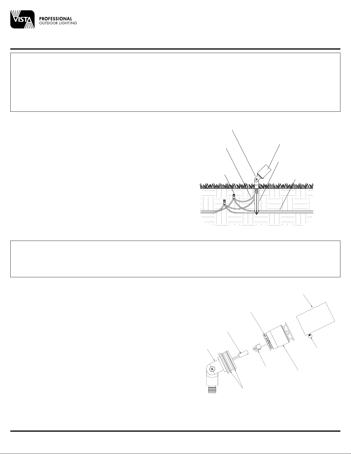
THUMB SCREW
FIXTURE COVER
FIELD REPLACEABLE
LED ENGINE
LOCK RING
MALE
CONNECTOR
FEMALE
CONNECTOR
SILICONE O-RING
FIXTURE BASE AND
KNUCKLE ASSEMBLY
The operating voltage range for this LED luminaire is 6 - 15 volt AC. The Vista electronic driver ensures the LED operates at the intended lumen output while
receiving voltage as low as 6 volts, and as high as 15 VAC, resulting in a balanced lumen output from the first fixture to the last. Eliminating the dimness issues
often attributed to voltage drop.
Note: Operating voltage range for LED luminaries will vary depending on model, style and total number of LEDs. To help determine the operating
voltage range for each Vista luminaire, always consult factory’s specification sheet and/or installation instructions before installation.
INSTALLATION INSTRUCTIONS
Vista Professional Outdoor Lighting reserves the right to modify the design and/or construction of the xture shown without further notication.
2120 04.16
Housing
d
36” Pigtail
Adjustable Knuckle
Main Supply Cable
Ground Stake
FOR USE ONLY WITH LOW VOLTAGE LANDSCAPE POWER UNITS THAT DO NOT EXCEED 25 AMPS, 15 VOLT MAXIMUM.
WARNING: Luminaires must be installed in accordance with the National Electrical Code (NEC) and local codes. Failure to do so will void the warranty and may
result in serious injury and/or damage to the luminaire.
SAFETY WARNING: Luminaire can become very hot depending on lamp wattage used. Lens and metal around lamp can become hot enough to blister hands.
Particular care should be taken not to locate luminaires where small children can reach them if high wattage lamps are used.
LUMINAIRES ARE NOT TO BE INSTALLED WITHIN 10 FT (3.05M) OF A POOL OR SPA. SECONDARY CABLE IS NOT TO BE BURIED MORE THAN 6”.
WHEN USING MULTIPLE LUMINAIRES, LOAD IS NOT TO EXCEED TOTAL WATTS OF TRANSFORMER RATING. DO NOT USE EXTENSION CORDS ON
POWER UNITS.
NOTE: Always use UL recognized wire connectors for connections.
NOTE: Save these instructions for future reference; leave with property owner/manager.
LUMINAIRE MOUNTING:
1. To prevent electrical shock, disconnect transformer from electrical supply
before installation or service.
2. Run wire pigtail from luminaire through the mounting hole in top of ground
stake.
3. Thread luminaire into threaded hole in ground stake.
4. Place stake in desired position and insert into ground until flange of stake is
flush to grade.
5. Strip the (2) leads from the luminaire pigtail wire. Using the two (2) silicone
filled safety connectors (provided), connect the leads from the luminaire to the
main supply cable leads.
NOTE: Luminaires are supplied with 36” of 18-2 cable pigtail for secure
connection to the main supply cable. The wire is to be protected by routing in
close proximity to the luminaire. The wiring should be buried a maximum depth
of 6 inches (15.2 cm) in order to connect to the main supply cable.
6. Aim luminaire to desired angle. Lock into place by tightening Phillips screw
in adjustable knuckle.
NOTE: Avoid aiming fixture directly upward. Whenever possible, set at angle
to prevent rain or irrigation water from settling on lens.
LED ENGINE INSTALLATION/REPLACEMENT:
1. To prevent electrical shock, disconnect transformer from electrical supply
before service.
2. Loosen shroud locking screw.
3. Remove shroud to expose field replaceable LED engine.
4. Remove stainless steel locking/expansion ring.
5. Pull up LED engine assembly out of fixture body.
6. Disconnect Connector Assembly.
7. Connect new Field Replaceable LED Engine to Connector Assembly.
8. Re-install LED base assembly onto fixture body.
9. Re-install stainless steel locking/expansion ring.
10. Re-install shroud and locking screw.
SEE REVERSE
FOR INCANDESCENT Up & Accent Lights
Landscape Series
2120


