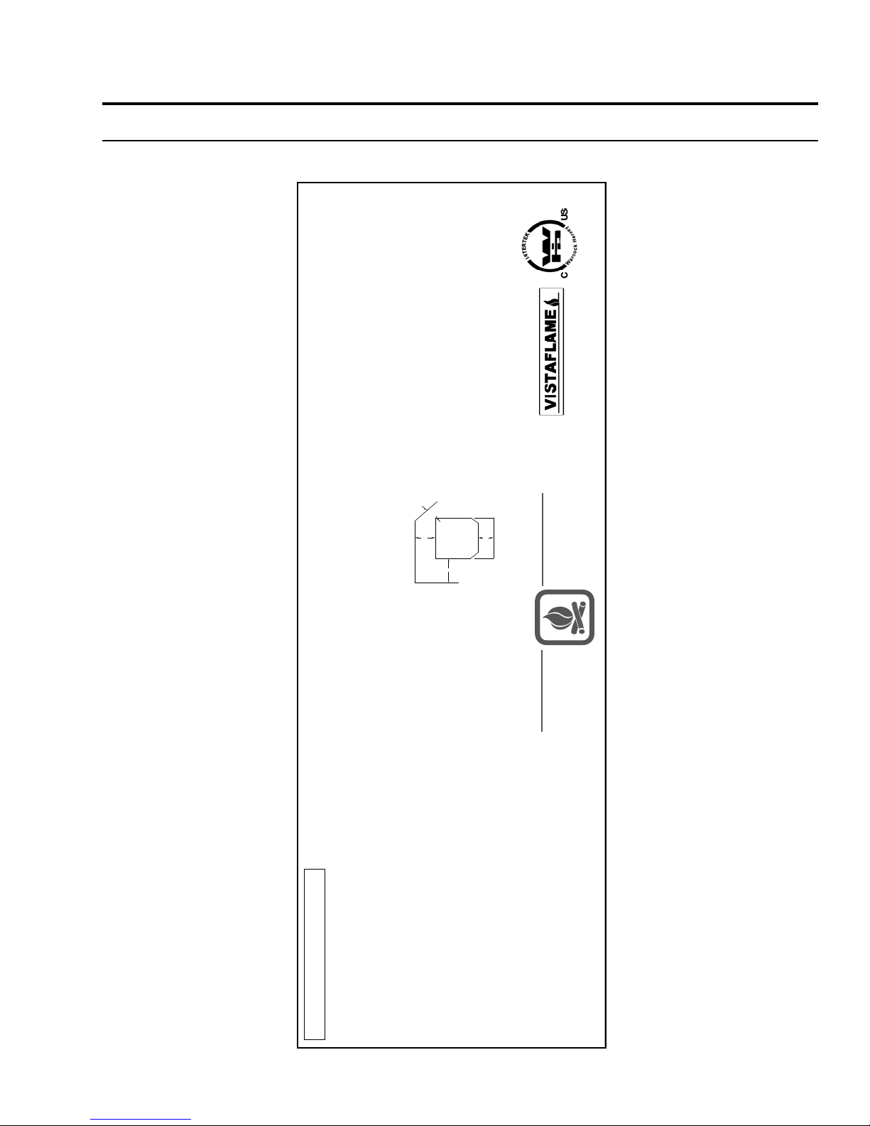
Certified for use in Canada & USA
Certifié pour installation au
Canada et aux Etats-Unis.
Model / Modèle: VF-55
Listed Room Heater, Pelletized Fuel Type (Appareil de chauffage à granules certifié)
Suitable For Mobile Home Installation (Accepté pour l'installation dans une maison mobile, test)
Tested to (Testée selon): ASTM 1509-04. US Environmental Protection Agency, certified to comply July 1, 1990,
particulate emission standards. (États-Unis Environnemental Protection Agence, a certifié pour conformer au Juillet
1, 1990, les normes de particules d'émission.)
This pellet appliance has been tested and listed for use in manufactured homes in accordance with Oregon
Administrative rules 814-23-900 through 814-23-909.Install and use only in accordance with the manufacturer's
installation and operating instructions. Contact local building or fire officials about restrictions and installation
inspection in your area. Do not connect this unit to a chimney flue serving another appliance. See local building code
and manufacturer's instructions for precautions required for passing a chimney through a combustible wall or ceiling.
ELECTRICAL RATING: 120 Volts, 60Hz, 4.2 Amps. Route Cord Away From Heater.
For use with pelletized solid fuels - wood, corn, wheat, & barley only. Operate only with viewing door and ash removal
door closed. Only replace glass with ceramic glass. Components required for installation 3in/75mm or 4in/100mm
listed PL vent complete with components.
Cet appareil a été testé et certifié pour utilisation dans les maisons mobiles en accord avec les "Règles
Administratives de l'Oregon 814-23-900 à 814-23-909". Installez et utilisez cet appareil seulement selon les
instructions d'installation et d'opération du fabricant. Contactez les autorités locales de votre quartier concernant les
restrictions et les inspections d'installation. Consultez les codes de bâtiment locaux et les instructions du fabricant
pour les précautions à prendre lorsque une cheminée doit être installée au travers un mur ou un plafond combustible.
CLASSEMENT ÉLECTRIQUE : 120 Volts, 60 Hz, 4.2 Amps. Placez le câble électrique loin de la chaleur.
WH-VF55-
MANUFACTURED BY /
FABRIQUE PAR
:
SHERWOOD INDUSTRIES LTD.
VICTORIA BC CANADA
DATE OF MANUFACTURE /
DATE DE FABRICATION:
J F M A M J J A S O N D 2009 2010 2011
CAUTION:
HOT WHILE IN OPERATION. DO
NOT TOUCH. KEEP CHILDREN,
CLOTHING AND FURNITURE
AWAY. CONTACT MAY CAUSE
BURNS. SEE NAMEPLATE AND
INSTRUCTIONS.
ATTENTION:
L'APPAREIL EST CHAUD LORSQU'IL
FONCTIONNE. NE PAS TOUCHER. GARDER LES ENFANTS,
LES VÊTEMENTS ET LES MEUBLES ÉLOIGNÉS DE
L'APPAREIL EN MARCHE. UN CONTACT AVEC CELUI-CI
POURRAIT RÉSULTER EN DES BRÛLURES. VEUILLEZ
VOIR LA PLAQUE DU FABRICANT ET LES INSTRUCTIONS.
DO NOT REMOVE THIS LABEL /
NE RETIREZ PAS CETTE ÉTIQUETTE
Floor Protection
A
BC
D
Backwall
Sidewall
C-11960
Installed as a freestanding stove - conventional or mobile home -
Model FS. Minimum Clearances to Combustible Material / Espace
de dégagement requis pour le modèle FS, qu'il soit encastré, sur
pied ou dans une maison mobile:
Sidewall to Unit / Du mur de côté à l'appareil: A 12 in / 305 mm
Backwall to Unit / Du mur de derrière à l'appareil: B 3 in. / 76 mm
Corner to Unit / Du coin à l'appareil: C 3 in. / 76 mm
D - The unit must be installed with a minimum of 6" (152 mm) of
floor protection in front of and to the sides of the door opening.
Serial No. / No. De Serié:
To Start Stove: Select fuel type mode; PREMIUM PELLETS for superior quality pellet fuel, REGULAR PELLETS for all
grades of wood pellets & MULTIFUEL for all other fuels. Press the ON / OFF button. A small handful of pellets in the
burn pot liner will speed up ignition.
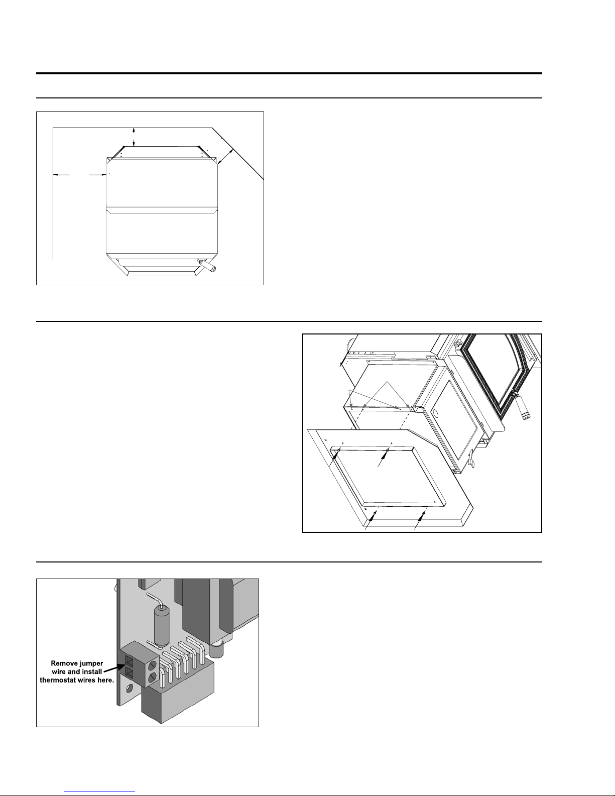
To Operate Stove: MANUAL MODE: When a fire has been established the stove settings are adjustable. / HIGH/LOW
MODE: (Requires a thermostat) When the thermostat calls for heat the stove settings are adjustable. When the
thermostat contacts open, the HEAT LEVEL and Fans will drop down to the LOW setting until the thermostat contacts
close again. / AUTO/OFF MODE: (Requires a thermostat) When the thermostat contacts close, the unit will light
automatically. Once up to temperature the stove settings are adjustable. When the thermostat contacts open, the stove
will drop down to the LOW settings for 30 minutes. If within the 30 min the thermostat contacts close, the HEAT LEVEL
will return to previous MANUAL setting or if the thermostat contacts remain open the stove begin its shutdown routine
and it will restart when the thermostat closes.
To Turn Off Stove: MANUAL and HI / LOW mode: Press the ON / OFF button
AUTO / OFF mode: Turn the thermostat down or off.
Pour démarrer le poêle: Choisir le mode pour le carburant ; PREMIUM PELLETS pour le carburant de boulette de
qualité de superior, REGULAR PELLET pour tous degrés de boulettes de bois & MULTIFUEL pour tous autres
carburants. Appuyer sur le bouton "ON/OFF". Une petite poignée de boulettes dans le pot de brûlure hâtera l'allumage.
Pour faire fonctionner le poêle : MODE MANUEL : Lorsque le feu est bien établi, les réglages peuvent être ajustés. /
MODE "HIGH/LOW" : (Nécessite un thermostat) Lorsque le thermostat requière de la chaleur, les réglages peuvent
être ajustés. Lorsque les contacts du thermostat ouvrent, le réglage du niveau de chaleur et les ventilateurs
s'ajusteront au réglage " bas " jusqu'à ce que les contacts du thermostat se referment. / MODE "AUTO/OFF" :
(Nécessite un thermostat) Lorsque les contacts du thermostat ferment, le poêle s'allumera automatiquement. Lorsque
la température adéquate est atteinte, les réglages peuvent être ajustés. Lorsque les contacts du thermostat ouvrent, le
poêle s'ajustera aux réglages "LOW" pendant 30 minutes. Si les contacts du thermostat sont fermés pendant ces 30
minutes, le réglage de niveau de chaleur retournera en réglages "MANUEL" ou si les contacts du thermostat restent
ouverts, le poêle entamera le processus d'arrêt et il vouloir redémarrer lorsque les contacts du thermostat refermer.
Pour éteindre le poêle : MODE MANUEL ET " HIGH/LOW " : Appuyer sur le bouton "ON/OFF".
MODE "AUTO / OFF" : Régler le thermostat à la baisse ou éteignez le.
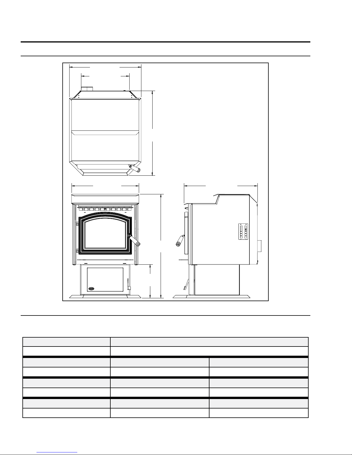
The pedestal base can be adjusted to
the forward position to satisfy this
requirement. The unit can be installed
on a hard, stable combustible
surface.
Utilisation avec granules - le bois, le maïs, le blé, & l'orge seulement. Utiliser seulement lorsque les
portes avants et la porte du réceptacle de cendre sont fermées. Si une ou des vitres devaient être
remplacées, utilisez seulement du verre céramique. Les composantes requises pour l'installation
sont un évent PL certifié de 3in/75mm or 4in/100mm avec ses composantes.
(D - L'unité doit être installée avec
protection de plancher devant et au
bord de la porte ouvrant avec au moins
6" (152 mm). La base de piédestal peut
être adaptée à la position à satisfaire
cette condition. L'unité peut être
installée sur un dur, la surface
combustible stable.)
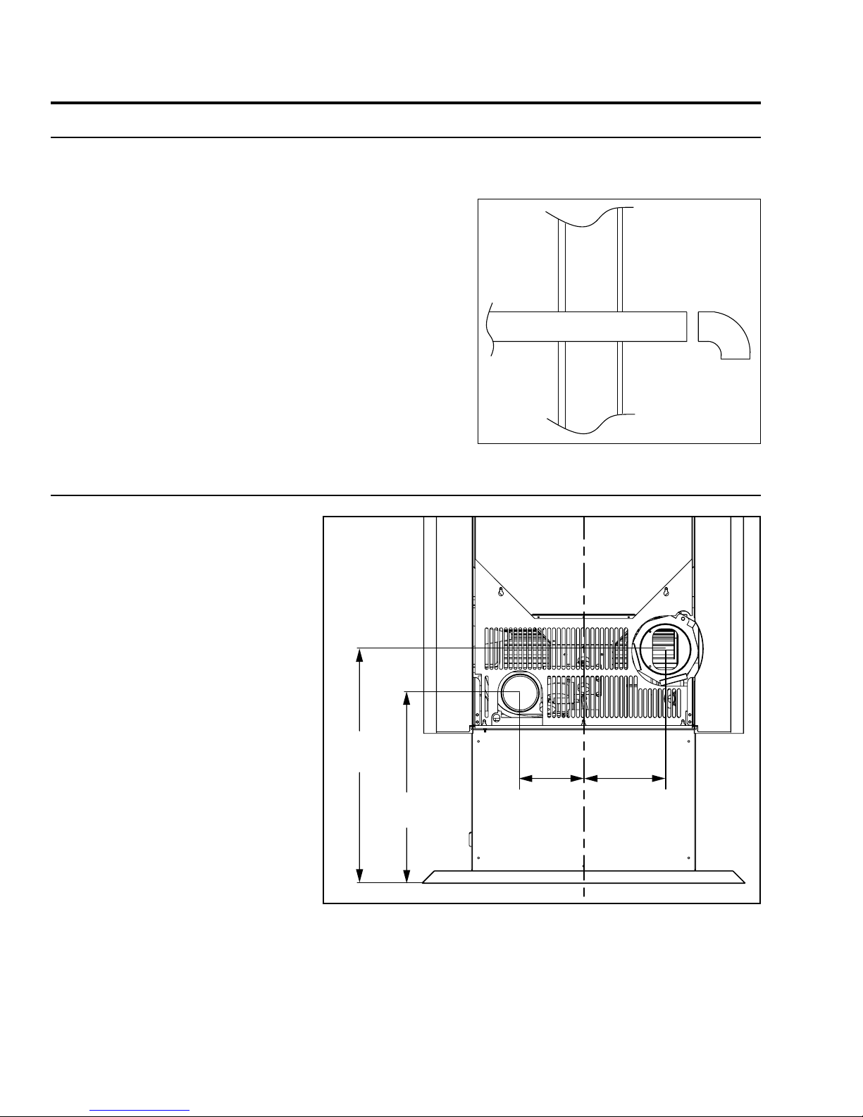
Figure 1: VF-55-FS Rating Label.