VISTEK V1640A Owner's manual

29 October, 2003 v1640Aom_b.doc / B Page 1 of 11
V1640A
SDI VIDEO SYNCHRONISER
INSTALLATION and OPERATION
© Vistek Electronics Ltd
Filename: v1640om_b.doc
Issue B
October, 03
VISTEK Electronics Ltd
Wessex Rd
Bourne End
Buckinghamshire, SL8 5DT
ENGLAND
Tel. +44 1628 531221
Fax. +44 1628 530980

1 March, 2005 v1640Aom_b.doc / B Page 2 of 11
SDI VIDEO SYNCHRONISER
INSTALLATION AND OPERATION
1. DESCRIPTION
The V1640A SDI Video Synchroniser is a full broadcast specification Frame Synchroniser forming
part of the Vistek V1600 range of interface products. It is a 3U high module which can be fitted to
either the 1U V1601 or 3U V1603 chassis from which it receives its power. It replaces the existing
V1640 module with which it is fully compatible. The main improvements over its predecessor is that
local adjustment of the timing offsets is possible without removing the unit from the rack, and full
control over DART has been implemented. There are some other minor operational improvements
which are detailed later in this manual. Mechanically the unit has been improved since it is now built
on a single PCB, rather than using two.
When fitted in either the V1601 or the V1603 racks passive rear modules are required to interface to
the outside world. Different rear modules are required for the two chassis. The rear modules are
common to many other Vistek video modules.
The unit automatically operates in either 625/50 or 525/60 formats depending on the input signal.
Normally the Black and Burst reference will be of the same standard, but in the case of it being
different the unit will operate according to the SDI input and set itself to minimum delay. This has
been implemented for use in those areas where the input signal may originate in either standard,
and will be either synchronised or passed through a Standards Converter which will in itself
synchronise the signal.
There is a choice of action in the event of signal loss. The unit can either Freeze or cut to Black.
Provided a reference is connected the output timing is not affected by the loss of the input signal .
When operating in with 625/50 signals the unit works as a Line Synchroniser. This means that it
can handle cuts on the input signal with less picture disturbance than usual, provided the cut is done
on one of the designated switching lines, 6 or 7. The relative timing of the two signals on each side
of the cut should be within approximately 20 lines.
A TTL output is available which indicates the amount of delay being applied to the signal. This can
be used in a suitable tracking audio delay (such as the Vistek V1639) to ensure that video and audio
can stay timed correctly.
The front panel enables direct control of most functions within the unit. It is also used to switch
control from the front panel to the remote DART system. The unit contains non-volatile memory so
that when any parameters are set up locally they are still available after a power-down. Since the
timing offsets are often so important to an installation, an internal DIL switch is available to lock
them out. This prevents ‘accidental’ adjustments of the timing. Adjustment is always available over
DART, since the control system has its own built in safeguards.
The user may selectively pass or blank non-active video signals. Separate control is available over
the Vertical Blanking data, such as Teletext or Insertion Test Signals, and ancillary data, such as
embedded digital audio.
When operating in 525 mode later versions have the ability to selectively blank Line 21 on either
field to remove Closed Caption information. This can only be donelocally on a DIL switch.
The unit is fully controllable over the DART remote control system.
The output of the unit has full EDH signals applied, but there is no EDH detection on the input.
1 March, 2005 v1640Aom_b.doc / B Page 3 of 11
2. INSTALLATION
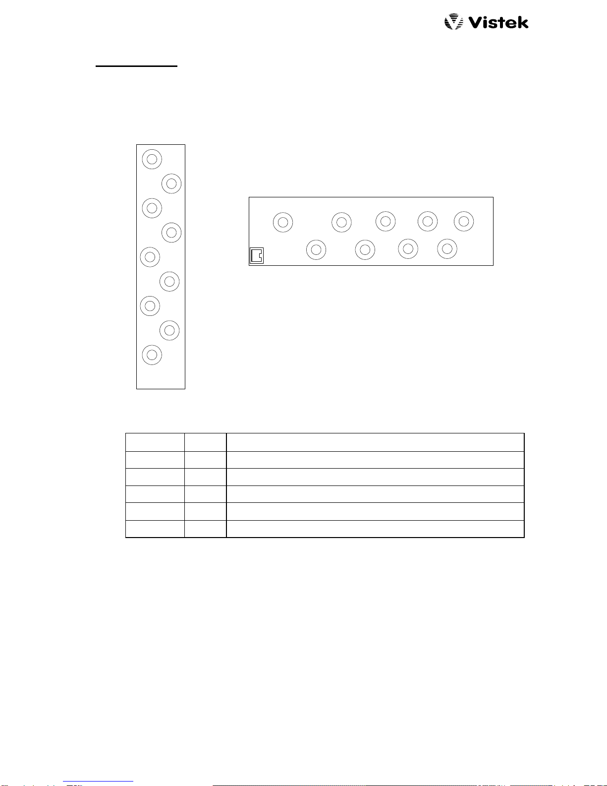
2.1 REAR PANEL
Two rear panels are available depending on the type of chassis into which the unit is fitted:
3U (V1603)
SDI
SDI1
SDI2
SDI3
VIDEO
REF
DELAY
1U (V1601)
SDI
IN
SDI1
SDI2
SDI3
VID. REF
DART
DELAY
2.2 REAR PANEL CONNECTIONS
SIGNAL CONN DESCRIPTION
SDI IN BNC SDI Video Input
SDI 1, 2, 3 BNC 3 off SDI Video Outputs
DELAY BNC TTL Delay Pulse
VID. REF BNC Video Reference Input. An internal switch enables 75Ωtermination.
DART RJ45 DARTNET connection. Only used in on position in 1U rack.
2.3 POWER CONSUMPTION
The V1640A power consumption is 6.5W
2.4 INSERTION DELAY
The insertion delay is, of course, variable over a frame. If the input and reference frame rates are
different then the delay will vary. At some stage there will be a frame drop or a frame repeat and
just before or just after there will be a point of minimum insertion delay. There is hysteresis in the
frame discontinuity, to avoid rapid toggling, so the minimum delay depends on the drift direction:
Minimum Delay (Increasing): 1.65µs
Minimum Delay (Decreasing): 1.05µs
The minimum delay, as set from the front panel or through DART, is 1.7µs.
1 March, 2005 v1640Aom_b.doc / B Page 4 of 11
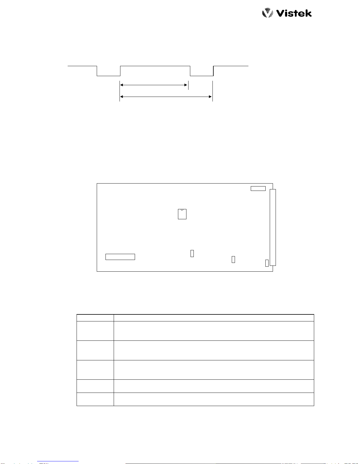
2.5 DELAY O/P
The Delay O/P signal is a TTL levels rectangular wave. The period is the same as the frame rate
(40ms for 625/50 and 33.3ms for 252/60) but the mark-space ratio varies according to the amount of
delay.
Frame
Delay
The minimum pulse width, either positive or negative, is 37ns.
2.6 INTERNAL HARDWARE
2.6.1 MAIN BOARD
FRONT PANEL
REAR CONNECTOR
PROM
DIL SWITCH
LK1
SW5
U15
FS1
18
VR1
VR2
The significant items on the main board are described here:
FS 1 Input power fuse, 3A.
SW 5 Internal configuration switches, S1 at the left. See section 3.11 for details.
Note that each switch is UP or DOWN. Ignore the ‘OFF; indication on the
switch block.
U15 The 8 pin DIL PROM that contains the firmware for the programmable device.
In the event of upgrades in the field it is most likely that this is the device that
will need to be changed.
LK 1 Enables termination of the video reference:
UP = Open
DOWN = Terminated
VR 1 Factory adjustment for reference standard select.
Adjust for 18ms on TP 49
VR 2 Factory adjustment for oscillator centre frequency.
Adjust for 27MHz on TP 39.

1 March, 2005 v1640Aom_b.doc / B Page 5 of 11
3. OPERATION
3.1 FRONT PANEL
REM +V
Local
Rem
V1640A
SDI Frame
Synchroniser
DART Control Access and Power indicators
REMOTE / LOCAL control selection
Input Format
I/P
Ref
525 625
H Adjust
V Adjust
FL Mode
Input
Min Delay
ANC & VI
Select
Normal
+
Reference Format
Adjust Horizontal Offset
Adjust vertical Offset
Set Input Fail Mode
Select Input Signal
Set Minimum Delay
Control VBI and Ancillary data handling
Control Select Button
'UP' Button
'DOWN' Button
Status LEDs
3.2 CONTROL
The V1640A can be controlled from either the front panel, shown above, or through the DART
remote control Network. If DART is used then any DART controller, with knowledge of the V1640A
can be used. Vistek can provide either the V1605 1U control panel or VIEWFIND which is a PC
based universal control system. Any DART controller can be used, provided it has ‘knowledge’ of
the V1640A.
The control source, Local or Remote, is selected by the toggle switch on the front panel. The REM
LED does not indicate the selection of remote control, but ‘blips’ to show access by the Rack
Controller, if fitted. Only the position of the toggle switch indicates that remote control has been
selected.
When in Local control the front panel allows the user to set up all the parameters, and can show
how most of them are set. All the status LEDs on the front panel are active for Local or Remote
control so that they always show the operating conditions.
When under Remote Control the Parameter Select sequence is still active, although it is not
possible to change anything from the Local panel. This means that the user can still monitor the
state of the unit while under Remote Control.

1 March, 2005 v1640Aom_b.doc / B Page 6 of 11
3.3 INDICATIONS
3.3.1 POWER
The power LED, marked +V, indicates that the 5V VCC power rail is present on the board. This
shows not only that power has been applied to the rear, but also that the on board regulator is
functioning.
There is a fuse on the unit in series with the power input, and if this has ‘blown’ then the +V LED will
be OFF, as will the other LEDs.
There are other power rails on the unit (3.3V and ±5V) which are generated from the VCC, rather
than directly from the board supply. The +V LED may still be on even if these supplies have failed.
3.3.2 REM
This LED indicates that the unit is being accessed remotely by the DART system. It does NOT
reflect the position of the REM/LOC switch. The LED is not permanently ON, but blinks occasionally
when data is actually being transferred to or from the unit.
3.3.3 INPUT PRESENCE and FORMAT
This pair of LEDs indicate the presence and format of the input signal. The unit detects whether the
input is D1 525/60 or D1 625/50 and lights one of the LEDs accordingly. If there is no input signal
then neither LED is ON. This is the only panel indication of input signal fail.
3.3.4 REFERENCE PRESENCE and FORMAT
This pair of LEDs indicate the presence and format of the analogue reference signal. The unit
detects whether the input is 525/60 or 625/50 and lights one of the LEDs accordingly. If there is no
reference then neither LED is ON. This is the only panel indication of there being no reference.
It is quite possible to operate the unit with opposite formats on the input and reference. In this case
the unit will default to the input signal format, ignoring the reference completely, and set itself to
minimum insertion delay.
3.3.5 PARAMETERS
These LEDs indicate that one of the parameters has been selected for adjustment. Pressing the
SELECT button repeatedly selects each parameter in sequence. Only when a parameter has been
selected can it be adjusted by the sand tbuttons.
Note that there is one sequential position when no parameter is selected. This is the ‘idle’ state
where nothing can be affected by accident.
There is a time-out of either 68 secs (525/60) or 82 secs (625/50) so that if no adjustment is made
to a parameter within that time then it will return automatically to the ‘idle’ state. (Early units had a
shorter time-out of 34 and 41 seconds.)
Later sections discuss each of these adjustment parameters in more detail.
Under certain conditions it may not be possible to select the timing adjustment parameters; the
details are in section 3.4.
1 March, 2005 v1640Aom_b.doc / B Page 7 of 11
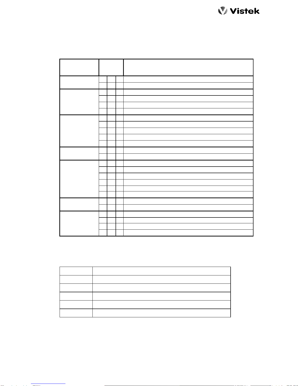
3.3.6 STATUS LEDs
These three LEDs give a guide as to the state of the variable parameters. It is clearly not possible
to give a full representation using only three LEDs but the following table shows how most of the
important information is conveyed.
LEDs
PARAMETER + N - DESCRIPTION
none (Idle) lWlNormal
WlWMinimum Delay is selected
WWlDelay >1 Field, Outside Hysteresis zone
WllDelay >1 Field, In Hysteresis zone
H Adjust llWDelay <1 Field, In Hysteresis zone
lWWDelay <1 Field, Outside Hysteresis zone
WllVertical Offset = +127 lines
WWl0 < Vertical Offset < +127 lines
V Adjust lWlZero offset
lWW-128 lines < Vertical Offset < 0
llWVertical Offset = -128 lines
FL Mode lWlFreeze field on Input Fail
WlWBlack on Input Fail
WlWFreeze Frame
llWFreeze on Field 2
Input WllFreeze on Field 1
lWlSDI Input signal
lllBlack
WlWInternal 100% Colour Bars (not broadcast quality)
Min Del lWlMinimum Delay OFF
WlWMinimum Delay SET
lWWPass VBI, Blank Ancillary
Anc & VI lllBlank Both
WlWPass Both
WllBlank VBI Pass Ancillary
3.4 LOCAL PARAMETER SELECTION
This table is a list of the local parameters that can be adjusted.
H Adjust Horizontal Offset Adjustment
V Adjust Vertical Offset Adjustment
FL Mode Signal Fail Mode
Input Input Source
Min Delay Minimum Delay
ANC & VI Ancillary Data and Vertical Interval data
There are two conditions during which it is not possible to select H Adjust and V Adjust. If
Min Delay is active then the output timing is not adjustable from the front panel, and there is a non-
standard display in the idle state. Secondly if the Lock-Adj DIL switch is set (S2 on SW 5) then
they will not be selected; see section 3.11.2. In either case the parameter selection will pass
straight from Idle to FL Mode.

1 March, 2005 v1640Aom_b.doc / B Page 8 of 11
3.5 SETTINGS MEMORY
All local parameter values are stored in a non-volatile memory, so they do not have to be set up
each time the unit is powered. When a value is changed it is only stored into the memory when the
parameter selection is changed. This means that if you alter a parameter and then remove the
power (or remove the unit from the chassis) before pressing SELECT or allowing the time-out to
happen, then the new value will not have been stored.
3.6 OFFSET ADJUSTMENTS
The output timing can be offset from the reference using two parameters. The first allows horizontal
adjustment over a full line, while the second allows vertical adjustment over -128 to +127 lines. The
reference will be either the external analogue video signal, or the D1 input itself. This means the
unit may be used as delay line.
The status LEDs give some indication during horizontal adjustment as shown in section 3.3.6, and
during vertical adjustment show which direction the offset is, and whether it is at its maximum.
If the unit has Min Delay or Lock-Adj set then the timings cannot be adjusted.
3.7 I/P FAIL MODES
The V1640A has sophisticated monitoring on the SDI input, so it handles intermittent signals in a
‘user-friendly’ manner. Minor disturbances to the TRS data (roughly equivalent to the Sync pulses
in an analogue video signal) cause short freezes of the data. However if the input fails completely,
which is defined by either a loss of the input 270MHz or a sequence of erroneous TRS signal then
the unit goes into its Fail mode.
This Fail mode can be either a freeze to the last ‘good’ field that has been stored, or a cut to black,
as set on the FL Mode parameter. The normal operation is to freeze the picture, but sometimes this
can be a disadvantage when installing or setting up a system when the user might actually want to
know that the input has failed.
3.8 INPUT
Although titled Input, this parameter selects the signal source that is passed out of the V1640A.
There are five options as follows:
Freeze Frame
Freeze Field 2
Freeze Field 1
SDI Input
Digitally Generated Black
100% Colour Bars
Any of the Freeze functions actually cause a whole frame to be frozen, and if a Field Freeze is
chosen then the output processing ensures that only one of the fields is displayed. Under these
conditions a single input field will be displayed on both output fields. This will reduce any blurr
caused by motion at the point of freezing, but the vertical resolution will also be reduced.
Since the whole frame is frozen all three freeze options are available without having to re-freeze the
input signal.
The Digital Black and Colour Bars are generated on the output side of the V1640A but the input
processing and front panel indications are still active. The Colour Bars are so-called ‘hard’ bars in
that they have no transition edge shaping. This means that they contain very high frequencies and
will produce ringing on all transition after a DAC.
1 March, 2005 v1640Aom_b.doc / B Page 9 of 11
3.9 MINIMUM DELAY
The unit can be set into a Minimum Delay mode without having to actually adjust the timings, which
would lose their settings. The actual minimum delay for both formats is as defined above in
section 2.4. The main advantage of the Minimum Delay is to ignore the reference even though it is
still connected.
Because the timing adjustments have no effect when Min Del is active, it is not possible to select
them as a parameter. It is also indicated on the Idle menu by both the +and -LEDs being on.
3.10 ANC. DATA AND VBI
In some installations it may be desirable to blank either the Vertical Blanking Interval data and/or the
Ancillary data. The VBI often contains Teletext or Insertion Test signals which occupy the active
video portions of the vertical interval; they may be passed through the V1640A.
An SDI signal may contain Ancillary data in the horizontal blanking between the EAV and SAV TRS
signals. Often this data is embedded digital audio, and should be removed from the V1640A output.
This is because the any Frame Synchroniser, including the V1640A, can introduce discontinuities in
the frame sequence when the input and reference signals are not synchronous which will cause a
major disturbance to digital audio.
The ‘normal’ setting for the V1640A is to pass the VBI data, but to blank the Ancillary data.
If the Ancillary data is set to blank then ALL information between the EAV and SAV is removed, not
just audio data.
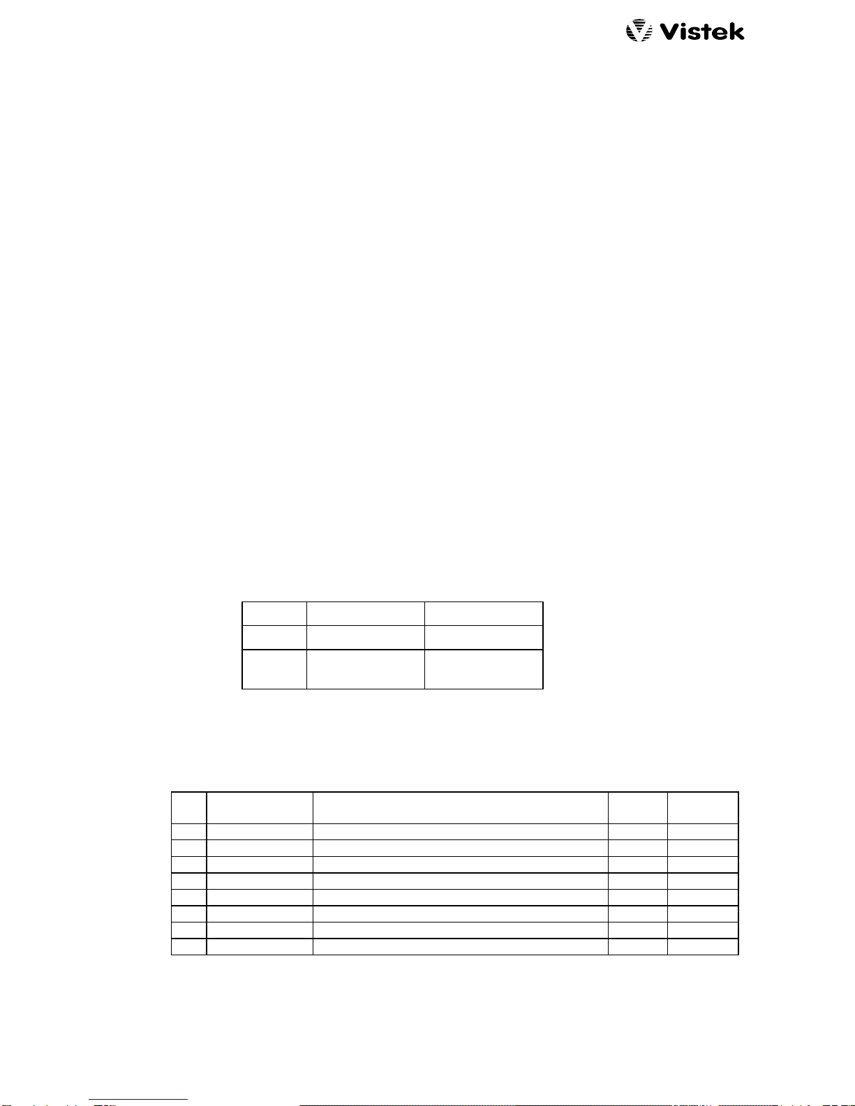
If the VBI is set to be blanked then the active portions of the following lines are removed depending
on the standard:
625/50 525/60
Field 1 9 - 22 12 - 20
Field 2 321 - 335 274 - 282
(11 - 19)
3.11 INTERNAL SETTINGS
An eight way DIL switch on the PCB (SW 5) is used to set up some internal parameters as shown
here:
S Title Description UP Down
(= OFF)
1 DEF STD Default Standard (used when no I/P and no Ref) 625/50 525/60
2 LOCK ADJ Lock local control of timing adjustments Free LOCKED
3 REF FL MODE Reference Fail Mode Norm Min delay
4 Field 1 Line 21 Selectively blank this line in 525 mode only Pass Blank
5 Field 2 Line 21 Selectively blank this line in 525 mode only Pass Blank
6 reserved
7 reserved
8 reserved
For normal operation all switches should be set to UP.

1 March, 2005 v1640Aom_b.doc / B Page 10 of 11
3.11.1 DEFAULT STANDARD
This switch sets the operating standard when there is no input or reference. This can be useful
during system installation when an output SDI signal may be needed of the correct format with no
input or reference. For example the non broadcast quality colour bars may be used.
The unit does ‘remember’ which standard it is operating on even after the SDI input and reference
have been removed, so this setting is only really used when the unit is powered up without any
signals.
3.11.2 ADJUSTMENT LOCK OUT
To avoid accidental adjustment of the timing values this switch should be set down. Make sure that
the values you want are properly stored in the non-volatile memory before removing the unit from
the chassis (see section 3.5).
When the Adjustment Lockout is active it is not possible to select the H Adjust and V Adjust
positions.
The DART remote control system can still change the timing values independently of this switch
setting.
3.11.3 REFERENCE FAIL MODE
This switch changes the output when the reference fails. Normally the unit will switch its locking
reference to the SDI input signal (if present) and continue to provide an output and the adjustment
offsets are still applied. If this switch is set DOWN then the unit will go into minimum delay and the
adjustment parameters will have no effect.
In either case if there is no input either, when the reference fails, then the output will free-run from its
internal crystal oscillator. The unit will operate in the same standard that was last applied.
3.12 EDH
The unit contains an EDH (Error Detection and Handling) chip on its output stages. This is
permanently set to generate mode, so it produces correct EDH data whatever the state of the input
signal.
1 March, 2005 v1640Aom_b.doc / B Page 11 of 11
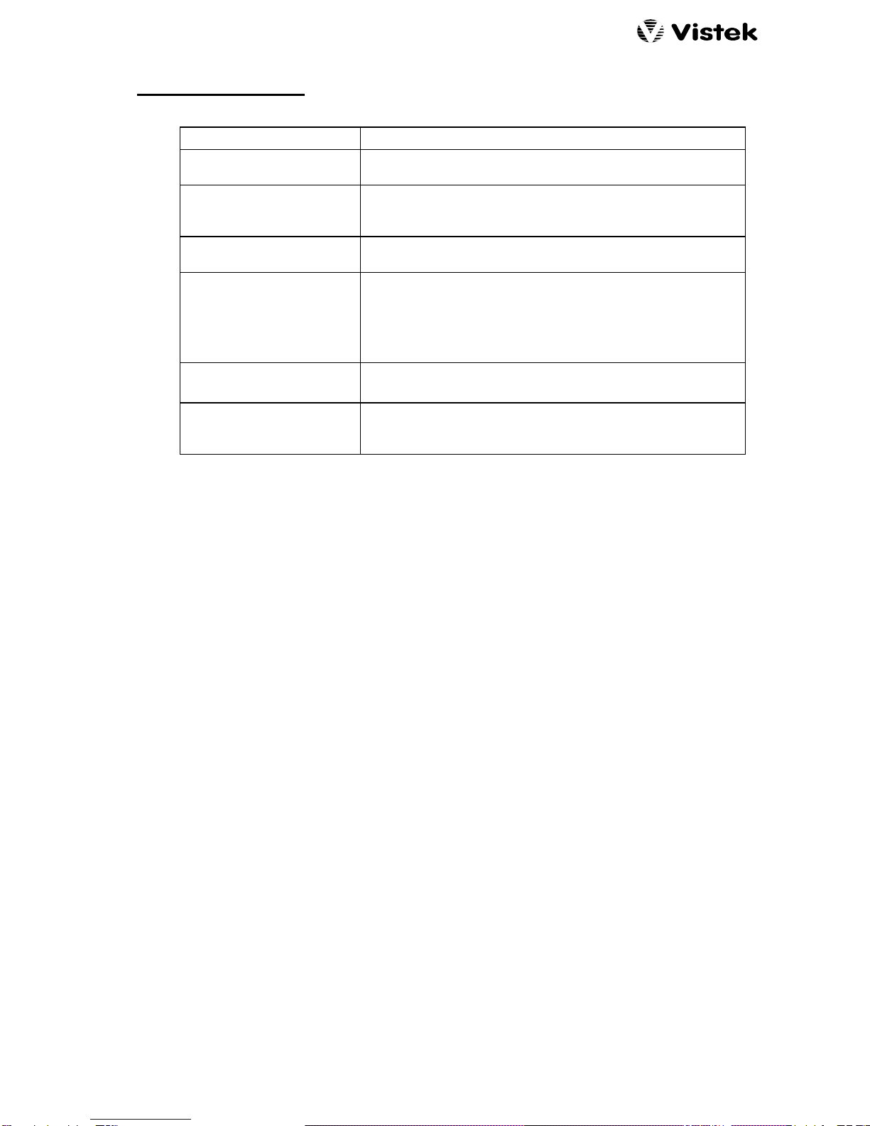
4. TROUBLE SHOOTING
SYMPTOM POSSIBLE CAUSE AND CURES
Cannot select any
parameter on Front Panel. Is power applied? Observe the +5V LED.
Cannot select Hadj or Vadj
parameters, but others are
OK.
Min Del parameter is set. Section 3.9.
Lock-Adj is set. Section 3.11.2.
Changing Hadj and Vadj
has no effect. No reference and REF FL MODE is DOWN so setting
minimum delay. Section 3.11.3.
Not Synchronising Check that a reference is applied.
Check that the reference is the same format as the SDI input,
otherwise the unit tracks the SDI input.
Check that the measurement apparatus is connected in a
suitable manner.
O/P Black No I/P, and FL Mode set to Cut to Black. Section 3.7
Input Selection set to Black
Can select a parameter, but
cannot change anything. The unit is probably in REMOTE mode. You can still select a
parameter to see how it has been set over DART, but cannot
change anything unless you are in LOCAL mode.
Table of contents


