VitalBase Vibby Leaf Manual

TD Technical Specification V2.0 July 16 Page 1
Leaf
Multi Interface – IOT Gateway
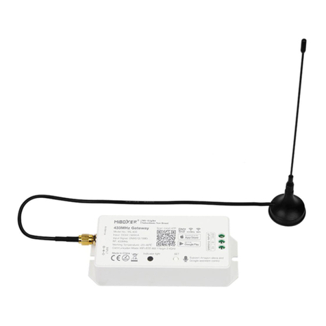
The Vibby Leaf is an ISM 868Mhz Transceiver designed to connect different
peripherals such as Vibby Oak Fall Detector, Smoke sensor or others to a host
terminal using standard simple protocols.
In its standard configuration, the Vibby Leaf is configured to use the proprietary
VitalBase RF Protocol and a simple ASCII host protocol.
Other custom protocols can be implemented on demand.
Due to its small and compact enclosure, the Vibby Leaf can be installed as a desktop
device, wall-mounted device or integrated into walls, ceiling or bedheads.
Thanks to its numerous standard connectors, it is easy to plug and install.

TD Technical Specification V2.0 July 16 Page 2
1VIBBY LEAF DESCRIPTION IN RS485 CONFIGURATION
By default, data is received by RF communication from VitalBase devices, and is converted
into a default host protocol based on ASCII code which is easy to interpret:
-Each event is stored in one and only one frame (constituting one line), and terminated
by a combination of CR+LF.
-Each frame is divided into three different fields, which are separated by a space or
tabulation. Here are these three fields, in order:
oFirst Field: Vibby Leaf PCB’s serial number (which is not automatically the one
printed on the product box label). It is made up of 12 ASCII characters, in which
the last three ASCII characters are « x » (They are in fact not transmitted by RF. As
they are thus unknown, an « x » is printed instead.)
oSecond Field: It provides the event type in ASCII. The possible events are:
« Button »: signals a manual push on the alarm button.
« Fall »: alarm event corresponding to a confirmed fall detection (sent after
pre-alarm vibrations, if those ones are not cancelled by an activity
recovery).
« UnconfirmedFall »: alarm event that appears after an unconfirmed fall
detection (sent before the pre-alarm phase): this event is optional.
« Periodic » : Technical and automatic event (silent) sent every 23 hours
(depending on RF protocol), in order to verify if the device is functioning
properly or not.
« Bind »: Special event (optional) that happens during a Fall Detector
pairing. This event can also be transmitted when a long push on the alarm
button happens. It may be used for different purposes, such as a nurse
taking care acknowledgement (optional).
oThird Field: Battery state in ASCII characters:
« LowBat »: Battery is low on energy and needs to be replaced.
« OkBat » : Battery is Ok.

TD Technical Specification V2.0 July 16 Page 3
2DESCRIPTION OF THE TD CSV HOST PROTOCOL
As an alternative, a second host protocol named TD CSV is available. The structure of the
outputted frame is almost the same as the previously presented protocol, but the type and
the number of fields actually present in the frame are configurable, thanks to an AT
command (see below).
-Like the previously presented host protocol, each frame is terminated by CR+LF ASCII
characters, and organized into fields, each one separated from the others by a special
ASCII character. In this protocol, the special character is a colon character “:”.
The available fields are:
oVibby Leaf PCB’s serial number (which is not automatically the one printed on the
product box label). It is made up of 12 ASCII characters, in which the last three
ASCII characters are « x » (They are in fact not transmitted by RF. As they are thus
unknown, an « x » is printed instead.)
oThe Receive Signal Strength Indicator (RSSI) that gives a measure of the power
level of the received signal. The result is a negative number in dBm unit that could
range down to -127 dBm and up to 14 dBm.
oThe event type in ASCII characters. The possible events are:
« help » : signals a manual push on the alarm button.
« fall »: alarm event corresponding to a confirmed fall detection (sent after
pre-alarm vibrations, if those ones are not cancelled by an activity
recovery).
« unconfirmedfall » : alarm event, that appears after an unconfirmed fall
detection (sent before the pre-alarm phase): this event is optional.
« info » : Technical and automatic event (silent) sent every 23 hours
(depending on RF protocol), in order to verify if the device is functioning
properly or not.
« bind »: Special event (optional) that happens during a Fall Detector
pairing. This event can also be transmitted when a long push on the alarm
button happens. It may be used for different purposes, such as a nurse
taking care acknowledgement (optional).
oBattery state in ASCII characters:
« batlow » : Battery is low on energy and needs to be replaced
« batok » : Battery is Ok

TD Technical Specification V2.0 July 16 Page 4
As mentioned before, the TD CSV host protocol is reconfigurable, thanks to AT command
“AT$HC=<value>” (see 4- Command List). The number and the nature of fields can be
changed.

TD Technical Specification V2.0 July 16 Page 5
3FOREWORD / INTRODUCTION
Whatever the interface adapter used, the default settings for the UART are:
•9600 bauds
•8 bits
•1 start bit
•1 stop bit
•No parity
•No flow control
The Vibby Leaf UART interface has two modes of operation:
•A “connected” mode, where the received RF frames are sent to the host using a given
host communication protocol (the green LED signals when a frame is received)
•A “command” mode, where the VIBBY LEAF interacts with the host using a set of AT
(Hayes compatible) commands: this enables the setting of various VIBBY LEAF
parameters
The available communication modes are the following: USB, RS485, RS232, TTL and WIFI.
The user is able to choose it thanks to an AT command (see 4- Command List below).
HOWEVER, regardless of the current mode, an USB connection prevails over the other
communication modes. For instance, if the Vibby Leaf is connected by USB and by RJ45 for
RS485 protocol, even though the communication mode is set to RS485 mode, information
can only be sent to the device by USB.
At the Vibby Leaf initialization, if the USER button is press for 10 seconds, both LEDs will
toggle during 3 seconds, and all parameters are reset to their default factory value (same as
the AT command in 4- Command List below), and the UART is configured to its default
settings above.
After the Vibby Leaf initialization, during 30 seconds, the user is able to bind a single Fall
Detector device to the relay, by pressing the USER Button. User has 60 seconds to send a
binding frame using the TD RF Protocol. According to the options set in AT$RLCONF (see 4-
Command List below), if the bind device sends a “fall” or “help” event instead, the relay
reacts by switching.
The toggling of the yellow LED will warn that the relay bound at the initialization is
confirmed.

TD Technical Specification V2.0 July 16 Page 6
4COMMAND LIST
This section describes the different AT commands available in the Vibby Leaf.
Command Purpose
AT? Display the available AT commands
AT/ Repeat the last AT command
ATD Enter connected mode:
-Start the RF receiver
-Wait for incoming RF frames from VitalBase devices
ATE<value> Enable command echo (0= disable, 1= enable, default = 1)
ATF<value> Enable full-duplex operation (0= half-duplex = ignore remote echo –
485 mode, 1= full-duplex, default = 0)
ATH Hangup connection (no effect on VIBBY LEAF, only present for
compatibility)
ATI[<value>] Get device information, based on <value>:
-No value: returns “Telecom Design VBR2”
-5: returns firmware release date “M<mm>+<yyyy>”, where
<mm> is the month number and <yyyy> is the year number
-7: returns the serial number (12 digits)
-13: returns the firmware release: “SOFT<xxxx>”, where <xxxx>
is the firmware release number
ATO See
ATD
command

TD Technical Specification V2.0 July 16 Page 7
ATQ<value> Set result code format mode (0= verbose, 1= abbreviated, default =
0)
ATT See
ATD
command
ATV<value> Set result code presentation mode (0= numeric, 1= ASCII, default =
1)
ATX<value> Set CONNECT result code format (0= no connect speed, 1= with
connect speed, default = 1)
ATZ Set all current parameters to user defined profile
AT$HC=<value
> Configure the information when using CSV host protocol (ID,
BATTSTATE, EVENTTYPE, RSSI, …)
AT&F Reset all parameters to factory defaults
AT&V Display current configuration
AT&W Store parameters into Flash memory
AT+IPR=<valu
e>
AT$IPR=<valu
e>
AT+IPR?
AT+IPR=?
Set local baudrate, default is 115200 change immediately the speed
Set local baudrate, default is 115200 change only after the command
AT&W
Get local baudrate. Return value is
“+IPR:0(Auto),300,600,1200,2400,4800,9600,19200,38400,57600,11
5200”
AT$A=<value>
AT$A?
Set autoconnect mode (0= no autoconnect on startup, 1=
autoconnect on startup, default = 1)
Get autoconnect mode
AT$HC? Get the configuration of the CSV Protocol
AT$H=
<value>
Set local junction host protocol (1= TD protocol, 2= Reserved, 3=

TD Technical Specification V2.0 July 16 Page 8
AT$H?
TD CSV protocol, default = 2)
Get host protocol
AT%D<value> Set debug mode (0= disabled, 1, enabled, default = 0)
AT$Z Reset the Vibby Leaf device
AT$R=<value>
AT$R?
Set RF protocol (1= TD protocol, 2= Reserved protocol, default = 1)
Get RF protocol
AT$I=<value>
AT$I?
Reserved
Reserved
AT$MUX=
<value>
AT$MUX?
Set Multiplexer on Value: IDLE, TTL, RS232, RS485, WIFI
Default:RS485
Get Multiplexer setting (if USB communication is used, the
multiplexer setting can be different: further information at 3-
foreword/introduction
AT$RLCONF=
MODE,
POLARITY,
DELAY
AT$RLCONF?
Set the relay configuration: MODE corresponds to the control mode
(0= Manual, 1= Auto, default = 0). Manual means that the relay can
only be controlled by using the AT command to set it on and off:
“AT$RELAY”. If mode is on Auto, the relay is also controlled by the
bound
devices: each fall or help event causes a relay commutation
during DELAY MS. POLARITY sets the polarity of the relay (if it is
initialized at 0, RJ45 2&3 are by default shorted by relay and if set to
1, RJ45 3&4 are by default shorted by relay).
Get the configuration.
AT$RLBIND=
<value>
AT$RLBIND?
This command erases all the device serial numbers bo
und to the
relay, and allows the user to register <value> devices and binds
them to the relay. <value> cannot exceed 4.
Get the serial number of each device bound to the relay
AT$RELAY=
<value> Set the relay state: • At 0, RJ45 2&3 are shorted by relay
• At 1, RJ45 3&4 are shorted by relay

TD Technical Specification V2.0 July 16 Page 9
5VERBOSE AND NUMERIC RESULT CODES
All AT commands will terminate its response with a result code from the following table:
Verbose Format Numeric
Format
Meaning
OK 0 Command executed, no errors
CONNECT[
<speed>] 1 Connection established
NO CARRIER 3 Link not established or disconnected
ERROR 4 Invalid command or command line too long
BUSY 7 Remote station busy (not used by Vibby Leaf)

TD Technical Specification V2.0 July 16 Page 10
6RJ45 INTERFACE
Table of contents

