VITECTOR FRABA RAY-LG 35 Series User manual
MANUAL (TRANSLATION)
RAY-LG 35XX
Page 1 RAY-LG 35XX Version: 1.0
Features
▪Type E Safety Device acc. EN 12453:2017
▪Safety Cat. 2, PL D according to EN ISO
13849-1:2008
▪Certified According to EN 12978: 2009
▪SIL 2 certified
▪Fulfils SIL 2 Without Testing (OSE Output)
▪TÜV –EC Type Examination Certified
▪Direct Mounting in Door Tracks with Blanking
▪Partial Opening Function
▪High Detection Capability Due to Cross Beams
▪Designed for Door Speeds up to 1.6 m/s
▪Selectable Transistor PNP/NPN or OSE Output
▪Cross Section of Only 12 mm × 14,5 mm
▪Easy Alignment
▪Ideal for Retrofit with OSE-C Control Unit
▪IP68 Waterproof Housing (Cable: IP67)
MANUAL (TRANSLATION)
RAY-LG 35XX
Page 2 RAY-LG 35XX Version: 1.0
Safety Information
The RAY-LG was developed and manufactured
using state-of-the-art systems and technologies.
However, injury and damage to the sensor can still
occur.
To ensure safe conditions:
▪Read all enclosed instructions and information.
▪Follow the instructions given in this manual
carefully.
▪Observe all warnings included in the
documentation and attached to the sensor.
▪Do not use the sensor if it is damaged in any
way.
▪Keep the instruction manual on site.
The RAY-LG should only be installed by authorized
and fully trained personnel! The installer or system
integrator is fully responsible for the safe integration
of the sensor. It is the sole responsibility of the
planner and/or installer and/or buyer to ensure that
this product is used according to all applicable
standards, laws and regulations in order to ensure
safe operation of the whole application.
Any alterations to the device by the buyer,
installer or user may result in unsafe operating
conditions. FRABA B.V. is not responsible for any
liability or warranty claim that results from such
manipulation.
Failure to follow instructions given in this manual
and/or other documents related to the RAY-LG may
cause customer complaints, product recalls,
damage, injury or death.
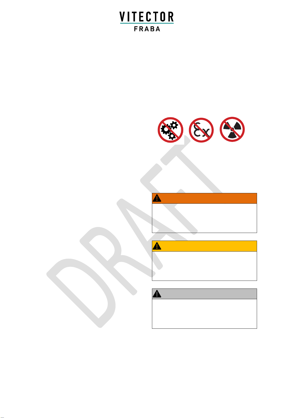
Non-intended Use
The RAY-LG must not be used for:
▪Equipment in explosive atmospheres
▪Equipment in radioactive environments
▪Protection of dangerous machine
Use only specific and approved safety devices for
such applications, otherwise serious injury or death
or damage to property may occur!
Safety Message Categories
WARNING:
Serious Health Risks
Highlights critical information for the safe use of
the sensor. Disregarding these warnings can
result in serious injury or death
CAUTION:
Possible Health Risks
Highlights critical information for the safe use of
the sensor. Disregarding these warnings can
result in serious injury or death
NOTICE:
Risk of Damage
Disregarding these notices can lead to damage to
the sensor, the door controller and/or other
devices
MANUAL (TRANSLATION)
RAY-LG 35XX
Page 3 RAY-LG 35XX Version: 1.0
Product Description
The RAY-LG is a very reliable SIL 2 certified safety
light curtain. It was developed and designed to
safeguard all types of vertically opening industrial
doors such as sectional or highspeed doors. The
system is ideal for door openings up to 10 m width
and can handle door closure speed of 1.6 m/s. The
opening speed is up to 3 m/s. The emitter and
receiver are preferably installed directly inside the
guide rail. The RAY-LG has a selectable transistor
(NPN/PNP) or OSE output, so one system can
handle all relevant outputs. Selecting the OSE
output allows operation according to EN ISO
13849-1:2015 Cat. 2 without periodic testing of the
light curtain. This output is included in the TÜV
certification of the RAY-LG.
Functionality
The emitter and receiver edges create a grid of
infrared beams offering up to 2.5 m (8.2 ft) in
protection height.
When the infrared beams are interrupted, the
output sends a signal to the connected door
control unit. As soon as the detection area is clear
again, the output switches to indicate that the area
is "clear". The blanking system is designed to
mount directly into the guide rails. As the door
closes, the RAY-LG recognizes the door as such
and does not switch the output.
Once the door has arrived at the fully closed
position, the output signal will be switched off.
Intended use
RAY-LG is certified according to
EN ISO 13849-1:2015 and EN 12978:2009 if the
door is monitored over its full height up to 2.5 m
(8.2ft). It is designed and approved for mounting
and use in- and outside the side guides of
industrial doors and serves as E-device presence
detection according to EN 12978:2009 and
EN 12453:2017.
The RAY-LG 35XX fulfills the safety level up to
SIL 2 according to EN 61508:2010 and the
category 2 (cat. 2) / performance level d (PL d)
according to EN ISO 13849-1:2015.
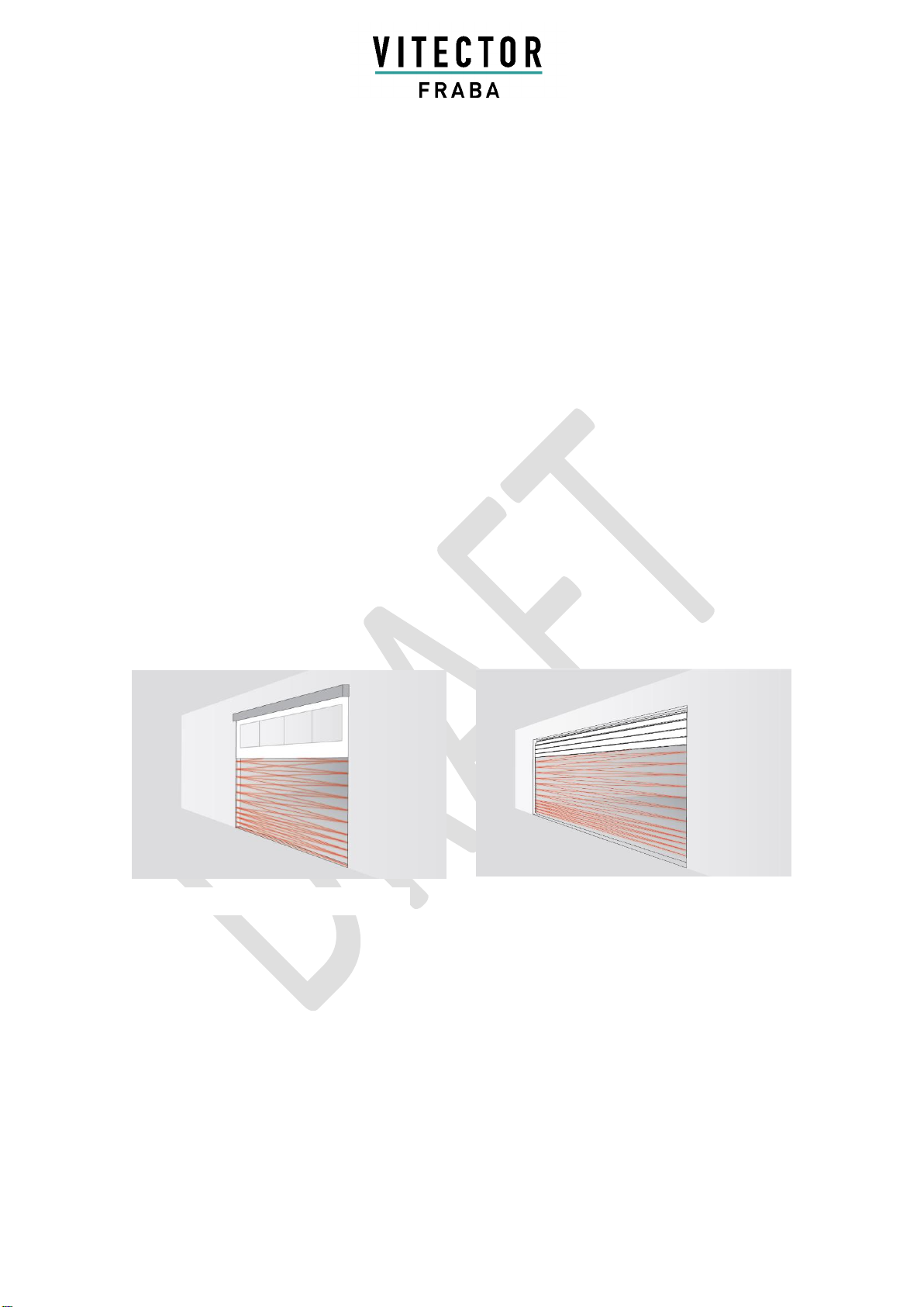
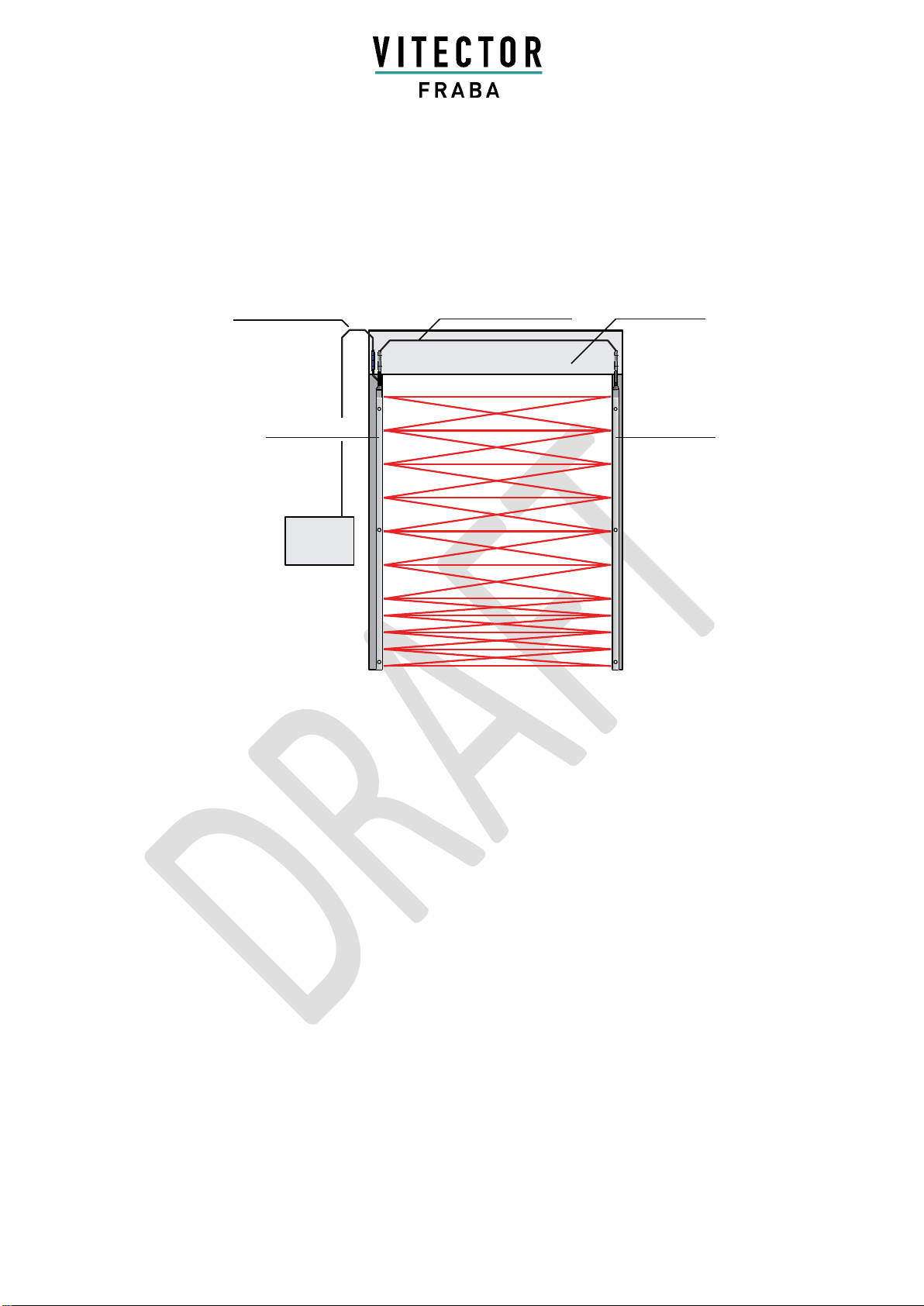
Figure 1: Rolling door with door blanking
Figure 2: Sectional door with door blanking
MANUAL (TRANSLATION)
RAY-LG 35XX
Page 4 RAY-LG 35XX Version: 1.0
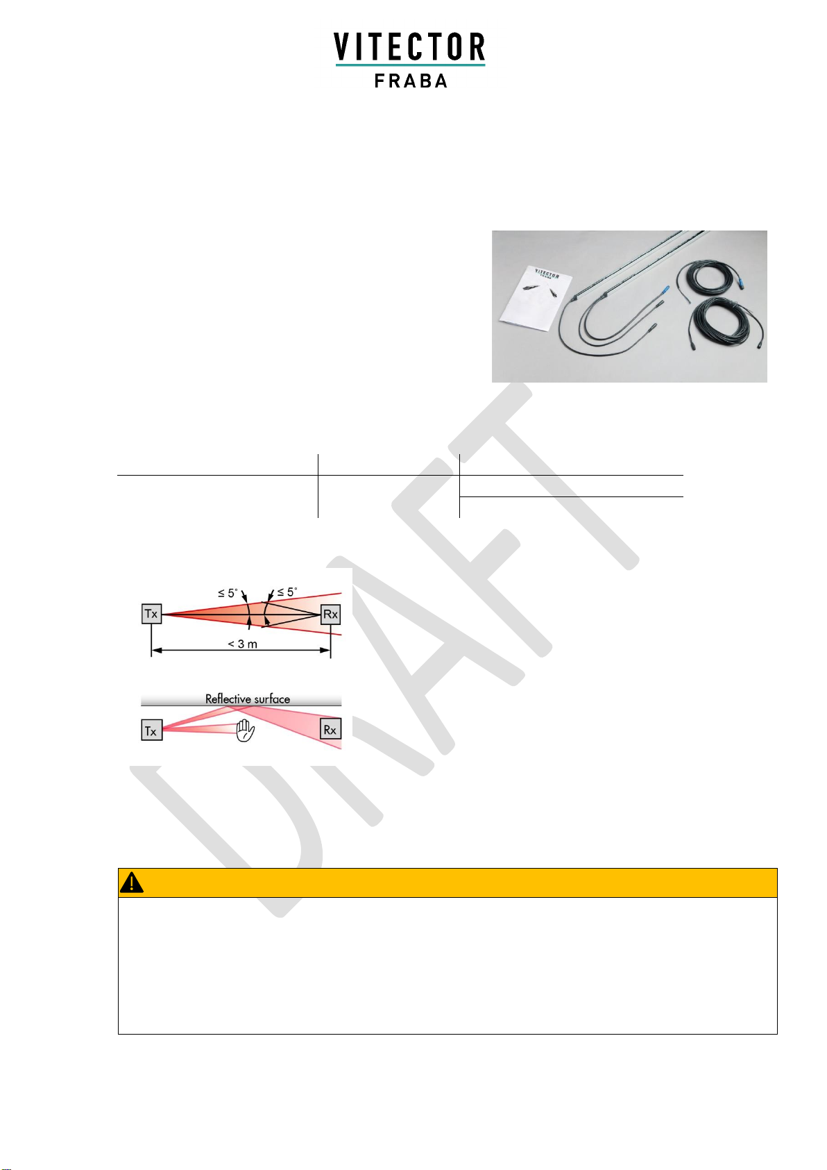
Delivery Set
RAY-LG comes with a customer-specific delivery package.
A typical delivery package contains:
▪1 x RAY-LG transmitter bar (Tx)
▪1 x RAY-LG receiver bar (Rx)
▪1 x Synchronization cable 10 m (33 ft)
▪1 x Connection cable 5 m (16.5 ft)
▪1 x Installation and Operation Manual
Type Key
RAY-LG A B CD
A: Output
B: Aperture Angle
CD: Number of Optical Elements
A= 3: Semiconductor/OSE
B= 5: ±5°
CD = 20: 20 Elements (2060 mm)
CD = 22: 22 Elements (2420 mm)
Alignment and Calibration
The optical axis of the emitter (Tx) and the receiver edge (Rx) need to
be aligned towards each other to ensure the light curtain functions
reliably.
Reflective surfaces near to or parallel to the detection area can cause
reflections and interfere with the RAY-LG's functions. Keep a reasonable
distance between the sensor edges and any reflective surface.
A self-calibration on each optical beam is implemented. At the power- up
the ideal emitting strength will be detected and used. To reduce
interruption caused of dust the system checks the emitting power and
adapt a new higher or lower strength if necessary. After 45 s interruption
a self-reset of the system will be made.
CAUTION:
Damage to the Eye
Although the RAY-LG does not emit dangerous amounts of infrared light, long exposure to intense infrared light
sources can result in damage to the eyes.
- Never look directly into the active infrared emitter from a close distance
Possible health risks - Disregarding these warnings can result in injury
Figure 3: Typical RAY-LG delivery set
MANUAL (TRANSLATION)
RAY-LG 35XX
Page 5 RAY-LG 35XX Version: 1.0
Application Overview
Door Blanking
The RAY-LG can differentiate between a light beam interruption caused by an object and a light beam
interruption caused by the closing door. The RAY-LG does this by analyzing the different interruption
patterns.
Blanking Routine during Door Closure:
The light beam interruption of a closing door starts at the topmost beam going downwards. There are two
ways to achieve blanking:
When the RAY-LG is integrated inside or, in this case matching holes need to be drilled, behind the side
guide, the door moves directly in front of the light curtain. The bottom section of the door needs to be solid
for at least 30 mm over the entire door width to ensure that at least one light element is completely
covered. Hollow extrusion profile may need to get clogged.
Door
Controller
Connection Cable
Synchronization Cable
Door Operator
Receiver
Emitter
Figure 4: RAY-LG application overview
MANUAL (TRANSLATION)
RAY-LG 35XX
Page 6 RAY-LG 35XX Version: 1.0
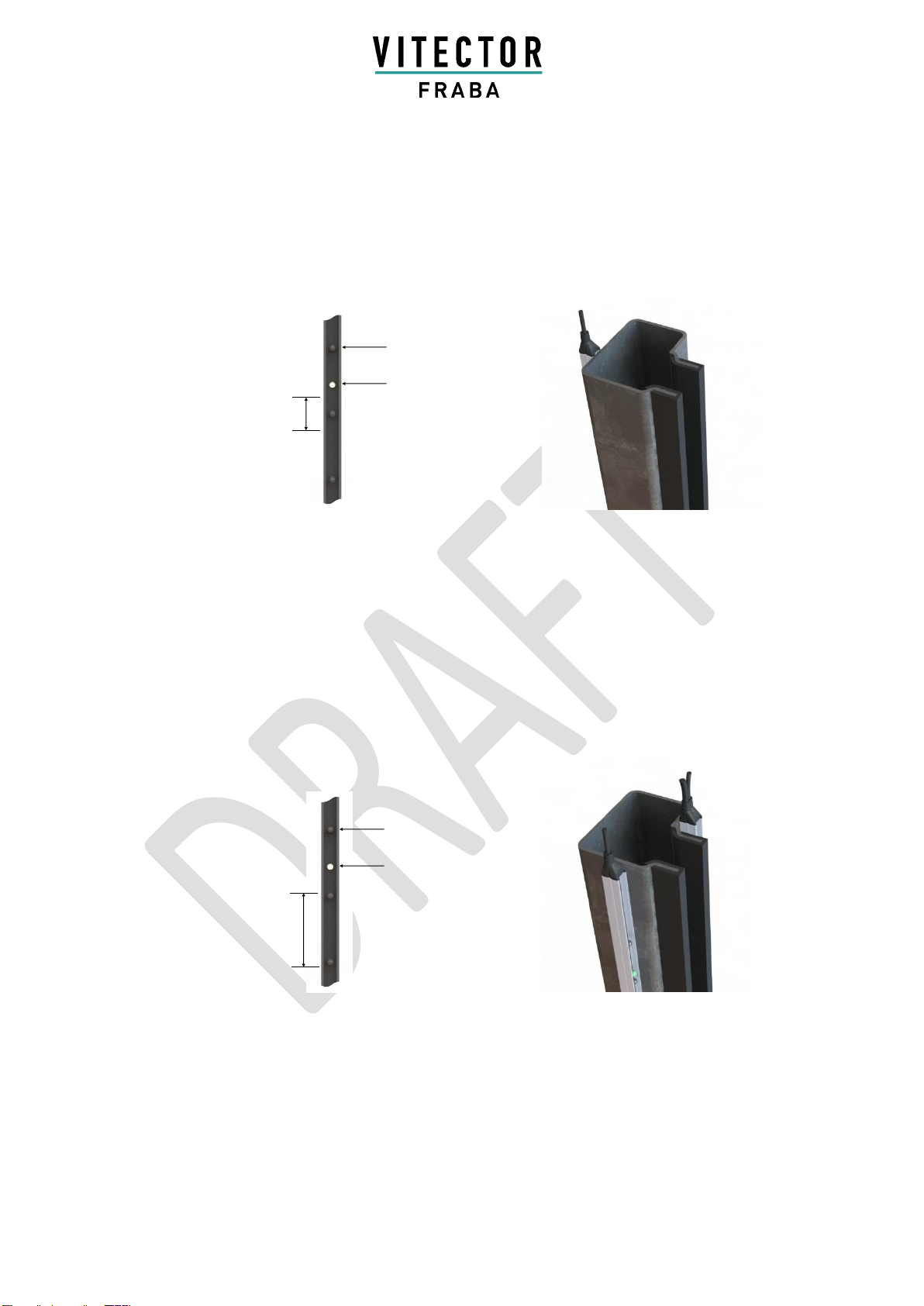
Optical element
Mounting hole
Min. height of the lower
end of the door
Optical element
Mounting hole
Min. distance
always covered
by the beam
blocker
When the installation of RAY-LG is not possible inside the side guide, it may also be mounted from the
back side (Figure 5.1). Holes of min Ø 10 mm must be drilled into the profile to allow the light to pass
through.
If two light curtains are installed parallel to, but not in line with the door panel in front of and behind the
guide rail, the descending door will not interrupt the active beams. (Figure 5.2) However, blanking may still
be required if any obstructing part of the door (e.g. strengthening bars, hinges, junction boxes) interrupt the
light curtain. A beam blocker can be employed to shade the diodes on one side, but it must be mounted so
that at least one element is continuously covered during door closure (Figure 5.2).
3 seconds after the last beam was interrupted by the now closed door, the output signal is interrupted.
Figure 5.1:Door blanking through door edge
Figure 5.2:Door blanking with two RAY-LG sets
MANUAL (TRANSLATION)
RAY-LG 35XX
Page 7 RAY-LG 35XX Version: 1.0
Blanking Routine during Door Opening / Partial Opening Function
The output signal will remain off during the opening of the door until the 11th beam is unobstructed (approx.
500 mm opening height). From this position onwards it will be possible to reverse and close the door in
automatic mode. Successively releasing additional light beams will increase this partial opening position
accordingly. During a later closing cycle, the monitored area and the smart blanking function will be limited
to the previously saved partial opening height, higher positioned light beams will remain blanked.
When the power supply of the RAY-LG is interrupted in a partial opening position, it is necessary to open
the door higher than the safeguarded area to allow the system to undergo an automatic initialization
routine.
Installation
WARNING:
Electrical and Mechanical Hazards
Electrical shock and unexpected door movement can cause serious injury or death.
▪Follow all applicable safety measures
▪Use only specific and approved tools
▪If the RAY-LG must be adjusted, the main power supply must be switched off and marked as “out
of service”.
Serious Health Risks - Disregarding these warnings can result in serious injury or death
▪Never scratch or paint the optical lenses because it
may obstruct the light path! Do not drill additional
holes into the profile. Unpack the profiles just before
installation in order to avoid damage.
▪Do not bend or twist the edges!
▪Oil can damage the cables. Contamination must
always be avoided!
▪Chemical can damage the profile and optical
characteristics. Contact must always be avoided!
NOTICE:
Mechanical Damage to the RAY-LG
▪Do not drill additional holes into the light curtain
▪Do not drill through mounting holes
▪Do not over-tighten the mounting screws
▪Mount the edges on a flat surface
Risk of damage - Disregarding this notice can lead to damage to the sensor, the door controller and / or
other devices

MANUAL (TRANSLATION)
RAY-LG 35XX
Page 8 RAY-LG 35XX Version: 1.0
▪Although the RAY-LG is not sensitive to direct sunlight,
avoid all unnecessary exposure if possible, especially
to the receiver.
▪Avoid interference from blinking lights or infrared light
sources such as photocells or other light curtains.
▪Do not install the RAY-LG in places where the emitter
and receiver edges are directly exposed to light
sources such as FL tubes or energy saving lamps.
▪Make sure to place the connection plugs for both the
emitter and receiver at the same end.
1. Switch off main power to the door control unit
and clearly mark that this system is out of
service before performing any work on the
system.
2. Mount the receiver on one side of the door
with better access to Door control unit for
easier cabling and only use the mounting
holes provided on the sensor bars (See
Figure 6.2).
3. In case of severe disturbances or direct
sunlight mount the receiver on the opposite
side
4. Mount the receiver bar into the guiding track
next to the door control unit (See Figure 5.1).
In order to fulfill EN 12978:2009 the lower end
of the edges must be at the level of the door
closed position (See Figure 6.1).
5. Mount the emitter across from the receiver. If
the receiver is mounted in the guiding track,
the emitter should be mounted in the guiding
track opposite the receiver. Make sure the
optical elements are facing each other (See
Figure 6.1).
6. Connect the emitter with the receiver using
the synchronization cable.
7. Plug the connection cable into the blue plug
on the receiver bar and connect it to the door
controller (See Electrical Connection, p. 9).
8. If using two RAY-LG on sides of the slide
guide rail (See figure 5.2) make sure that
both receiver bars are not mounted on the
same side of the door to avoid interference
between two sets.
Figure 6.1:Proper Mounting
Figure 6.2:Mounting Holes
MANUAL (TRANSLATION)
RAY-LG 35XX
Page 9 RAY-LG 35XX Version: 1.0
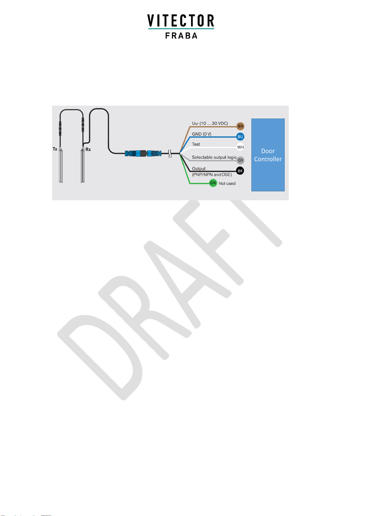
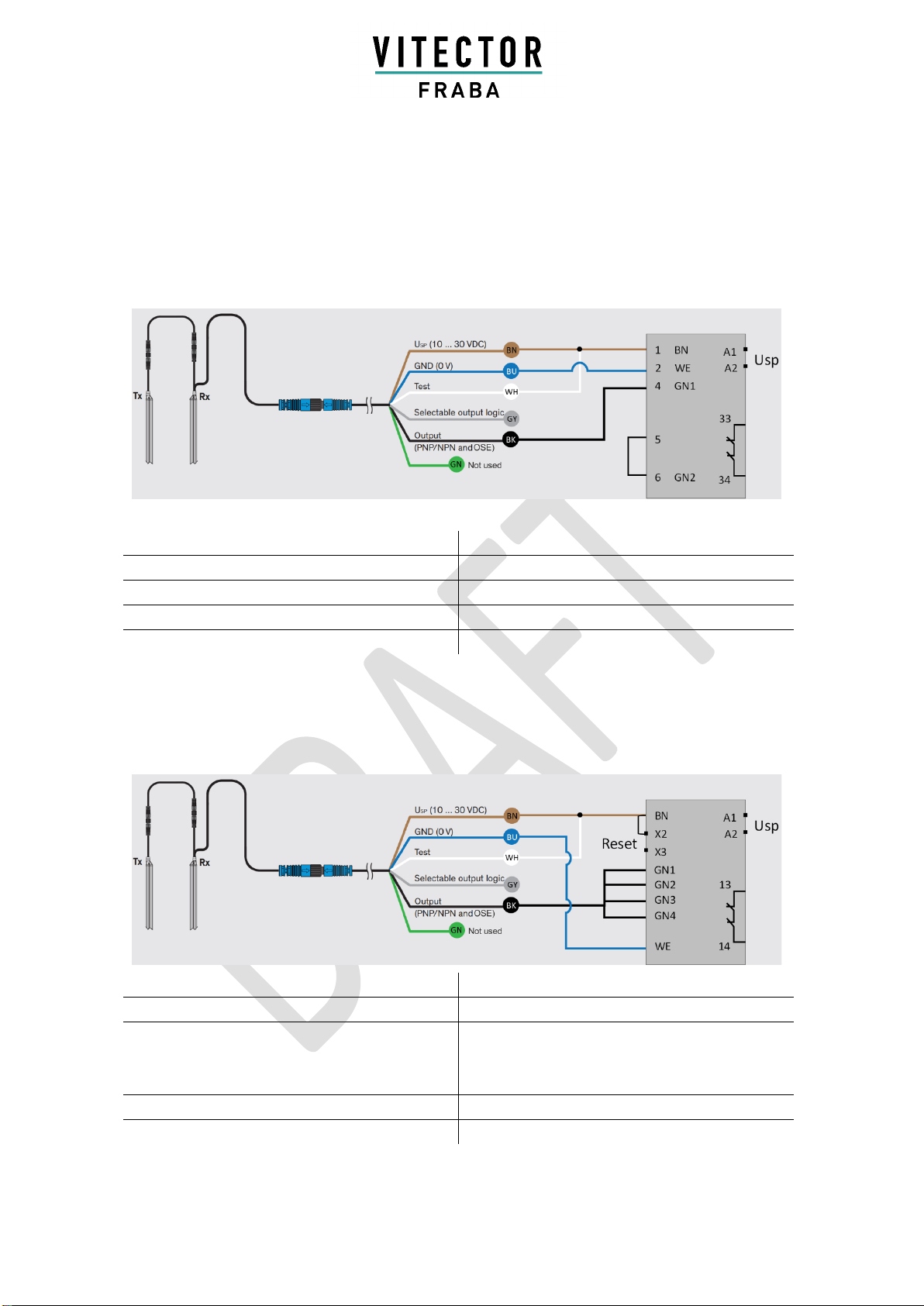
Electrical Connection
Figure 7: Connection diagram
Important: Any unconnected (not used) wire must be separated and isolated.
Output
When an obstruction is detected, (OBJECT
DETECTED) the RAY-LG output changes after
response time t2. When the object leaves the
surveillance area (NO OBJECT) the RAY-LG
output switches back after release time t3 (See
Timing Diagram, p. 11)

MANUAL (TRANSLATION)
RAY-LG 35XX
Page 10 RAY-LG 35XX Version: 1.0
Changing the output logic
Output (PNP/NPN) logic is set using the gray wire.
The default logic is LO (light-on) (See Timing
Diagram, p. 11).
The output logic is LO if the gray wire is connected
to GND (0 V). Connecting the gray wire to USP (10
to 30 VDC) changes the output logic to DO (dark-
on) (See Figure 9). If the gray wire is not
connected (floated), the output logic changes to
the OSE signal.
Gray wire Output logic
Not connected (floated) OSE
Connected to GND (0 V) LO
Connected to USP (10 to 30 VDC) DO
Table 1: Output (PNP/NPN) logic selection table
LO/DO selector not connected (floated)
LO/DO selector connected to USP
LO/DO selector connected to GND (0 V)
Figure 8: Output logic
MANUAL (TRANSLATION)
RAY-LG 35XX
Page 11 RAY-LG 35XX Version: 1.0
OSE Output
The OSE is a 1 kHz safety output allowing for
monitoring according to EN ISO 13849-1:2015,
without using a test signal. For the OSE version
the test input (white cable) of the light curtain has
to be connected to supply voltage (brown cable).
As long as the monitored area is free, the OSE
output sends a 1 kHz signal. When an object
enters the monitored area (OBJECT DETECTED)
the OSE output switches to LOW/GND (0V). When
the object leaves the monitored area (NO
OBJECT) the frequency starts again (See Timing
Diagram, p. 11).
Test Input
To fulfill EN ISO 13849-1:2015, the RAY-LG with
PNP/NPN output must be tested by the door
controller before each door closing cycle. The
RAY-LG is available with test active LOW.
Important: When the OSE output is used, using
the test input is not necessary to achieve
monitoring according to EN ISO 13849-1:2015. In
this case, the white wire must be connected to the
USP.
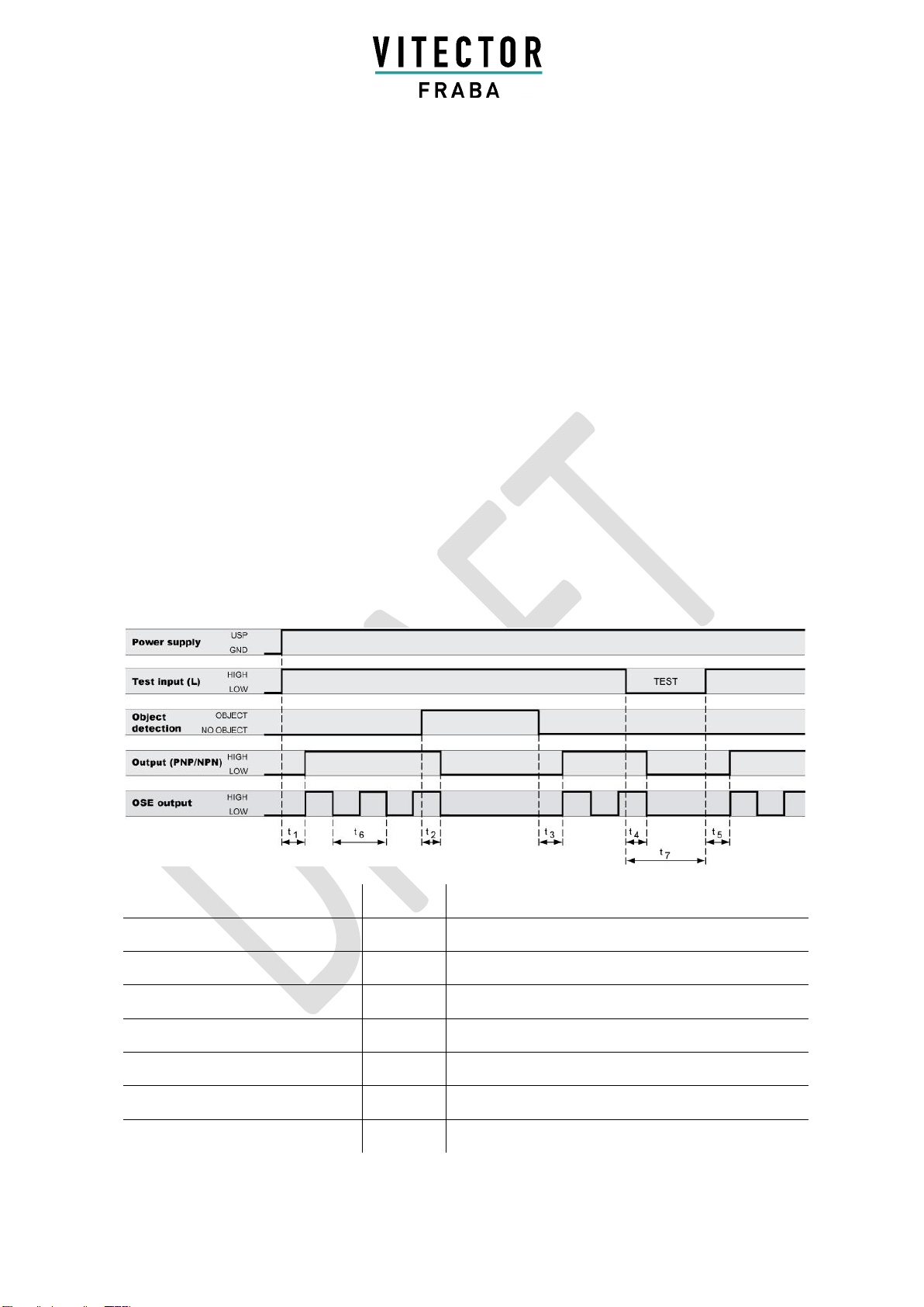
Timing Diagram
Figure 9: General timing diagram
Time
Value
Power up time
t1
max. 1,700 ms
Response time with 22 elements
t2
typ. 40 ms / max. 80 ms
Release time
t3
max. 50 ms
Test response time
t4
max. 80 ms
Restart time
t5
max. 200 ms
OSE sequence time
t6
1 ms
Test time
t7
>100 ms
Table 2: General timing table

MANUAL (TRANSLATION)
RAY-LG 35XX
Page 12 RAY-LG 35XX Version: 1.0
PNP / NPN
Power supply USP
10…30 VDC
Power supply GND
0 V
Test input HIGH
> 10 VDC
Test input LOW
< 2 VDC
Output HIGH
> USP - 2 VDC
Output LOW
< 2 VDC
OSE output HIGH
3.4…4.2 VDC
OSE Output LOW
< 1 VDC
Table 3: General value table
Start-up
1. The door must be opened completely, and
the monitored area must be unobstructed.
2. Switch on main power supply and power up
the door control unit. The LEDs blink during
power up.
3. Check the LED on both sensor bars (power,
status).
4. Test if the system is working correctly by
letting the door open and close, interrupting
the light during the opening and closing
process.
LED Status Description Receiver Edge
green LED
red LED
Sensor status
Light curtain free
Light curtain interrupted
Start-Up (slow blinking)
Internal Malfunction (fast
blinking)
No Power or light curtain
defective
LED on LED off LED blinking
Table 4: LED status description receiver edge
LED Status Description Emitter Edge
green LED
Sensor status
Power ok
No Power or not within the limits or
edge is defective
LED on LED off
Table 5: LED status description emitter edge

MANUAL (TRANSLATION)
RAY-LG 35XX
Page 13 RAY-LG 35XX Version: 1.0
Troubleshooting
Emitter (Tx)
Receiver (Rx)
Action
LED off
LED off
▪Check electrical connections.
▪Check supply voltage of the door controller.
LED off
LED red
▪Check the connection of the synchronization cable.
LED green
LED always green
(also, when
interrupted)
▪Make sure the sensor edges are not mounted
close to any shiny or reflective surface.
▪Restart the system.
LED on/off
LED on/off
(flickering red)
▪Check power supply.
▪Check connections.
LED green
LED on/off, min. 100ms
off (red, slow blinking)
▪Make sure the protective field is clear of interruption
▪Check the alignment of the light curtain
▪Clean elements.
LED on
LED switching
between red
(interrupted) and
green (free), sporadically
flickering
▪Make sure the protective field is clear of interruption
▪Clean the elements
▪Make sure that the cables and sensor bars are located
away from sources of electromagnetic interference.
▪Ensure that the emitter and receiver are correctly
aligned and remain so during door closure (e.g. that
vibrations do not cause edges to become misaligned).
▪Restart the system.
LED green
LED always red
▪Make sure the protective field is clear of interruption.
▪Reopen the door completely.
▪Clean the elements.
▪Check the alignment of the light curtain.
▪Check that the test input is connected to the test output
signal of the door control unit and that the signal level
and logic (HIGH/LOW) are correct. If the test input is not
used, connect it permanently to USP.
▪Measure the USP voltage.
▪Restart the system.
LED off
LED on/off, min. 100ms
off (red, slow blinking)
▪Check the connection of the synchronization cable.
LED green
LED on/off (red, fast
blinking, 5 Hz)
▪Internal error occurred
▪Restart the system.
▪Replace Rx edge.

MANUAL (TRANSLATION)
RAY-LG 35XX
Page 14 RAY-LG 35XX Version: 1.0
Important: Whenever a parameter is changed, the system must be restarted. If a problem persists, please
contact your local FRABA VITECTOR representative. Visit www.vitector.eu for contact data.
Maintenance
Although the RAY-LG does not need regular maintenance, a periodic functional check is strongly
recommended:
▪Make sure the optical elements are clear of dirt and dust. If necessary, clean the front surface with a
soft towel.
▪Make sure the profiles are securely fastened.
▪Check the mounting position, cable routing, and connection of the sensor.
Disposal
Disposal should be done using the most up-to-date recycling technology according to local regulations and
laws. There are no harmful materials used in the design and manufacture of the sensor. Traces of such
dangerous materials may be found in the electronic components but not in quantities that are harmful.
NOTICE:
Damage to the optical elements
▪Never use any solvents, cleaners or mechanically abrasive towels or high-pressure water to clean
the sensor
▪Avoid scratching the optical elements while cleaning

MANUAL (TRANSLATION)
RAY-LG 35XX
Page 15 RAY-LG 35XX Version: 1.0
Technical Data of RAY-LG 35xx
Optical
Operating range
1…10 m (3ft…33 ft)
Number of
elements
20, 22
Max. ambient
light
100,000 Lux
Max. protection
height
2,500 mm (98.5 in)
Mechanical
Cross section
12 mm × 14.5 mm (0.47 in ×
0.57 in)
Housing material
Natural anodized aluminum
Enclosure rating
IP68 (Cable: IP67)
Temperature
range
−40 °C…+60 °C (−40
°F…+140 °F)
Electrical
Supply voltage
USP
10…30 VDC
Current
Consumption with
22 elements at 24
VDC
50 mA
Output
PNP/NPN (push-pull) and
OSE
Output load
100 mA, 100 nF
Typ. response time
with 22 elements
40 ms
Max. response time
with 22 elements
80 ms
Max. door speed
closing speed
1.6 m/s (5.3 ft/s)
Max. door speed
opening speed
> 3 m/s
Status LED Rx:
Object detected: red
No object detected: green
Power LED Tx:
Power OK: green

MANUAL (TRANSLATION)
RAY-LG 35XX
Page 16 RAY-LG 35XX Version: 1.0
General
EMC emission
EN 61000-6-3:2007
EN 12015:2014
EMC immunity
EN 61000-6-2:2005
EN 12016:2013
Vibration
EN 60068-2-6:2007
Shock
IEC 60068-2-27:2008
RoHS
2011/65/EU
Certificates
CE, TÜV
Safety category
EN 12978:2009
EN 61508:2010, SIL 2
EN ISO 13849-1:2015, Cat.
2, PL D
EN 12453:2017, E Device
Applicable
standards
UL 325:2012
Synchronization and electrical connection
Extention cable
Length
10 m (33 ft)
Connector
M8, 4 pins, A-coded
Diameter
Ø 3.5 mm (Ø 0.14 in)
Material
PVC, black
Plug color
Black
Wires:
brown
blue
black
white
AWG26
USP
GND (0 V)
Communication
Not used
Connection Cable
Length
5 m (16.5 ft)
Connector
M8, 6 pins, A-coded
Diameter
Ø 4.2 mm (Ø 0.14 in)
Material
PVC, black
Plug color
Blue
Wires
brown
blue
black
white
gray
green
AWG26
USP
GND (0 V)
Output (PNP/NPN and OSE)
Test input
LO/DO selector
Not used
MANUAL (TRANSLATION)
RAY-LG 35XX
Page 17 RAY-LG 35XX Version: 1.0
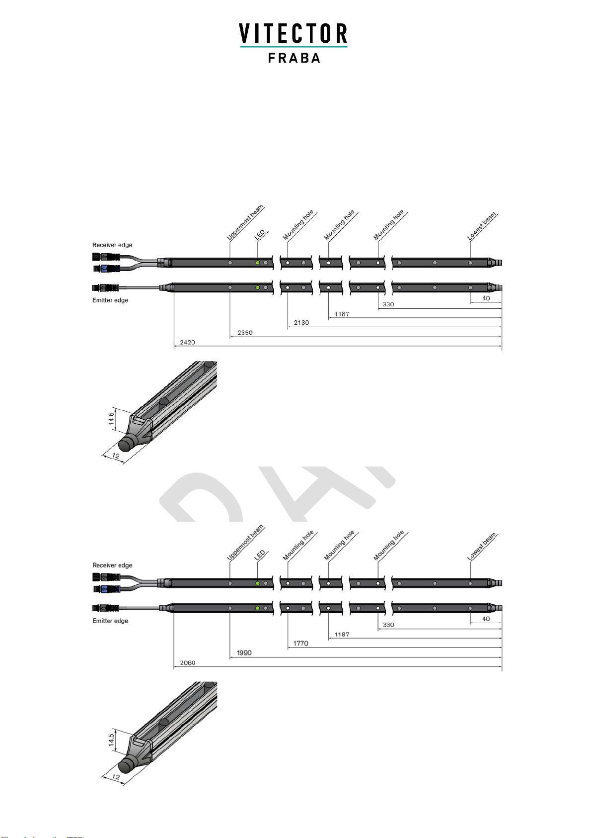
Dimensions
Measurements for 22 elements (all dimensions in mm)
Figure 10: RAY-LG 3522 Dimensions (mm)
Measurements for 20 elements (all dimensions in mm)
Figure 11: RAY-LG 3520 Dimensions (mm)
MANUAL (TRANSLATION)
RAY-LG 35XX
Page 18 RAY-LG 35XX Version: 1.0
Control Unit OSE-C 2300 or OSE-C 2301 / OSE-C 2323 or OSE-C 2324
Supply Voltage USP
24 VDC or 230 VAC
Dimensions
123 x 83 x 61 mm
Enclosure Rating
IP56
Safety Category of the Control Unit
3 acc. EN 13849-1:2008
Performance Level of the Control Unit
c acc. EN 13849-1:2008
Please pay attention to the operating manual of the control unit!
Control Unit OSE-C 5024
Supply Voltage USP
24VAC/DC
Dimensions
22.5 x 100 x 120 mm
Enclosure Rating
- Housing
- Terminal
IP40
IP20
Safety Category of the Control Unit
3 acc. EN 13849-1:2008
Performance Level of the Control Unit
d acc. EN 13849-1:2008
Please pay attention to the operating manual of the control unit!

MANUAL (TRANSLATION)
RAY-LG 35XX
Page 19 RAY-LG 35XX Version: 1.0
Product Label
Lot No.:
yymmdd: year (2 digits), month, day
mmmmmmmm: manufacturing job number
eeeee: employee number responsible for final test
cccccc: incremental number
Technical Instruction valid from year of manufacture 2019
Disclaimer
© FRABA B.V. all rights reserved. We do not assume responsibility for technical inaccuracies or
omissions. Specifications are subject to change without notice.


