Evinrude 25 HP Owner's manual

1976
DtunER·s-OPERRTOR·s
~~~~~~~
mRnURL
25
HP
models
~~
25602
25603
25652
25653

EVInRUDEE
first in
outboards
welcomes
you
aboard . . .
Outboard
boating
is
one
of
Amencan's
most
popular
participa-
tion
!>ports.
When
you
selected Evinrude,
you
selected a
product
that
has
gained a
reputation
a!>
the
qualttV leader stnce 1909
And,
there
ts
no
doubt
that
this year's
outboards
are
the
fmest ever
produ~d.
Your new Evinrude
outboard
has all
the
most
wanted
features
in
outboard motors. Some of these features, such as qualtty of
workmanship, engmeering excellence, whisper
qwet
operatton,
and dependability, have long been standards at Evmrude. Your
new Evinrude boasts
many
new features
wh1le
retaining
the
best
features developed
in
preceding years. These features,
the
old and
the
new, are designed
to
enhance
your
boating pleasure and add
to
your satisfaction in selecting Evinrude.
Your
new
Evinrude Motor
is
designed and
constructed
to give
you
the
maximum in service and performance. Please
study
th1s
manual so
that
you
Will
have a complete understanding
of
1ts
operation and
to
be able
to
take
full advantage
of
its many
built-in features. EVERYONE
WHO
USES THIS EQUIPMENT
SHOULD READ THIS MANUAL AND
BE
FAMILIAR WITH
THE SAFETY WARNINGS MARKED A .
This manual
is
dedicated as a mariner's companion to help more
fully
enjoy
the
sport
in
comfort
and safety.
For
quick reference,
keep
it
handY when operatong
your
outboard.
HAPPY BOATING
EVInRUDE
r=
MoToRs
TABLE OF CONTENTS
PAGE PAGE
ADJUSTMENTS
. . . . . . . . .
23
Propeller and
Dr
ive
Prn
Tilt
Fnct1on
Adjustment
. . . . . . . 23 Replacement . . . . . . . .
.....
.
25
Steering
Fnction
Adjustment
. 23
Lubn
c
at10n
. . . . . . . . . . . . . .
26
-27
Idle Speed
Adjustment
. . . . . .
24
Propell
er
Care . . . . .. . .. . . . 28
Carburetor
Adjustment
. . .
...
24
Cleanmg Fuel Pump Filter . .
28
EVINRUDE DEALER SERVICE . . . 34
Cond
itiOn
of
Boat
Bottom
28
20
Hour
Check
. ... . . . . . . 34 External Ftntsh . . . . .. . .. ..
28
Repair Serv1ce . . . . . . . .. . . . . .
34
Off
Season Storage 29-30
t P t 34 After
Stonng
-Before Usmg . . 30
Replacemen ar s . .
..
..
. . . .
FEATURES
..
.
..
· · · · · · ·
....
· · · · 4 6
Starboard
V1ew
. . .. . . . . . . . . . . . . 4 SAFETY · · · · · · · · ·
..
· · · · · ·
Port View .
..
........
. .
.. ..
· . · 5
SPECIFICATIONS
.
........
-. . - 6
FUEL AND
LUBRICANT
. . . . . . . 12
Model
and Senal
Number
..
.
..
6
Recommended
Lubricant
..
...
12 STARTING
AND
OPERATION . .
14
Recommended Gasoline . . .
...
12 Fuel
Tank
14
Fuel
Mixture
. . . . . . . . . . . .
...
13 Manual Starttng . . . . . . . . . . 14-16
Fuel Mtxing Instructions
......
13
Shifting
. . . . .
....
.
........
17
Break-in Procedure . . .
...
. · · 13 Speed
Control
17
INSTALLATION INSTRUCTIONS
..
8
Stopping
(Manual Start) . 17
Transom
Height
. . . . . . . . . . . . . . 8 Electric Starting wtth OMC
Propeller Selectton . . . . . . . . . . 8
Two
Lever Remote
Control
18
Lifting and
Carrying
Motor
. . . . 8
How
to Shift and Control
Installing
Motor
. . ..
......
. 8-9 Speed
with
OMC
Two
Installation
of
Electncal Lever Remote Control 19
Equipment . . .. . . . . . . . . . . .. 9 Stopping (Electric Start) 19
Battery and Battery
Box
Removmg
Motor
Cover
......
19
(not
supplied
with
motor)
...
9 Emergency Starttng
..
. . .
...
20
Replacement Keys . . . . . . . . . . . 9 Trailenng . . .
21
Remote Controls (Accessory) 9-10 Trouble Check Chart . . . . . . .
21
Remote Steenng (Accessory) . 10 Coolmg System . . . . . . . 22
Remote Control Cables Shallow Water Operation . . . . 22
(not supplied wtth motor)
...
10 Fuel Economy . . . . . . . . . . 22
Removing
Motor
from Boat 10 Operating m Weedy Water . . . 22
Reverse Lock . . . . . . 10 Salt Water OperatiOn . . . .. 22
Tiltmg . . . .. . .. 10 Operattng
tn
Freezing
Motor
Angle Adjustment
11
Weather . . . . .. . 22
Boat Trim
11
Antt-Corrosion Protection .. .. .
22
ITEMS OF SPECIAL SUBMERGED MOTOR
..
..
. 30
IMPORTANCE . . . . 7
Motor
Dropped Overboard
Boatmg Responsibtlittes 7 (not runntng) . 30-31
Owner's Regtstratton Card 7
Motor
Dropped Overboard
Changes in Address
and/or
(runmng) . . . . . .
....
. .
31
Ownership 7
Motor
Dropped Overboard
Insurance . . .
...
. .
...
· · · · · 7
(m
salt water)
.......
31
Stolen Motors
..
....
..
...
.· 7 Prolonged Submerston
MAINTENANCE . . . . . . .
25
(fresh
or
salt water) . . . . . . .
31
Spark Plug Inspection WARRANTY . . . . . . . . . . . . .
..
32
and Replacement . .
......
25
WARRANTY SERVICE . . . 33
OUTBOARD MARINE CORPORATION 1975
ALL
RIGHTS RESERVED
3
FEATURES
3----
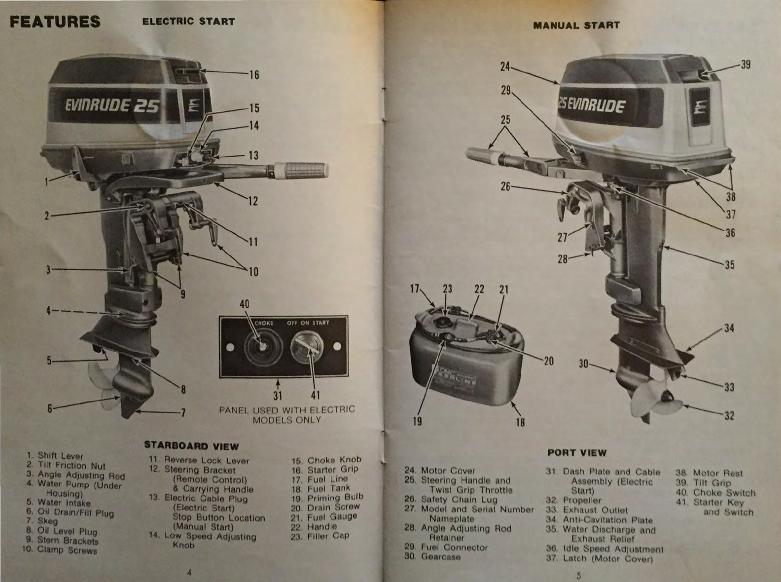
1 Shift Lever
2
Tilt
Fnct1on Nut
3. Angle AdJuattng Rod
4 Water Pump (Under
Houalng)
5. Water Intake
6. Otl Oratn/FIII Plug
7
Sktg
8
011
Level Plug
9 Stern Brackets
10
Clamp Screwa
ELECTRIC
START
40
31
41
PANEl
UStD
Willi
El rCTr
li
C
MODL t S
ONLY
STARBOARD
VlaW
11 Reverse Lock Lever
12
. Steenng Bracket
(Remote Control)
& Carrying Handle
13
. Electric Cable Plug
(Electric Start)
Stop
Button
Locatton
(Manual Start)
14.
Low
Speed
Adjusting
Knob
1b
Ctwk
Knob
16
Stort r Grip
17
Fuol
ltn
o
18 F
ll
I 1 nk
19
PrulllllQ
Outb
20
Ortlln 'crow
21
1-'11
I G
wg
22
H ndl(
23 Ftllt r C P
24
25
28
.
27
28
29
30
MANUAL
START
PORT
VIEW
.32
• l
~4
35
5
SAFETY
·~
~___...,....,..
l'TO·
-.~-~~
~~:
,':';
·_'
-_·
~
:....:.
0
IIOTa:
AdY
ses
you
of
mformatton
or
instructions
vttal ro the operat,on or
~
enance ot your eqwpment.
SPECIFICATIONS
Mooe 25602,
Ma
al
-25652
Electr
c Sta"ldard Leng
th
Odes
25603.
Manua -25653 Electr c
Lorg
S aft
Powernead Two Cyttnder -
Two
Cycle
Alternate F.r ng
Bore
ar'ld
S roke 2
50
x 2.
25
P on 0 sp acement 22 Cub1c Inch
es
Horsepower 25.0 y Certified Brake Horsepower at 5500
RPM
Fu I Speed
Operattng
Range
---------
5000
to
6000
RPM
lg
tJOn
Low
Tensi
on
Aag
neto
Brea er Gap
~
1
~
_ 020
Sperl( Pfug
lU
(
Ll
~~(
1 a
1
~~J..:......~.!.&'-
Champ1on
J4J
Spark P ug Gap 030"
Sper1t
Plug Torque 17-1/2
to
2Q-1
2 ft.-l
bS
Cooftng System Water Pump -
Pos•t111e
and Centnfugal -Thermostat
Carburetor
----
Frlled High Speed, Adjustable
Low
Speed Jet -Choke
Geer
stUft Forward -Neutral -
Re
erse
Gear
RatiO
12
.
21
Gearcase
lubncant
Capacrty 8.3 ozs. (246 cc
.)
Speed Control Twist
Gnp
Throttle
(Remote
Control
OptiOnal)
Propefler 3 Blade.
9"
d1a
x
10
· P1tch
OptiOnal Propellers
-------
3 Blade, Weedless
9"
d1a
x 10''
P1tch
3 Blade, 9
d1a
x 9
P1tch
Fuel Capacity 6 U.S.
or
5 lmpenal gallon tank
Trantom
He~ght
-Standard Length
---------
14-1/2 to 15-1/2
long
Shaft
---------
19-112
to
2Q-112
"
Weight without fuel tank
Modef
25602
•
85
lba.
------------
Model 25603 -
87
lbs
Model
2.5652
-
95
tbl.
-------------
Model 25653 -
97
tbs.
Fuef
Tank (Empty}
------------------
11
lbs
EVI
RUDE MOTORS reserves the
nght
to
changeweight. constructton,matenals,
specifiCatJOnJ
or
pnce without notice and w1thout obllgat•on
IIODEL AND
II!IUAL
NUMBER
The model and serial number
are stamped
on
a nameplate
attached to the stern bracket
port
Side
Model Number Serial Number
6
ITEMS
OF
SPECIAL
I
POR
TANCE
BOATING
RESPONSIB
ILITI
ES
T e
ope~ator
s
'espo
s
o-e
4
0•
•~e
CO'
e::· o:>era
~
~
.
sa•ety
of
ts occupa"•s
8e
s~·e
·~a
a op::r
a·3·s
.rea~
•
opera
rg
boat S o 1o r
pass~rgers
....
e
xa
o a C
--~
c
~
-;;
';'="
J'
eqlJ·pmel"• Instruct
ore
of
yovr
;::asse"'g<a
s
-0"'~;
·~
a'~
e
Ow'
......
a•
-case:;
erT'ergePcy 0 S
Coas~
Guard
reQ
...
·e
....
e-•s
•o·
i)ۥsv:
.a
...
depend. g on
-e
1/pe
of
ooat
Be
s~'~
·o
cc~i:o
i •
regu1at
Of'
N
c.
app
es
:o
iO-'
bt)al.
Leam
t>e
Naterway
rues
of
• e oca
t/
;
OJ
bOa
a1•gan e v.atecwc.ys are CO'"''ro e<l ':Ff Feas a
Before ooat
"9
ob
a o : e .,,ez·ner fore::.as·
'o•
,
=--
a
s.a
fa
w1tl'l ttle
-Neat
er o"'reau
~ta•"
"9
s
y
sts~
s
~"a
a
...
-.:
a:e
.....
ay
·cu
fT'a
1on
Contact
yo"r
oca
u"
tee S a•es Ccas· G
...
a•c
......
a,..,
-a,
e
-o
a
•a.ge
:.
t
e1r
seasor~a.
ooat nspect o s arc! sa•e y c asses
OWNER'S
REGISTRATION
CARD
Always carry
yoL>r
Owl"er
s Reg s•rati
O"
Cara
CHANGE
IN
ADDRESS
AND/OR
OW
NERSH
IP
Under t e Federal Boat Safety Act ct\a ges accre:.s a
to
be
reported
to
the manufac rer. A torm s
pro
eo ·
li
• e o :-er-s
ong•nal purchaser Forms for h s p rpose are a so a a ao e • om
oc·
DS
~ER
or
Ev•nrude
Motors
INSURANCE
Insurance
Ofl
your O.Jtboard motor and
or
boats
o Ia be
proc
red
as
soc
"S
pract1cable for protection against
Joss
by
fire
·~e•t
e c.
'r
•e
•o 0 1ooa·c Boat g
Club
of
Amenca,
401
North
M ch1gan Avenue Ch cago l
lli
no1s
606
..
•o~
•
u
~
er
deta•ls.
or
consult
your
local insurance agent
STOLEN
MOTORS
In case of theft report Model and Senal
Number
to
local
a •
or
•res, i s
'&""~
agent and the manufacturer.
7

TRANSOM HEIGHT . .
The proper transom (verttcal) height tor the Standard Length Model
ts
14-1/2
to lS-1/2" The proper transom (vertical) hetght
for
the
L~ng
Shaft
~ode!
is
19-
1/2 to 20-1/2". If the transom is too high. the propeller wtll operate
1~
turbulent
water with lowered effictency. Overheatmg may result.
If
the transom
ts
too
low,
excess1
ve
drag may result and your boat will not perform
properly
.
D
NOTE:
We
recommendusmg an accessory transom plate to
protect
your
boat
and help prevent loss of motor See
your
Dealer.
PROPELLER SELECTION
Your motor is equtpped with a propeller that will perform satisfactorily under
average condttions. However, since some boats have avarying speed potential, it may
be
necessary to install a propeller having
an
increased
or
decreased blade pitch to
achieve maxtmum performance.
When
operating yourmotor
at
full throttle undernormal load
conditions
the engine
RPM
is
the controlling factor 10 determining the correct propeller blade pitch foryour
rig.
To
obtam peak performance. the engme
RPM
under these operating conditions
should
be
tn
the upper half of the FULL SPEED
RPM
OPERATING RANGE. (See
SPECIFICATIONS.) If the engine
RPM
is
on
the low side
of
the recommended range,
install a propeller of reduced pitch and the engine
RPM
will increase.
If
the engine
RPM
ts
above recommended
RPM,
install a propeller
of
an
increased pitch to reduce
engine
RPM.
See
your DEALER.
It
1s
suggested that a tachometer
be
uttlized to accurately check engine
RPM
.
See
your DEALER.
He
will
be
pleased to assist you
in
obtaining maxtmum performance
from your boat and motor.
LiniNG
AND CARRYING MOTOR
A handle. located at the balance
pomt of your motor, is a conventent
grip
to
use
for carrymg. To lift your
motor from boat or motor stand, use
the
carrymg handle and lower motor
co11er
at
the rear.
DO
NOT use the tilt
gnp
on
the
motor cover for lifting or
carrymg
INSTALLING MOTOR
A
1 Carrying
2.
Rear Lower
Motor
Cover
Handle 3.
Tilt
Grip
When
mountmg the mot
th
. .
ttlted
POSltton
bet
If
. or on e boat
tn
shallow water, place stern bracket
tn
f~ll
sand or
Stlt,
ore 1
ttng motoronto transom.Thts will avoid dragging propeller
tn
8
..
0
CLAMP
SCREWS.
Center
motor
on transom before
ttghtening
clamp
screws.
Turn
clamp
screws
ttght
,
tighten
again
after
15
mmutes
of
operation.
Do
not
use
tools
to
tighten
clamp
screws
A
SAFETY
CHAIN
AND
V
TRANSOM
PLATE
.
To
prevent loss
of
motor
over-
board, we
recommend
se-
curing
motor
to
boat
with
a
safety
chain
and
transom
plate
(not
supplied
with
motor).
INSTALLATION
OF
ELECTRICAL
EQUIPMENT
-
(ELECTRIC
START)
We recommend
your
dealer
make
the
electrical
installation
_
for
you.
Should
you desire
to
do
this
yourself,
the
kit
inclu?ed
with
your
motor
IS
complete
With
detailed
instructions
for
installation. These rnstruct1ons
must
be
followed
exactly
in
order
to
insure
proper
operation
of
the
electrical
system
.
The
motor
may be
manually
started
and
operated
without
a
battery
BATTERY
AND
BATTERY
BOX
(Not
supplied
with
motor)
We recommend a 12
volt
battery
with
a
70
ampere
hour
ratmg,
or
better,
and
a
minimum
of
2.0
minutes
cold
starting
capacity
at
300
amperes
discharge,
zero
degrees
fahrenheit
and a 10 second
voltage
rating
of
7.5 volts.
Battery
should
be
installed in a
battery
box
and secured
to
the
boat.
A
aAPaTY
WARNING: BATTERY ELECTROLYTE IS
AN
ACIDIC
~
SOLUTION AND SHOULD BE HANDLED WITH CARE. IF ELECTROLYTE
IS SPILLED OR SPLASHED
ON
ANY
PART
OF
THE
BODY,
IMMEDlATELY FLUSH THE EXPOSED AREA WITH LIBERAL AMOUNTS
OF
WATER
AND OBTAIN MEDICAL AID
AS
SOON
AS
POSSIBL
__
E
.~-
·
·
-~~-----'
~NOTE:
Connecting
the cables to the
battery
should
be
the
last
step
in
your
&l...J
msta/latJon. BE SURE
NEGATIVE
(-)
BATTERY
CABLE,
(BLACK).
IS
SECURELY
ATTACHED
TO
NEGATIVE
TERMINAL
ON
BATTERY
AND
POSITIVE
(+)
BATTERY
CABLE, (REO), IS
SECURELY
A
TTACHEO
TO
POSITIVE TERMINAL
ON
BATTERY
.
All accessories (except as rndicated in
OMC
InstallatiOn
Instructions)
SHOULD
BE PROPERLY FUSED and
connected
DIRECTLY
TO
BATTERY
REPLACEMENT
KEYS
(ELECTRIC
STAAT)
For replacement keys, send key
number. stamped on face
of
ignition
sw1tch, and $1.00 for each key,
mmtmum
two
key order,
to
Stevens
Experimental
Co
, 111
Greenwood
Avenue, P 0 . Box 193, Waukegan,
Illinois 60085
REMOTECONTROLS(ACCESSORY)
KEY
NO
.
Your
motor
is destgned
for
operat1on
with
remote
controls
availabl•~
as an
ac
·
cessory. Properly mstalled and
mamtamed
remoto
controls
will
provtd
smoothly
operating
throttle
and
gearshift
levers

REMOTE CONTROL CABLES
(Not
aupplied
with
motor)
The Control Cables are
an
essential link between the
motor
and the control lever
and should
be
selected wisely.
We
strongly recommend that you
u~e
OMC control
cables or cables of equal quality. OMC cables have annealed core
w1re
ends, sealed
cable ends
and
lifetime lubrication. If you do not use OMC cables make sure the
brand
sele~ted
has
all three of these important features.
A
l1AVE
ANNEALED CORE WIRE ENDS
Ja
1Je$Ul,.T
l,_.
THE
REMOTE CONTROL
REMOVING MOTOR FROM BOAT
Disconnect electric cables from battery and
motor
(ELECTRIC START
MODEL). safety chain and fuel line. Loosen the clamp screws.
Lift
motor vertically
from boat. To lift your motor, use the carrying handle and the lower motor cover
at
the rear.
DO
NOT use the tilt grip on the motor cover
for
lifting or carrying.
See
LIFTING AND CARRYING MOTOR.
~
NOTE: Do not place motor in a position where the
lower
unit
will
be higher
~
than the powerhead.
Any
water remainmg in the exhausttube
may
run into the
cylinder and cause senous damage.
REVERSE
LOCK
During
normal
operation
the
REVERSE
LOCK should
be
in LOCK
position.
The
RELEASE
position
is
used
ONLY
when
tilting the motor. or
operatrng m shallow or obstructed
waters.
The
REVERSE
LOCK,when in LOCK
position, will release when the motor
strikes
an
underwater object while
traveling forward at a moderate speed.
TtLTtiiQ
To tilt motor, move reverse lock to
RELEASE
position, grasp tilt grip at
rear
of motor cover and pull motor
toward you.
DO
NOT TILT MOTOR BY
PUSHING DOWN ON STEERING
HANDLE.
10
OAOUTOFWATER.ORIN
~Q.AS
IT
WILL
RESULTIN
I
TOO
HIGH
RPM, AND
MOTOR
ANGLE
ADJUSTMENT
The stern bracket has four
pos1t1ons
for
adjustmg the
motor
to
alto~
for transom
an
le and boat loading.The vert1cal angle of
motor
on boat
must
be
adJUS!ed
for best
pe~ormance
.
In most instances. the ':1otor will be
1n
proper
adJustment
1f
the angle
adjustment rod is m the second
pos1t1on
from the boat
Motor
should
be
perpendicular to water when boat
IS
underway
Th1s
adjustment
can only be determined
by
observing boat operatiOn at
full
sp~ed
Set
an~le
adJust-
ment for your usual load. Angle adjustment
should
be
changed
tf boatloadtng results
in improper
motor
angle.
Adjust motor angle
as
follows
1. Stop motor RELEASED
POSITION
LOCKED
POSITION
2.
Set
reverse
lock
1n
RELEASE
position.
3.
Tilt motor up.
4. Turn tilt adjusting rod up and press
in against spring to release retainer.
Remove rod from stern brackets.
Place rod in desired position. Turn
rod down and press in to allow
retainer to lock. Make sure rod
retainer drops into lock position.
5.
Move motor back against rod and
place reverse lock in LOCK position
so motor is perpendicular to water
when boat is under way.
ROD UP
RETAINER
RELEASED
ROD
DOWN
RETAINER
DOWN
A
UnTY
WARNING:
IF
THE
LOWER
UNIT
IS
TIL
TEO
TOO
FAR
~
FORWARD,
THE
BOW
WILL
DIG,
WHICH
IS
DANGEROUS
WHEN
IN
ROUGH WATER WITH A FOLLOWING SEA OR
IF
TIL
TEO
TOO
FAR
AFT
PORPOISING CREATED MAY
CAUSE
HAZARDOUS
STEERING. SEE
CQRFtECT ANGLE AOJUSTMEN!Jhb..USTRATION.
INCORRECT
CAUSES
BOAT
TO "PLOW"
BOAT
TRIM
....
..
.
INCORRECT
CAUSES
BOAT
TO
"SQUAT"
..
.
CORRECT
GIVES
MAXIMUM
PERFORMANCE
For best boatand
motor
performance, the boat should be driven as
nearly
parallel
to the water
as
possible. Passengers and equipment should be
so
distributed
in
the
boat that it is evenly balanced both
front
to
rear and side to
s1de
.
~
-
::;~;.!=
~
:;::::=s~~
INCORRECT
INCORRECT
OVERLOAD FORWARD OVERLOAD AFT
CAUSES
BOAT
CAUSES
BOAT
TO
"PLOW"
TO
"SQUAT"
11
~
,
......
-
~
·~L~
CORRECT
BALANCED
LOAD
GIVES
MAXIMUM
PERFORMANCE

FUEL AND LUBRICANT
ThiS
isa two cycle engme that requires
lubricant
to
be m1xed
w1th
gasolme Follow
these instructions.
0 NOTE: Recommended lubricant and gasoline
must
be
properly
mixed
or
sarrous damage
wt/1
result to the engme.
RECOMMENDED
LUBRICANT
Use
EVINRUDE LUBRICANT
(m
Canada use
OMC
two
cycle
motor
oil)
wh1ch
is
BIAcert1
fted
for
service TC-W
(Two
Cycle-Water
Cooled)
It
1s
formulated
to
g1ve
best
engme performance with least combustion chamber deposits, least piston varnish,
maximum spark plug
l1fe,
and best lubrication EVINRUDE
LUBRICANT
can
be
purchased from your DEALER in the following packages·
~--------------------------~
Smgle pmt cans (enough for
6 U.S. gallons
(5
Imperial)
of gasoline) .. ... .
..............
.
S1x-Pack of pmt cans
Case of 4 six-packs or
total of
24
pints
.................
.
Always keep
an
ample supply on hand. Do not settle
for
less than the BEST Other
addit1ves
such
as
"tune-ups." "tonics," "friction reducing
compounds,"
etc. are un-
necessaryand should notbe used inyourengine,except
as
described in thismanual.
If
EVINRUDE LUBRICANT
Is
not available, another
BIA
certified TC-W or
rc-2
lubricant (oil) may
be
used.
r;;;l
NOTI!:
Avotd the
use
of
the fo/lowmg,
as
they
wt/1
contnbute
to detenoration
t=l
of
your eng
me
and shorten spark plug Ide:
AVOID USE OF:
• Automotive oils
• Premix fuel of unknown oil
quality
• Premix fuel richer than
50:1
ratio
MCOIIIIDDI!D
GASOLINE
Use
gasoltne with the following minimum octane numbers:
PUMP POSTED OCTANE NUMBER 86
Research Octane
Number
Most
Commonly
Used
an
the Past
91
Automotive
guotines
regular-leaded
or
lead-free meeting these m1mmum
octaAe
numbers may
be
uaed; however, best results will be obtained on 40 hp and
under by ualng lead-free gasoline.
L,AMMABLE AND
ALWAYS STOP
PLAMES
OR
SPARK
fUEL
TANKS.
1101'1&
When
operating in any other
country
than the Umted States. Canada
or
AultraJ;-. any
gao/me
may be used whtch
will
sattsfactonly operate an
eutomobil•
eng~,.
FUEL
MIXTURE
1 part approved
lubncant
to
50
parts
gasoline
(3
Gal Tank) 1/2
pmt
lubncant
to 3
gallons
(2-1
/2
lmpenal)
of
gasoltne
(6
Gal Tank) 1 pmt
lubncant
to 6
qallons
(5 Imperial)
of
gasoline
.
FUEL
MIXING
INSTRUCTIONS
Fuel
mixmg
1nstruct1ons
for
EVINRUDE
LUBRICANT
or
other
BIA
cert1f1ed
TC-W
lubncants
:
A
SAFETY
WARNING:
TO
PREVENT
SPILLING
FUEL
IN
BOAT
REMOVE
~PORTABLE
FUEL
TANK
WHEN
REFUELING.
GASOLINE
IS
HIGHLY
FLAMMABLE
• ALWAYS
MIX
IN
WELL
VENTILATED
AREA
Always use fresh gasoline.
PORTABLE TANK
ABOVE 32°F
FUEL NOZZLE
,..._
__
MUST
CONTACT
METAL FUNNEL
BUILT-IN
TANK
Portable Tank -
Pour
lubricant
into
tank, add
gasoline
Replace f1ller
cap
secure
ly.
To
m1x
fuel,
t1p
tank
on
s1de
as
shown and back
to
upright
posttton
Bu1lt-in Tank -Use large funnel with a fine mesh
stramer
(100 mesh
or
fmer).
Pour
lubncant
slowly with the gasolme
as
tank is filled.
BELOW 32°F
Portable Tank -Pour
approximately
one
gallon
gasolme
tnto tank,
add
reqUired
lubncant. Replace filler cap securely.
Thoroughly
mtx
by
shaking
tan.
Add
balance
of
gasol1ne.
Built-In Tank -In separate
container
m1x
all
lubncant
needed wtth
one
gallon
or
more
of
gasoline Use large funnel with a fine mesh strainer (100
mesh
or
tmeq
Pour
th1s
mixture
slowly
w1th
gasoline as tank tS
filled
.
BREAK-~
PROCEDURE
The
50
:1
mixture
is used
during
break-tn. Use
only
EVINRUDE
LUBRICANT
or
other BlA certified
TC-W
lubncants.
OPERATION (FIRST HOUR). Do
not
operate engine
at
contmuous
full
power
tor
the first
hour
of
operation After
15
mmutes
of
slow
to
half
throttle
operation,
we
recommend a short burst
of
full throttle operatton every 5 to
10
mtnutes. Run at
full
throttle for about 90 seconds, then return
to
half
throttle
or
less
D NOTE: Frequently check operatton
of
coolmg
system
dunng
break-:n A tme
spray
of
water dtscharged from exhaust relief
outlet
tnd
tcates
proper
operatton.
OPERATION (SECOND HOUR).
Bnng
boat
tnto
planmg
attitude
and reduce
power to three-quarter throttle (approximate)
while
mamtaming
planmg
att
iiu
ae At
tntervals
dunng
the second hour. apply full
power
tor
perrods
of
one
to
two
mtnutes
return1ng throttle
to
origmal setttng -three-quarter
throttle
for a
coolmg
penod
'
Avoid continuous full
throttle
operation
tor
extended
penods
durrr g the next
three hours.
L-
----------------------------
~~
----------------------------L-------------------------------
13

STARTING AND OPERATION
FUEL TANK
Place fuel tank in boat so tank
w11l
not
sh1ft
around Be sure fuel line 1
s not
wedged under tank. Allow fuel line slack to permit steenng
MANUAL
STARTING
Q
s11de
fuel lme connectors onto motor and tank couplmgs until locking lever
snaps mto postl•on (PRIMER BULB AT TANK).
To
disconnect fuel line depress, locking lever on fuel lme connector and pull
off
at motor
or
fuel tank.
esqueeze fuel line primer bulb several times until resistance is felt.
8
14
OTurn throttle grip to SHI T pos
1t1on
8 Move shift lever to NEUTRAL position
Motor
can be started ONLY
111
NEUTRAL shift
pOSitiOn
8
EVInRUDEZS
eTurn throttle grip
to
START position.
0 Set reverse lock lever in LOCK
position
.
15
STARTING
AND
OPERATION
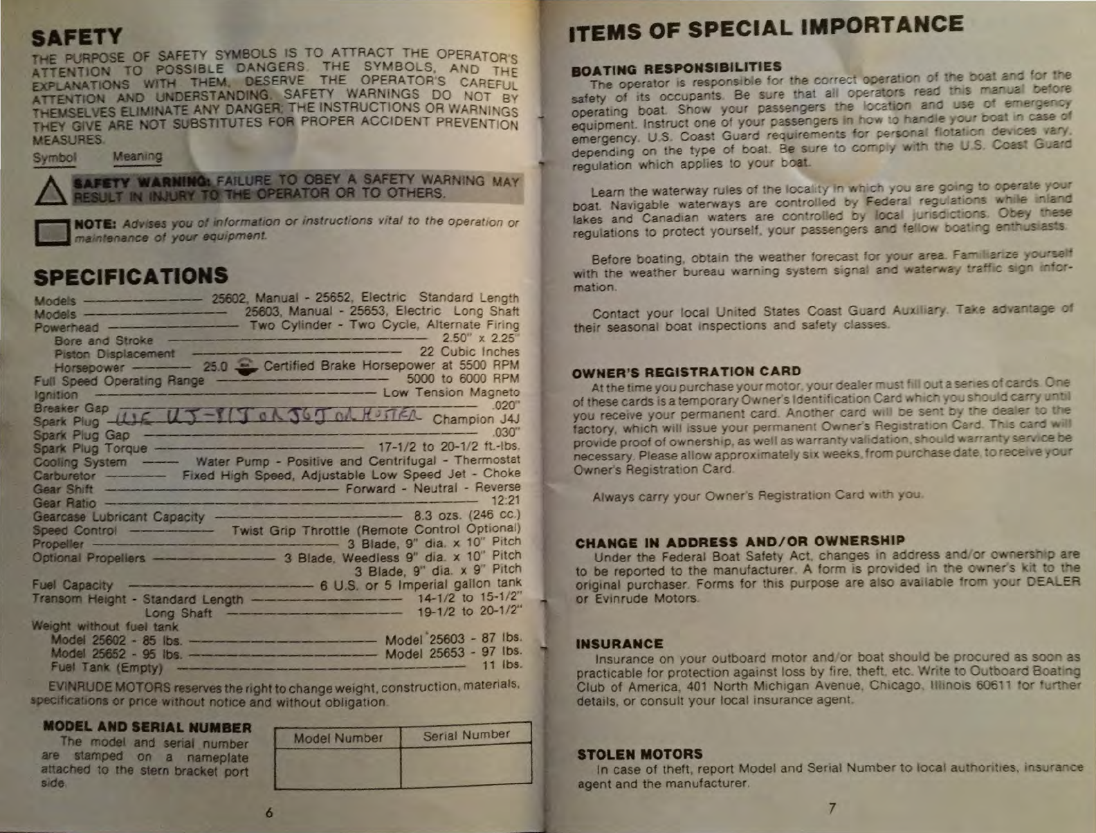
MANUAL
STARTING (CONTINUED)
0 Motor -Pull
chOJ..e
knob
all the
way
out
~~~~
Motor
_ Do not choke If
motor
fails to start
after
a few
pulls
on
the
starter handle, then use the chok.e.
D NOTE: A lock-out prevents starting
motor
in gear.
If
motor
will
not
crank,
reduce throttle to SHIFT positiOn and move shtft lever to NEUTRAL.
A
SAnTY
WARNIIIGt
ATTEMPTING TO MANUALLY START THE
~
JNE
WHILE
fN
GEAR
MAY DAMAGE PARTS OR CAUSE THE START
NSUTRAL
FfAnJRE
TO
BECOME INOPERATIVE. START ENGINE
SHJFT
LEVeR
lN.
NEUTRAL
POSITION.
""
~--
.ull
starter handle slowly until starter engages, then pull
forcibly
. Repeat.
1f
needed, until
motor
starts To prevent damage to starter assembly, allow
starter
cord
to
rewind before releasmg starter handle. When
motor
starts, push
choke m gradually until
motor
IS
runnmg smoothly. If
motor
does
not
start,
see
TROUBLE CHECK CHART.
Qcheck
to
see
that at least a ftne spray
of
water is
coming
out
of
the exhaust
rel1ef
outlets to assure proper water
pump
operat1on. See
COOLING
SYSTEM.
16
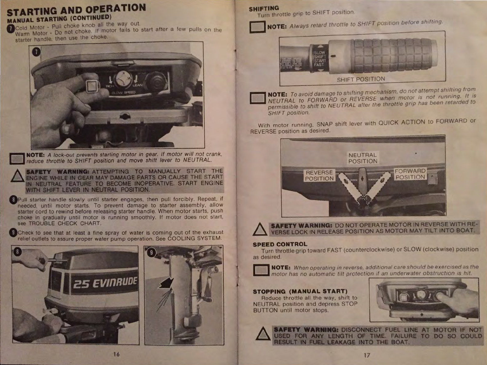
SHIFTING
. .
Turn
throttle
gnp
to
SHIFT
pos1t1on
0 NOTE:
Always
retard
throttle
to
SHIFT
p
osJ
tt
on
befo
re
shtft
in
g.
SHIFT
POSITION
0 NOTE:
To
avo1d damage to
shlftmg
mechan1sm.
do
not
attempt
shifting
from
NEUTRAL to FORWARD
or
REVERSE
when
motor
tS
not
runmng
.
It
IS
permtssible to shtft to NEUTRAL
after
the
throttle
gnp
has been
retarded
to
SHIFT posit1on.
With
motor
runnmg,
SNAP
shift
lever
with
QUICK
ACTION
to
FORWARD
or
REVERSE pOSition
as
des1red.
A
SAFETY
WARNING:
DO
NOTOPERATE MOTOR IN REVERSE WITH RE-
~
VERSE
LOCK IN RELEASE POSITION AS MOTOR
MAY
TILT
INTO
BOAT
.
SPEED
CONTROL
Turn
throttle
gnp
toward
FAST
(coun
t
erclockwise)
or
SLOW
(clockwise)
position
as
des1red
D NOTE: When operattng
tn
reverse. add1t10nal care
should
be
exercrsed
as the
motor
has
no
automattc
tilt
protectiOn tf an
underwater
obstructiOn
ts
l11t.
STOPPING
(MANUAL
START)
Reduce
throttle
all the
way
, sh1ft to
NEUTRAL
position
and depress
STOP
BUTTON
until
motor stops.
A
SAnTY
WARMING~
OISC.
ONNECT
FUEL LINE AT MOTOR IF NOT
~USED
FOR
ANV
LENGTH
OF
TIME. FAILURE
TO
00
SO
COULD
RESULT
IN
FUEL
LEAKAGE
INTO
THE
BOAT
.
17

- - '
·~.
. .
~
(
-#,
.'
...
-:.i~·
'
~
1;,
i..
~-,.>
't
'
.....
...,
ff
........
..,.,-
t.-
,..,_,..
moto1 covet'.
S..
REMOVING MOTOR COVER
U..
•
aJr
w...c::ft
to remowe.,..,..
ICtewt
attechmg
liNter.
Ute
a
518"
wrench to
~
~
~
....,.,...
loctwut
LeYer
Aaembly,
CautiOn -Lever
t&
........
MotOr
lhQll
d
be
toll
wj
c
nor
a ope•a+ g
Y.;t
~
A-::!1
• ';"..a!
rtJa1
~
eara!":~
can
be obt8 ned
by
p.ac
ng
an~
e alj, 1;9 roo
,:;
er
e•r.;
b·ac:t'~
pcx,
~#"
1
fl..,
constructu>n s
lJ
does
om
proYld€
811~
ate
c:
earar;-;e
~
'10~(
DEA\.£R
tor
()MC
acceHOrY
tr&
• g braclte1
' •
·,
..
~·{
• • ! ' •
,'".
...
/
' "
...
-:~~
. ' .
. .
.
.,.
;
·~
,.
' ' '
. . .
MOTOA
WILL
NOT
START, check for:
1,
Thfott..
grip
in
START
posit1on
and
thift
lever
in
NEUTRAL
position
2.
Fuel
in
tank
3.
Fuel
line
connector
property
attached
4. Fuel line
primer
bulb
at tank end
5 Carburetor primed (squeeze
pnmer
bulb)
8.
Fuel tank resttng
on
fuel lme
7.
Fuel hne clear and
not
kinked
8.
Cold
motor: Eng1ne
not
choked
sufficiently
8.
Warm motor: Engme over-choked
or
flooded (correct
by
pushing
in
choke knob, disconnect fuel hne at
motor, and cranking
until
cleared)
10. Fuel
pump
f1tter obstructed
11.
War
in fuel system
12.LooM
tpark
plug
leads
13.
Spark
plugs
carbooed, burned or
Wet
14
Incorrect
span
pfug
gap
(correct
gap IS
O.ooo")
15.
LOOM
sperk plugs, causing poor
compresston
(recommended
torque 17-112
to
20-1/2 ft.-lbs.}
18.
Recheck &tarting inetructtOM
MOTOR
WILL
NOT tOt.E PROPEALY
check
for:
1.
Carburetor
adjultment
tmpropetfy
set
2 Defective spatlt.
plugs
3
Improper
fue
m.xture
MOTOR
LOSES POWER
check
for.
1
Defectve
<Spark
p gs
2.
Fuel
pump
f
er
part1a 'I restriCted
or
fue
contam
'"'ated
3
Obs
ruct
on
at
wa~er
entake.
Coohng
system
not
operat
ng
properly
MOTOR VIBRATES EXCESSIVELY.
check
for
t Damaged
prope
'er
21
2
Carburetor
Improperly
adtusted
3 Loose
steer
og
fr
ct
on
screw
4 WeedS
on
prope
fer
MOTOR
RUNS, BUT MAKES
ITTLE
OR
0 PROGRESS
check
for.
1 Damaged
prope
er
2 Weeds
on
prope
ter
3 Sheared
dr
e
pm
If
th
1s
does
not
sofve prohterrl hen
contact
your
DEALER
STARTING AND OPERATION
COOLING SYSTEM
Water or cooling
1S
supplied by a water pump located above the gearcase. The
pump op rates
as
a diSplacement pump
at
low speeds
and
as
a centnfugal pump
at
h1gh
speeds.The thermostat maintatns consistent operating temperatures through-
out the entire range
of
motor operation. tncreasmg motor life and eftlc1ency.
~
NOTE:
For
contmuous
operatiOn m waters
contammg
excessive
amounts
of
&:.....I
:;nit,
sand
or
stlt, we
recommend
an
OMC
accessory
chrome
plated
water
pump
J(lt.
See
your
DEALER.
SHALLOW WATER OPERATION
Avoid operating in shallow waters. If necessary, proceed at slow speeds until
deeper water is reached.
The reverse lock is designed
to
release automatically from the LOCK position
if
an
obstruct1on
is
hit
wh1le
going forward at normal running speeds. The reverse
lock may not release from the LOCK pos1tion when runnmg
at
slow speed.
When
running
1n
shallow water, place the reverse lock in RELEASE position which
allows the motor to ''kick-up" more easily if
an
obstruction
is
hit. If
an
obstruction
is hit, retard the throttle immediately and stop motor. Check lower unit for
possible damage.
If motor vibrates excessively after striking
an
underwater obstruction, it may
ind1cate a damaged propeller. Operate
at
slow speed. Replace damaged propeller.
See
PROPELLER AND DRIVE
PIN
REPLACEMENT.
D NOTE:
Operating
motor
with
lower
unit
dragging
on
bottom
will
result in
propeller
wear,
and
cause
sand
to
be
forced
into
water
pump
and
may
cause
damage
to
the
pump.
FUEL ECONOMY
The
economy throttle pos1tion
can
effect fuel savmgs depending
on
boat load
and hull
des1gn.
When
boat reaches top speed, slightly back off on throttle from
FULL
SPEED
position. This
w1ll
result in a fuel saving without noticeable loss in
speed
.
OPERATING IN WEEDY WATER
Weeds
on the propeller will cause motor to vibrate. Run at reduced speed
when
weeds are thick. Stop motor, clear propeller and water intake completely of
weeds
as
often
as
necessary before resuming speed in clear water.
SALT WATER OPERATION
Your motor
IS
built for operation in either fresh
or
salt water. If motor
is
to re-
mam
on boat during long periods of inoperation, tilt gearcase out of the water
(except during freezing temperatures). When removing motor from water, allow
cooling system
to
drain thoroughly. by placing motor in upright position. Internal
flushing
is
unnecessary.
We
recomrT1'end
that motor exterior
be
rinsed with fresh
water
and
wiped
off
with a lightly oiled rag.
OPIRATINO
IN
FREEZING WEATHER
. In freezing temperatures. keep the lower unit submerged in the water at all
ttmes
Th1s
will avoid freezing and possible damage to the water pump
or
other
parts
o_f
the motor. When removing the motor from the water, keep the motor in
an
upnght pOsition until water is completely drained from the cooling system.
ANTI..CORROSION PROTECTION
It
is.
importantespecially in salt water areas to protect the lower
unit
from galvanic
corros1on. Your dealer has accessory kits ava1lable which provide additional pro-
tection under adverse conditions
22
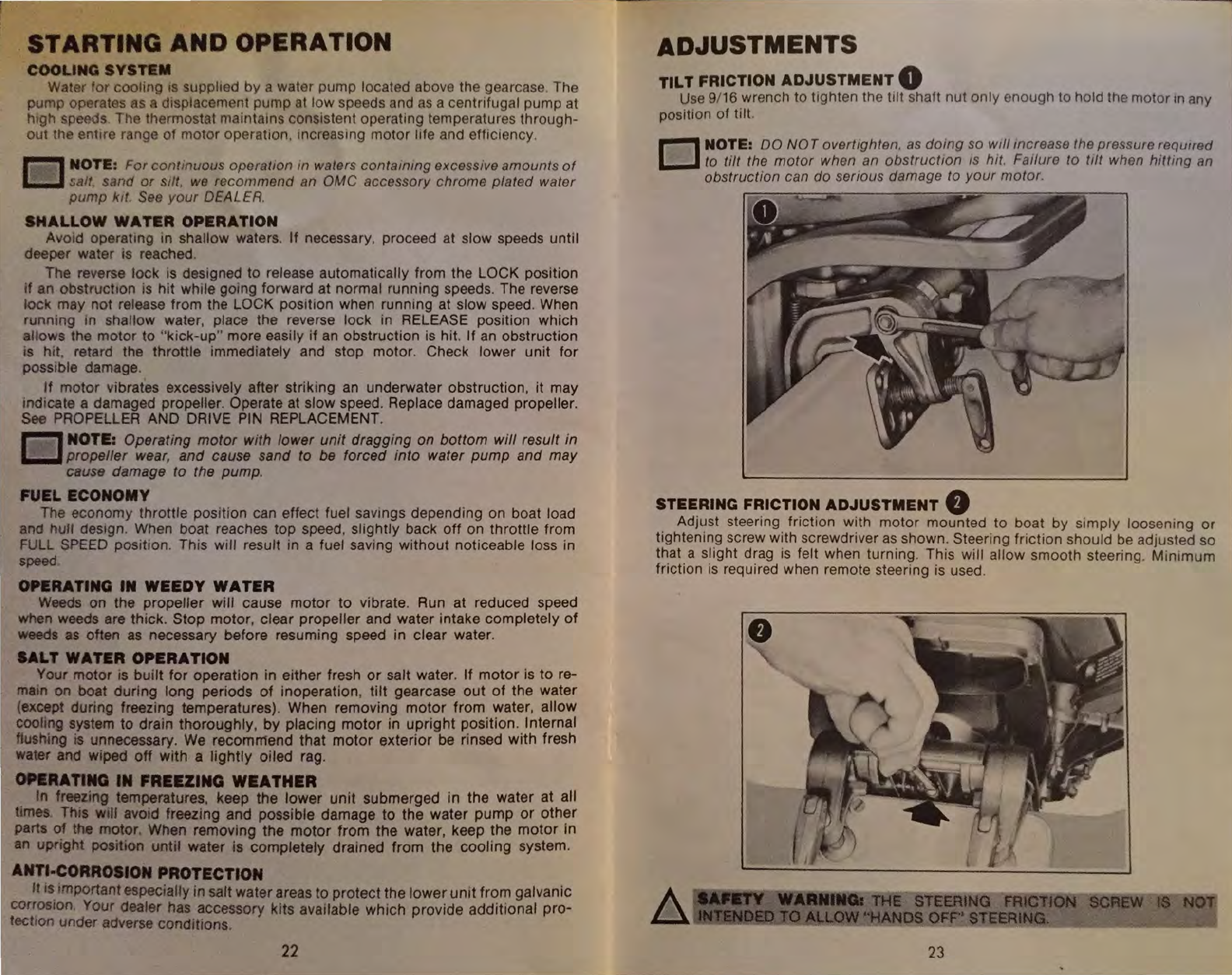
ADJUSTMENTS
TILT FRICTION ADJUSTMENT 0
Use
9/16 wrench to tighten the tilt shaft nut only enough to hold the motor
rn
any
positiOn of tilt
D NOTE:
DO
NOT
overtighten.
as
domg
so
wt/1
tncrease the pressure required
to
tilt
the
motor
when an
obstructton
ts
hit
. Failure
to
tilt
when
hitting
an
obstruction
can
do
serious
damage
to
your
motor
.
STEERING FRICTION ADJUSTMENT 8
.
Adj~st
steering. friction w!th motor mounted to boat by simply loosenmg or
t1ghtenmg
screw
w1th
screwdnver
as
shown. Steering friction should
be
adjusted so
t~at.
a s!ight
d~ag
is
felt when turning. This will allow smooth steering. Min1mum
fnct1on
IS
reqUired when remote steering
is
used.
WARIIIIIGi
THE
STEERJNO
FRlCT.JON
SCREW
Del)
TO
ALLOW
''HANDS
OFF''
STE
=
ER
;..;:.;
l
:.:..;:
N=G
::....
·
-~----_..,;
23
ADJUSTMENTS
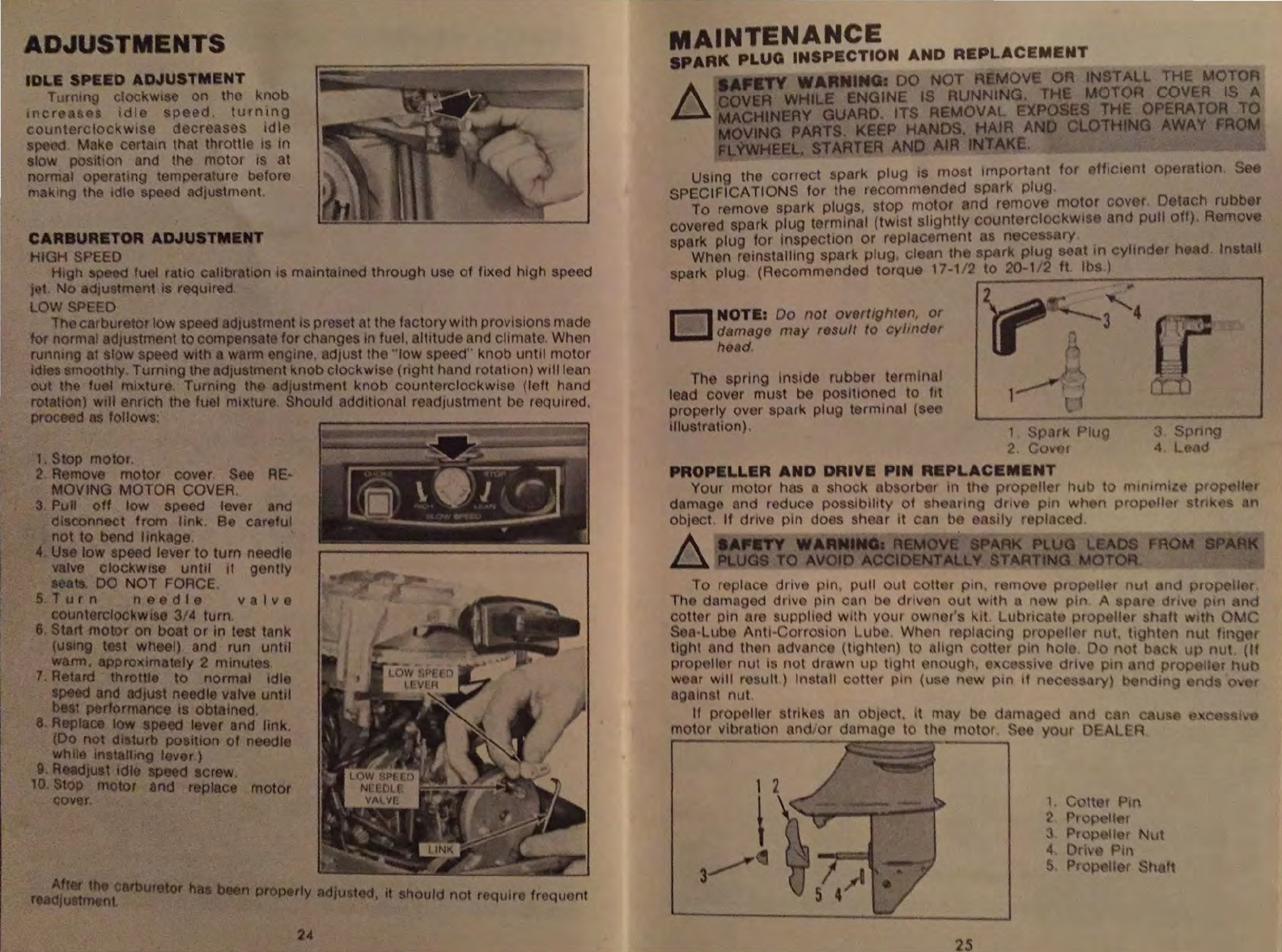
IDLE SPEEO ADJUSTMENT
Turnmg clockwt on thn knob
mer
a. es
tdl
speed,
turntng
toltnterclock
wi~e
deere
ses
''11
,
d
Mnk
orttun that throttl
Is
in
slow p sttion nd th motor 1 at
normal ·) rattng tamp raltH< b fort
m,
king th tdlo sp d AdJUStmont.
CARBURETOR ADJUSTMENT
HIGH SPEED
Hrgll so d fu I ratio calibration 1 mainturn d through use of fixed htgh speed
jl
t No adtustm nt is reqwr
d.
LOW
SP
·ED
iho
car
bur tor low
sp
ed
adrustment
ts
pr
set t th factorywith provisions made
t r normaladju tmcnt to cornpensat for changes in fuel.
nltitu<Je
and chmato
Whe-n
runnmg t slow sp d with warm nglne.
dJust
th
"low
speoo·· knob unttl motor
tdle rnoothly. Turnmg th
adJliStrn=-nt
tmobclockwis (nght hand rotnttonl will I an
out the tu
.I
mtxtur . Turning th adjustment knob count rclockwts< (left hand
rotation)
wtll ennch th
lu
I mtxture. Should dditton I r AdJustment b r qutrod,
proc d
as
follows:
1.
Stop motor.
2 R move
motor
cover. s AE·
MOVING MOTOR COVER
3
Pun
off
low sp
ed
lever and
dtsconnect from linK. Be car lui
not to b nd lmkage.
<t
Us
low spa d lever to turn ne .dl
valve cloci<Wis unttl
1t
g ntly
se.ats.
DO
NOl
FORCE
5
Turn
ne
dle
valve
counterclockwise
3/~
turn.
6 Start
motor
on boat
or
in t st
tMk
(U&tng
t t
wh
el)
and
run
unttl
warm, approximately 2 minutes
7.
Retard throttto to normal tdle
speed
and
adJUSt
n edle valv unttl
best performance tS obtamed
8 Replace low
spe(KI
lever and link.
(Do not
dt
turn
positton
of
neodt
Whll tnstalling lever.)
9.
ReadJust
1dlo
sp d screw.
10.
top motor
&ncs
replace motor
cover
Aft
r th Carburetor
ha
b
r;
dju
~ot.
MAINTENANCE
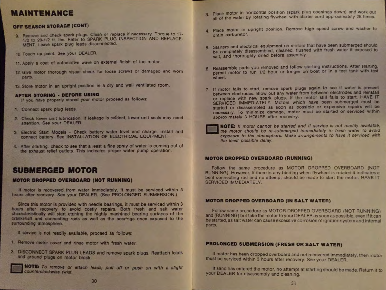
SPARK PLUG INSPECTION AND
REPLACEMENT
SAFIITY WARNING:
DO
NOT
EMOV
OR
INSTALL THE MOTO
A COVER WHILE ENGINE IS RUNNING. TH MOTOR COVER IS A
~
MACHINERY GUARD. ITS REMOVAl.. EXPOSES THE OPERA
TOR
TO
MOVING PART . KEEP HAND ,
HAIR
AND CLOTHING AWAY
fROM
FLVWHEEL. STARTER AND AIR INTAKE.
0 NOTE: Do
not
overtighten,
or
damago may rosutt to
cylmd
r
he
d.
Tl1e
spring in id rubber torrmnnl
lead
cov~
r must b poslt1oned to ftt
prop rly over spMk plug t rmtnal ( e
tllu tr tton).
4
5
ffic:•
nt
op ·r tton. S
r h d tn tall
Spnng
L d
24
~------------------------------------------------------
--
----------------------------__£
25

MAINTENANCE
LU8RICA
TIOM
TYPES
OF
LUBRICANT Contact your
DEALER
for
OMC
Lubricants
OMC
SEA·!.UBE'
ANTI-CORROSION
LUBE
J
TUBE
GREASE
GUN
•
OUTBOARD
LUBRICANT
(OIL)
OMC
SEA-LUBE'
LUBAIPLATE
PREMIUM
BLEND
777
GEARCASE
LUBE
0
LUBRICATION
PICTURE
SYMBOLS
GEARCASE
LUBRICATION
A
Remove
oil drain/fill and oil level plugs from side
of
gearcase. With motor
in
normal running position, allow oil to drain completely.
To
refill, place tube of OMC SEA-LUBE' Premium Blend Gearcase Lube in
dramlfill hole. With motor in normal running position, fill until lubricant appears at
oil
level
hole.
See
SPECIFICATIONS for gearcase capacity
~
NOTR:
Recommended lubricants which have been formulated to protect
J::U
against damage to bearings and gears must
be
used,
as
extensive damage
can
result from improper lubrication.
Install oil level plug before removing lubricant tube from oil drain/fill hole.
Ora
nlfill
plug
can
then
be
securely installed without oil loss.
If
the
proper tube or filler type can
is
not available, install drain/fill plug.
Slowly
fill
gearcase through oil level hole allowing trapped air to escape. Install
plug.
LUBRICATION POINTS
OShifter Starter Lockout
QCarburetor, Choke
linkage
and
Cam
8 Shift lever Shaft,
Reverse
Lock
and
Swrvel
Bracket
8 Clamp
Screws
0 Motor Cover Latch and Starter
Neutral Lockout
0 Throttle Shaft Bushings and Gears
E)Throttle
and Shaft
Linkage,
Electric Starter
Frequency of Lubncation •
Fresh
Water-60 Days • Salt Water-30 Days (Some
areas
may
require more frequent lubrication)
C)Gearcue
Change
after first
20
hours of operation and check after 50 hours
of
operation.
Add
lubncant
if
necessary.
Drain
and
refill every 100 hours
of
operation
or
once each season whichever
occurs
farst.
·rrademark
26
STARBOARD
VIEW
PORT
VIEW
27
MAINTENANCE
OFt=
SEASON
STORAGE (CONT)
9 Remove and check spark plugs. Clean
or
replace
1f
necessary Torque to 17-
112
to
20-1/2
ft. lbs. Refer
to
S~ARK
PLUG INSPECTION
AND
REPLACE-
MENT. Leave spark plug leads disconnected.
10
Touch
up
pamt. See
your
DEALER.
11. Apply a coat
of
automotive wave on external fintsh
of
the motor.
12
..
G1
ve
motor
thorough visual check
for
loose screws
or
damaged and worn
parts.
13.
Store
motor
In an upright position in a
dry
and well ventilated room.
An'aR
STORING • BEFORE USING
If
you have .properly stored
your
motor
proceed
as
follows:
1.
Connect
spat1(
plug
leads.
2.
Check lower
unit
lubrication. If leakage is evident,
lower
umt
seals
may
need
attention. See
your
DEALER.
3. Electric Start Models -Check battery water level and charge. Install and
connect battery. See INSTALLATION OF ELECTRICAL EQUIPMENT.
4. After startrng,
check
to
see that a least a fine spray
of
water is
comi~g
out
of
the exhaust relief outlets. This indicates
proper
water
pump
operation.
SUBMERGED MOTOR
IIOTOR
DROPPED
OVERBOARD
(NOT
RUNNING)
If
motor
is recovered
from
water immediately,
it
must
be serviced
within
3
hOUrJ
after recovery. See
your
DEALER. (See PROLONGED SUBMERSION.)
Since thiS
motor
is provided
with
needle bearings.
it
must
be serviced
within
3
hours after reccwery to avoid
costly
repairs.
Both
fresh
and
salt
water
characterlstlcalfy will start
etching
the
highly
machined
bearing surfaces
of
the
crankthaft and
connecting
rods
as
well
as
the
bear:'lgs
once
exposed
to
the
surrounding atmosphere.
If
eervice
Is
not
readily available, proceed as follows:
1
Remove
motor
cover
and
rinse
motor
with
fresh water.
2.
OlSCONNECT SPARK PLUG LEADS
and
remove spark plugs. Reattach leads
and
ground
plug•
on
motor
block.
r=l_,..,
To
remove
or attach
leads,
pull
off
or push
on
with a slight
IW
counterclockwiH
tw11t.
30
Place
motor
in
horizontal
position
(spark
plug
openings
do~n)
and
wo~k
out
3· all
of
the water
by
rotating flywheel
w1th
starter
cord
approxtmately
25
t1mes.
Place
motor
in
upright
pos1t1on.
Remove
h1gh
speed screw and washer to
4. drain carburetor.
Starters and electrical
equipment
on
motors
that have been subm.erged should
5· be completely disassembled. cleaned, flushed w1th fresh water
tf
exposed to
salt, and
thoroughly
dried before assembly.
Reassemble parts
you
removed and
follow
starting
ms~ructions.
After
s~arting.
6· permit
motor
to
run
112
hour
or
longer
on
boat
or
tn
a test tank
w1th
test
wheel.
If
motor
fails
to
start, remove spark
plugs
again
to
see
if
water
is
p~esent
7· between electrodes.
Blow
out
any
water
from
between
electrodes
and
remstall
or
replace
with
new spark plugs.
If
the
motor
still
fails
to
start. HAVE IT
SERVICED IMMEDIATELY.
Motors
which
have been su.
bmerged
mu~t
be
started
or
disassembled as
soon
as
possible
or
expenstve repa1rs
Wll!
~e
necessary.
To
minimize
damage,
motor
must
be
started
or
serv1ced w1thm
approximately 3 HOURS
after
recovery.
~
NOTE:
If
motor
cannot be started
and
if
semce
is
not
read1/y
availabf~.
t....J the
motor
should
be re-submerged tmmediate/y in fresh _water to
avo_td
exposure to the atmosphere. Make arrangements
to
have tt servtced wtth
the least possible delay.
MOTOR
DROPPED
OVERBOARD
(RUNNING)
Follow the same
procedure
as
MOTOR
DROPPED
OVERBOARD
(NOT
RUNNING) However,
if
there is
any
bmding
when
flywheel
IS rotated
11
indicates
a
bent
connecting
rod and
no
attempt
should
be made
to
start
the
motor
HAVE
IT
SERVICED IMMEDIATELY.
MOTOR
DROPPED
OVERBOARD
(IN
SALT
WATER)
Follow same
procedure
as
MOTOR
DROPPED
OVERBOARD
(NOT
RUNNING}
and (RUNNING}
but
take the
motor
to
your
DEALER as
soon
as
possible
even
ifit
can
be started, as salt water
can
causeexcess1ve
corrosion
of
1gn1tion
system
and
internal
parts.
PROLONGED
SUBMERSION
(FRESH
OR
SALT
WATER)
If
motor
has been
dropped
overboard
and
not
recovered
immediately,
then
motor
must be serviced
within
3
hours
after
recovery
See
your
DEALER.
If sand has entered
the
motor.
no
attempt
at
startmg
should
be
made
.
Return
1t
to
your
DEALER
for
disassembly
and
cleanmg.
31
;,I
0~vvvov~~~~
WARRANTY
SERVICE
t
the
autnonzed
E,·,nrude d 1 r I
rom
'
i<l
nom
tne
out-
To mak a claim under \1\arranty.
conta~e
nearest
authonzed
Ev1nr:.soe
deal
r R m moer.
your
t>Oard
motor
WB$
Ollg,na~
p~r/;~~a~o
~·n°!u'thor
zed E
mruoe
dealar
Wliit'1•n
th
wa
ranty
period, and
outbOard motOr must
r'be
rrformed
by
an authonzed E
nrvde
deal Proot
of
purcrut Will
be
re-
a
II
w rranty
....
orEk
musd
dpeealer
to
substanhate any warranty
claim
U e
your
Ev•nrude
own
a
q lr d by the
VIOrU
e
r~•stratlon
card to establish
proof
of
purchase
EXAMPLES
Of
ITEMS
NOT
COVERED BY WARRANTY
Prov•s•ons
of
the Warranty1W8
•1
1
1
s~gt
~~ft~g
tfhe
warranty
oe
.
nod
such
carburetor
or
•gmuon
Normal
serv1ce
reqwremen s '
,.
1
mp
ad1
ustment or
repa1r,
~;
:ve:rr
8
~fd
•ag~~~~~~n~op~~;m~J·
~~~~:~
~
~tu
of
u !
11
pans
~~~~~~d·~~~~,:~ub)ect
to m1 use. neglect.
neE~~?~r;.ce,
cc•~
0
nt(;
or,
u lyd
'g'
~~
~::'e~r
~~
''"'"·
OutbOard motors that hav been alter··d
or
mvu•
'""'
so
performance or duraolltty or
to
change
thear
Intend~
llSe
tes
"""
h
ar
tth r tn
om~t·i>l•
With
R
a•rs
made necessary by the use
of
p11n
or
ac"
or
•
the
o~tboard
motor
or
adversely affect
_rts
operation.
pedrfor_!ll•"ft~
~e
~~r~,~~~rrons
rn
it\o E nru
Outboard motors not operated or m tnt
m<'d
m acoor an..e w
Owner's·Operator's Manual
Twenty-hour check-up. servtce check-up. tune-up,
or
cllagnosts
Notmal cleantng,
adJUSting
or
replacing
ol
:.p rk
ptug
m
the_
oo.tti'>O
rd
m tor
Per~od1c
checktng or addtng
of
oil
to the g arc se
of
u-,
oumoard
motor
Expense of returmng lhe
outbollrd
motor
to the d aler
nd
exp
n
o!
returntng
tne outbo
r.d
motor back to the own r removal
of
the
outbol!rd
motor
from
a poat nd r tn:.t
llauon.
rne
nlc
travel umo, and tn-and-out
..
of.l
....
aler charg s
Tho
wammty
applies
only
to the OrtQtnal retatl
purchA~
r.
OWNER'I 08LIGATION AND
RISPONIIBILITV
Normal matntenanco servtce and rcplac
ment
ot
servtce It m
lit<
th r
spon
ol)lhtr' 01 tit
o-....n
as
such
11re
not con tder d daf ct
on
maten I or wo1km n
h•O
w•thtn
tt
t
rms
01
tn
wan
nty
Individual op rating habits and us
g11
contnbute
trJ
tn n d tor
rn11111t
nan
•
tn
obtaining maxtmum ervtre and
satt:~tacuon
from
your
n w
[vtnrut1
prtnctpal servtce and rttpl .em nt Items
re
dtl:IC!Ihed
a follows
PROPEA
MAINTfNANCI'
AND
CARf
See your F.vtnrude
!1
al r tor
pll
1 matntenanc nu
'-
re
Of
your outbo
rd
muwr
PrOJlllr
111
tnt naoce
t~nd
,,
til
w111
as
111
111
t..
eplno
your
ovu•
II
Qpe•llllng
osl
at
a mtotnHIIn
1111
toll
dllli1!J
s
ill
lhol<
a
lihtHil•l
HtJtll
,
...
EVIHRUDE DEALER SERVICE
20
MOUR CMI.CK
1'h1s
is
important. After the first
20
hours of operat1on, we
reco~mend
.that you
return your Evinrude outboard to your DEALER for mmor mspect1on and
adjustment (if necessary).
20 Hour Check Includes:
Dram, flush & refill gearcase using OMC Sea-Lube· Premium Blend Gearcase
lube
2. Torque cylinder head and spark plugs
3 Adjust carburetor
4. Check propeller
5. Check timing and ignition
6.
AdJust
remote control and linkage (where applicable)
This
is
an
opportune time to discuss with your DEALER any questions on your
outboard motor which have arisen in the first
20
hours of operation, and establish
a routine preventative maintenance schedule.
The
20 hour check will
be
performed at local DEALER rates and paid for
by
the owner.
REPAIR
SERVICE
Should you
be
in need of service
an
Evmrude dealer
is
not far. He usually carri
es
a
complete stock of spare parts. Always take your motor to
an
authori
zed
Ev
inrude
dealer, he has the knowledge, experience and special tools to take care of any
problem that may ari
se
.
If
you
are
away from your home waters, take your motor to
the nearest authorized
Ev
inrude dealer. Names and addresses can be found m
your
Evinrude Dealer
Serv1ce
Directory or your telephone directory under "Outboard
Motors." If you are in your home waters, take your motor back to the selling dealer
-he knows you and your equipment.
FIND YOUR
NEAREST
EYINRUDE
DEALER
IN THE
YELLOW
PAGES
r)l
~
·t
,.
~-
'-""
_____
.....,
REPLACEMENT PARTS
DEALER
PHONE NO.
IN
ORDER
TO
ASSURE RECEIVING
PROPER
SERVICE PARTS ALWA
YS
PROVIDE THE FULL MODEL & SERIAL
NUMBERS
OF
YOUR
MOT
OR
Be
sure
that only factory approv
ed
parts de
s1
gned for your motor are used
as
rep
l
acements
Your authonzed
Ev
inrude dealer c
an
be
re
lied on as a source of
genume
parts Replacement parts not of our manufactu
re
ha
ve
notbeen approved for
use
on
Evmrude motors
EVInRUDE
SERVICE
34
OF
THE
ROAD
FOR
OUTBOARDING
•
Keep
clear
of
saolmg
craft
and
rowboats.
Yoeld
right
of
way
to
slower
boats
.
e
Always
keep
to
the
r1ght
•
•
Do
not
use
your
motor
near
sw1mmers
or
skin
divers.
•
Learn
the
11
gn
language
of
the
variOUS
buoys
and
warning
signals.
These
are
yo
ur
nauttc•l
traffic
stgns,
posted
for
your
saf•tY
l!lnd
conven1ence.
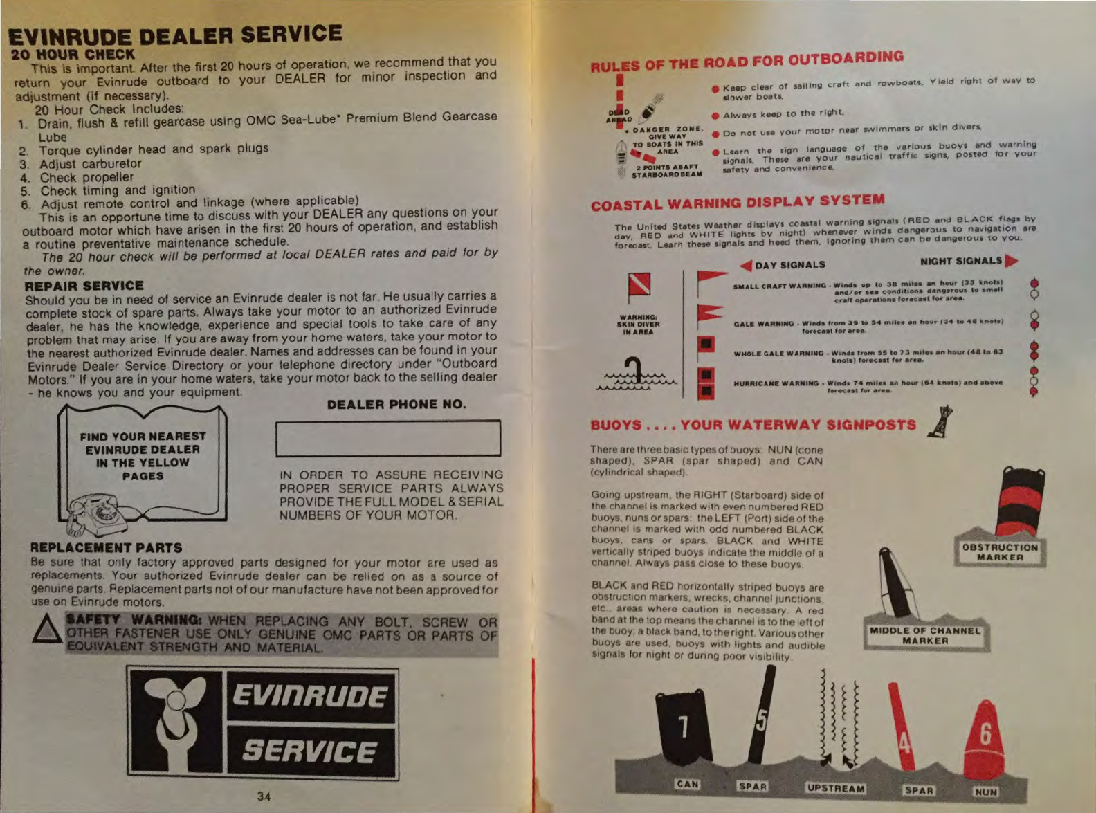
COASTAL
WARNING
DISPLAY
SYSTEM
T
ha
Un
it
ed
S
ta
tes
Weat
her
displays
coastal
warning
si
g
nals
(RED
and
BLACK
flags
bY
day,
RE
D and
WH
I
TE
lights
by
night)
w h
enever
w
&n
d t
dangerous
to
navogatoon
are
fo recas
t.
Learn
these
signals
and
heed
them.
l g
nonn
g
them
can
ba
dangerous
to
you.
~
DAY
SIGNALS
NIGHT
SIGNALS
.
,.........
SMALL
CIIAn
WAfii:NUfG
~
W•n
4 a " " to 3 a
m•l
• • a " hour
(33
Ill
not
e)
I
.....
,.,.
au
c.ond lttofta 4
•rt•ero
ua
to
aM
all
cf
afl
op
er
a u
ona
fo
roc:"t
t
or
ar
ea
.
WAIItNINO:
SIC
IN
DIYIIIt
IN
AlltiA
F
GAU
WAIININO . W
l""'
o
,,..,.
3e
to
54
"'''••
an
,...,,
(3
4 t o 4 8
kno
t• I
t
oroc•
at
f
or
ar
ea
·~
WHOLI:
GALl
WARNING
. Wtn4a f
ro
m
aS
to
13
l'l'ltlol
•n
hou
r (4 8 to e
-3
kn
ot
s ) f
orocaat
,
.,
o
r•
•·
..............
"'
HU
..
IIU
C
ANI
WA"M
INQ • W t
nd
a
74
mtl
ea
aft
h
4Kir
~._.
tu
•ataf
an
d
aoo
v e
t
er.-c
aa
t for a
rea
BUOYS
••••
YOUR
WATERWAY
SIGNPOSTS
1
There arethree
basoc
types
of
buoys
NUN
(cone
shaped)
. SPAR
(spar
shaped)
and
CAN
(cyltndrocal shaped)
Goong upstream. the
RIGHT
(Starboard)
sode
of
the channel is marked
w1th
even
numbered
RED
buoys nuns
or
spars the LEFT (Port)
sode
of
the
channel
os
marked
woth
odd
numbered
BLACK
buoys cans
or
spars
BLACK
and
WHITE
vcrtocally
~tnped
buoys tnd1cate the moddle
of
a
channel Always pass
clo'Se
to
the e
buoys
.
BlACK
and RED
honzontally
stnped
buoys
are
obSiructlon markers, wreck'!, channel 1
unchons
,
<>tc
areas
whP.re
caut1on
IS
nec~sary
A red
band at tho top means thP channet1s
to
thP.Ieft
of
the buoy, a black band, to the
nght
Vanous
other
buoys arc used. buoys
woth
hghts
and
audobleo
sognals f
or
ntght
or
dunng
poor
vosobohty
OBSTRU
C
TION
MARKER
MIDDLE
OF
CHANN
EL
MARKER
EVInRUDE
firstin
outboards
EVINRUDE MOTORS
4143
N
27TH
STREET
Mil
\VAUKEE WIS
53216
DIVISION
OF
OUTBOARD
MARINE
CORPORATION
ITEM
NO.
5167 PART NO. 207547 5/75
EVInRUDE
SERVICE
*
X
LITHO
U.S.A
This manual suits for next models
4
Table of contents
Other Evinrude Engine manuals


