________________________________________________________________________
Gjellerupbakken 32, 7400 Herning Denmark Tlf: +45 9626 8046
www.vitusaudio.com
supply, as used in our RP/RL-100 preamplifiers. However with the development of the current true
balanced preamplifier, SL-100, we found that the micro dynamic performance and speed was
limited, unless using extremely powerful batteries (4x 60Ah for the SL-100). This, combined with
the future lead free production regulations, resulted in a complete change in our strategy in not
using batteries in any new developed products – and directly lead to the development of our current
shunt regulated power supply used in both SP & SL-100.
With this change in strategy, and the new extended topology used in the new preamplifiers, (which
includes an optimised input stage for even better linearity), we felt that optimising the SM-100
design was in place.
SM-101 differences vs. SM-100
Mechanical differences:
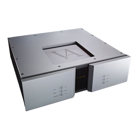
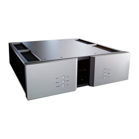
1. Heat sinks – the side handles and heat sinks on the SM-100 have been replaced with one
massive heat sink resulting in much better heat dissipation.
2. Ventilation in both top and bottom – this together with the extended heat sinks – gives
overall better lifetime and lower chassis temperature.
3. Handlebars on the rear panel integrated in the bottom, which optimises comfort when
carrying the units, and minimises stress on the rear plate.
4. Top plate extended to cover and protect all connectors on the rear plate.
5. Front display window is wider and now made of real glass instead of plastic.
Electronically differences:
1. Input stage from the SP/SL-100 preamplifiers used – this results in better linearity overall.
2. Further input protection added, which grounds unused inputs.
3. Overall signal length decreased by 70%
4. Dual rail power supply (it now runs of +/- supply which is the traditional topology)
5. 188.000uF instead of 94.000uF in the main power supply.
6. Further optimised transformer for even lower magnetic influence of electronics and even
less voltage drop (from open to short).
7. DC servo’s optimised further for typical max. DC error of +/- 10mV.
8. All amplifier stages work spots optimised for achieving the best possible result with the
current topology.
9. Bi cabling allowed via extra set of binding posts.
