Vivax Metrotech vLoc3 Series User manual

On/Off key
Frequency select
Info = Volume, Volts, Ohms,
multi-frequencies, LCD
contrast, frequency menu
Reduce output
Increase output
Signal overload - When the receiver is too close to the
inductive operated transmitter or a power transformer.
Shallow cable - When the cable is possibly less than
6-inches deep. Proceed with caution!
Swing alert - When excessively swinging the receiver. This
could result in misleading information.
Overhead cable - When the signal is mainly radiating from
above distorting the below ground signal.
Transmitter Keypad (Loc3 series transmitters)
Warnings - Are audible sound with a vibration of the handle.
Warnings can be activated or deactivated in the user menu.
Locating cables and pipes**
Passive location 60Hz / Radio / CTV)
(No compass available / Only peak and omni direction mode)
Switch on the vLoc3 series receiver.
Select the frequency with the "f"-button. (If the desired frequency
is not preset, switch to the user menu by pressing and holding
the "i"-button and choose it in the sub-menu "frequency". Press
the "Enter" button to highlight it. Go back with a short press on
the "i" button.)
Hold the receiver vertically and adjust the sensitivity by pressing
the “+” / “- ” buttons so that the bar graph shows a signal.
Continue locating in a grid across the area, see illustration (a) below.
Determine signal maximum by carefully moving the receiver back
and forth. Adjust the sensitivity again with the “+” / “- ” buttons.
Continue to locate the position of the line.
When locating in 60Hz or with a transmitter: Display depth / signal
current with short pressure on the "i" button or permanently in the
upper left display area.
1.
2.
3.
4
5.
6.
7.
1 3
4 5
21
2
3
4
5
(a) (b)
Power 5031dB
94.4
94.4
Power 5031dB
12.1
Power 5031dB
Switch on the transmitter and select the desired frequency
with the "f" button (If the frequency is not preset, use the "i"
key to access "frequency selection" in the menu and mark the
desired frequency with the "f" key. Press the "i" key to return.
Always select the lowest possible frequency to minimize coupling
to other lines.
Set the output power accordingly. (less is more)
From this point on, follow points 1 through 6 of the Passive
location 60Hz / Radio / CTV section of this document.
1.
2.
3.
Connect the transmitter with the supplied connection leads. Connect
the red wire to the target conductor and the black wire to ground.
The ground stake should be at a 90oangle to the target line if
possible. To reduce signal interference, there should be no other
lines (if possible) between the ground spike and the target line.
Active locating
Direct connection**
Connect the signal clamp to the transmitter and place it around the
corresponding target line.
Then follow points 1 - 3 from the Direct connection section of this
document.
Signal clamp** (Frequencies above 8kHz):
1
2
3
4
5
6
On/Off key
Reduce sensitivity (scroll up when in the user menu)
Frequency selection
Increase sensitivity (scroll down when in the user menu)
Short press = Change between Peak, Null, Sonde, etc.
Long press = Change operational screen
Short press = Enter information screen (Depth/Current/GPS)
Long press = Enter user set-up menus
1
2
3
4
5
6
7
8
Pushbutton keypad & display
Model & Serial numbers
Battery retaining clip
Battery compartment - Li-ion
or Alkaline battery packs
Mini-USB Port for data transfer
and firmware updates
Battery compartment cover
Accessory socket and
charging port
Bluetooth module expansion
port
vLoc3 Series Receivers - Feature and Options
Receiver Keypad
vLoc3 Series Quick guide* V1.0
(vLoc3-Pro, vLoc3-5000, vLoc3-ML)
1
2
3
4
5
6
78
1 2 543
6
www.vivax-metrotech.com
1 2 3P/N: 4.04.000204
Depth and current readings
Target line
Lines of confidence (closer these are to the target line
indicates more confidence)
Arrow indicates direction to move towards line.
Vivax-Metrotech Corp. (Headquarters)
3251 Olcott Street, Santa Clara, CA 95054, USA
T/Free: 800-446-3392 Tel: +1-408-734-1400 Fax: +1-408-734-1415
Visit us at www.vivax-metrotech.com to view our full product line and worldwide locations.
1
2
3
4
5
6
7
8
Percentage signal strength
Peak level indicator
Gain setting
Bar graph signal strength indicator
Signal direction (SD) forward/backward arrows
Compass line direction indicator
Left/Right direction to target line indicators
Frequency selection
1
3
4
5
6
7
Frequency selected
Vertical distance to target
Horizontal distance to target
Scaling (adjust with +/- keys)
Shows plan view of target
Cross section view that shows vectors to target
1
3
4
5
2Frequency selected
Plan View (vLoc3-Pro user manual page 13)
Shows a picture as if you were viewing the line from above the ground.
Advantages: Automatic gain adjustment; easy finding/routing of lines with
the 3D mode.
Advantages: Automatic gain adjustment; line depth is permanently measured,
even when running offset to the line.
Vector Screen (vLoc3-Pro user manual page 12)
Shows a cross sectional view through the ground.
8.19kHz
1.43m
1.86m
0 2m
85.6mA
3
21
6
7
4
5
14’5’’
4
3
2
1
12.9mA 32.8kHz
5
14’5’’
12.9mA 32.8kHz
Signal current
2
Classic locate modes (vLoc3-Pro user manual page 10)
Available modes: peak, peak with arrows, null, broad peak, delta
null, omni direction.
The individual modes within the classic view can be changed by a
short press (<1 sec.) on the "Enter" button. If a mode is not visible
or not desired, it can be switched on or off in the user menu (long
press on the "i" key / classic display / selection with "Enter" key).
Locate Screens**
For all subsequent locating views, except Transverse Graph
and Sonde Mode:
The distortion level is displayed on the bar graph.
Green = low interference, Blue = some interference, and Red = high
interference level, treat the locating results with caution.
NOTE:
Locating views (classic, vector, plan view, transverse graph, and
sonde can be changed by a long press on the "Enter" key
(approx. 2 seconds).
Antenna
configuration:
Place the transmitter (without connection leads or clamp attached)
on the ground with the handle in the direction of the cable. Do not
place the transmitter on manhole covers, or other metallic objects
as the signal will not be able to penetrate them. When locating,
maintain a distance of at least 50ft from the transmitter, otherwise
the airborne signal from the transmitter will be located and not the
target line. Now follow points 1 through 3 in the Direct Connection
section of this document.
Induction** (Frequencies above 8kHz):
50ft
(20m)
dd
0.39m
18.3
17dB 116mA
SD-USA
3
21
4
567
8
Peak
Null
Delta-Null
Peak with arrows
Broad peak
Omni direction
Peak signal detector
Signal strength bar graph
Sonde icon
Null point
Direction to sonde
Frequency selection
Numeric signal level
Gain setting
1
2
3
4
5
6
7
8
Bar graph gain setting
Signal strength from marker
Marker detection ball
Marker type graphic
Numeric value of bar graph
Peak level indicator
Marker icon
1
2
3
4
5
6
7
Advantages: Simple location guided by directional arrows. Much easier &
faster handling.
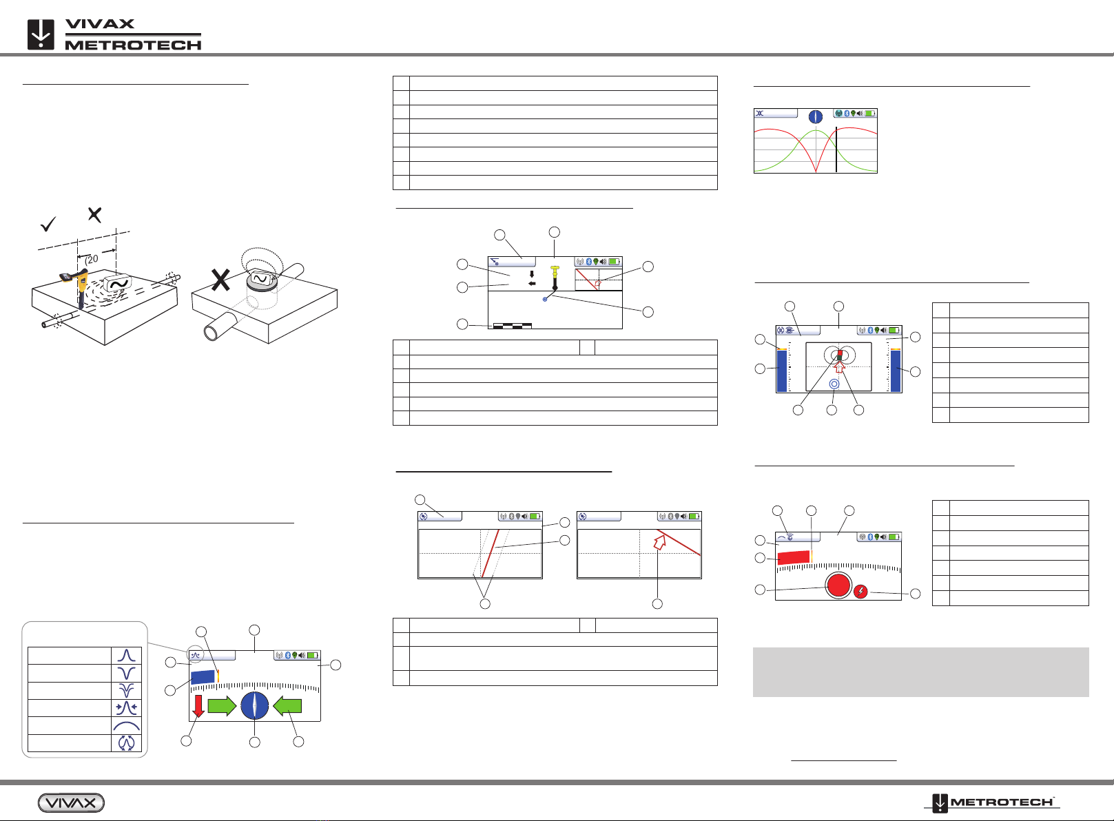
The target line is below the receiver when
both signal peaks are on the center line
and the signal is not distorted.
The center line does not indicate the target
line, but serves as an orientation for the two
signal peaks and the alignment to the cable!
If the signal path is distorted, or the two signal peaks are not on the
center line, there is interference in the electromagnetic field. To
determine the exact position of the cable now, please refer to the
user manual, section "Distorted fields".
Advantages: Automatic gain adjustment; Optimal analysis of signal distortion.
Sonde Location Mode (vLoc3-Pro user manual page 25)
Locating non-metallic pipes with a sonde.
3’9”
33dB 14.1mA 8.19kHz
67.2
25dB
8kHz
22
3 4 5
6
8 7
1
*
**
Observe the safety instructions in the manual regarding the handling of
the devices, measurement results and Li-ion batteries!
Read the exact settings, evaluations and safety instructions for
locating in the user manual!
Advantages: Simple marker location with immediate depth measurement at
the push of a button. For more details on the dual mode with parallel line and
marker location, please refer to the user manual.
Marker detection (vLoc3-ML user handbook page 36)
Pinpoint (EMS) Marker
Valid for vLoc3-ML or vLoc3 receiver with vLoc3-MLA attached.
19.1
12dB
1
2
34
7 6 5
Transverse Plot Screen (vLoc3-Pro user manual page 15)
Analyze the field shape at a particular location.
4 5
www.vivax-metrotech.com
6
Other manuals for vLoc3 Series
7
This manual suits for next models
3
Other Vivax Metrotech Receiver manuals

Vivax Metrotech
Vivax Metrotech vLocCam2 User manual

Vivax Metrotech
Vivax Metrotech vLoc3-Pro Instruction Manual

Vivax Metrotech
Vivax Metrotech vLoc-5000 Instruction Manual

Vivax Metrotech
Vivax Metrotech vLoc3-Pro Instruction Manual

Vivax Metrotech
Vivax Metrotech vLoc3 Series Instruction Manual

Vivax Metrotech
Vivax Metrotech vLoc3-DM Instruction Manual

Vivax Metrotech
Vivax Metrotech vLoc3 Series User manual

Vivax Metrotech
Vivax Metrotech vLoc3-Pro Installation guide

Vivax Metrotech
Vivax Metrotech vLoc3 Series User manual


