Vive Comfort TP-W150W User manual

INSTALLATION MANUAL
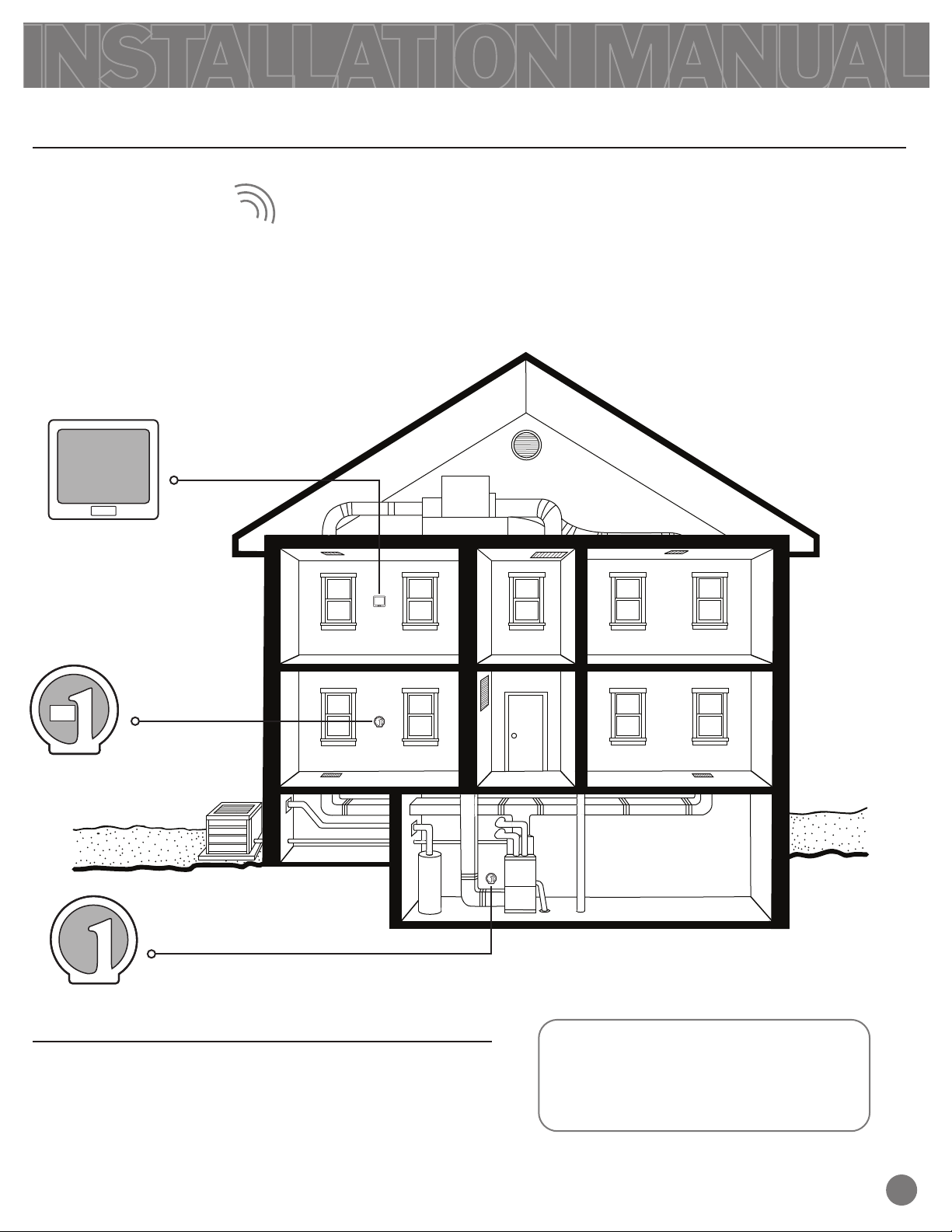
Applications GuideApplications Guide
Hardwire (Common Wire)
24V AC (18-30V)
Power Type
1
Table of Contents Page
Wireless Modules Quick Reference
Installation Tips
Subbase Installation
Mounting & Battery Installation
Specications
2
3
4
5
6
916 MHz916 MHz
RF Frequency
The wireless repeater extends the signal range
of many of our wireless products. When
the TP-W150W receives a coded wireless
signal, it repeats it to extend the wireless range
of the device.
Rev. 1340
A trained, experienced technician
must install this product.
Carefully read these instructions. You
could damage this product or cause a
hazardous condition if you fail to follow
these instructions.
Patents and Trademarks pending.
Copyright © 2013. All rights reserved.
Una versión en español de este
manual se puede descargar en la
página web de la compañía.
TP-W150W
COM F O R T
TM
VIVE Comfort
P.O. Box 3377
Springeld, MO 65804
Toll-Free: 1-800-776-1635 Web: www.vivecomfort.com
Hours of Operation: M-F 9AM - 6PM Eastern

When powered, the set Reference Number of
communicating devices appears on the LCD .
To determine the Reference Number needed
(1, 2, 3, or 4) for your devices; see chart below.
To enter Reference Number selection mode,
press the Module Button . The Reference
Number will start ashing. While Flashing, press
Module Button again to select Reference
Number needed. Once Selection is made, stop.
The number will quit ashing in 5 seconds, and
the Device Reference Number is set.
2
Getting to know the TP-W150W Module
Visit our website to learn more about our other wireless family of products.
1
2LCD
Indicator Light
1
3
2
Important:
WIRELESS MODULES QUICK REFERENCE
1.
2.
Connecting to Devices
Wireless modules must have 24VAC
power connected on R and C.
Wireless Tips
3Module Button
Transmit symbol
indicates repeating
signal.
Antenna symbol
indicates received
signal.
Reference number indicates
the current repeater mode.
1
2
3
Z955W, Z270W, Z260W
Z955W, S-955WH, Z251W,
ZDA250W, ROS-250W, RIS-251W
S-955WH
Ref. #
Communication Path
(Master Thermostat to:)
Select the reference number that corresponds to the devices.
4
TP-N-631W
Model Numbers
Involved
- Equipment Base Module
- Damper Module
- Zone Thermostat
- Outdoor Remote Sensor
- Discharge Air Sensor
- Equipment Base Module
- Equipment Base Module
1
2
3
Communication Note
When the TP-W150W receives a coded wireless
signal the “ ” Symbol will ash 3 times.
Immediately following, the coded wireless
signal is repeated as the “ ” Symbol and
Indicator Light ash 3 times.
3
INSTALLATION TIPS
Do not install the wireless module in locations:
• That are behind a chimney.
• Where temperature could exceed 120ºF.
• Where exposed to rain or snow.
• Where exposed to extreme hot or cold.
NOTE: The wireless modules are NOT weatherproof.
Wireless Module - Installation
Installation Tip
Wireless Range
Range between the TP-W150W module and the devices to be repeated is up to 100 feet with no
obstructions and up to 50 feet in standard residential construction. The TP-W150W module
should be installed between the wireless devices. To extend the range try placing the modules
closer together and/or further away from large metal objects.
TP-S-955WH
TP-W150W
BASE MODULE
Note:
The TP-W150W Reference Number
is set to 3 in this example.
3

SUBBASE INSTALLATION & WIRING
For vertical mount put one screw top
and one screw bottom.
For horizontal mount put one screw left
and one screw right.
Mounting the wireless module subbase
4
The TP-W150W must be hardwired (C and R terminals
connected to 24VAC power). Turn o power while wiring.
W150W Power Supply
Wiring Module to Power Supply
Horizontal mount
Horizontal mount
Vertical mount
UP
R
C
Vertical mount
Warning:
All components of the control
system and the thermostat
installation must conform to
Class II circuits per the NEC Code.
Caution: Electrical Hazard
Failure to disconnect the power
before beginning to install this
product can cause electrical shock
or equipment damage.
Wiring Note:

Do not install the wireless module in locations:
• That are behind a chimney.
• Where exposed to rain or snow.
• Where exposed to extreme hot or cold.
NOTE: The wireless modules are NOT weatherproof.
Installation Tip
5
MOUNT THE WIRELESS MODULES
Mount the Wireless Modules
Align the 4 tabs on the subbase with corresponding
slots on the back of the wireless modules. Then
push gently until the wireless repeater snaps in place.
Note:
The wireless modules can be wired
from the back or the bottom.
• Where temperature could exceed 120°F.

VIVE Comfort
P.O. Box 3377
Springeld, MO 65804
Power source
Operating ambient
Operating humidity
Frequency
Dimensions
18 to 30 VAC, NEC Class II, 50/60 Hz for hardwire (common wire)
+32ºF to +122ºF ( 0º to +50ºC )
90% non-condensing maximum
916 MHz
4.4”W x 4.4 ”H x .75”D
SPECIFICATIONS
Specications
6
Warranty Registration:
Your new wireless repeater has a 5 year limited warranty. You must register your warranty
within 60 days of installation. You can register your new product in 2 ways.
Go to our website, select warranty registration and ll out a short registration form.
- or -
Complete the form below and mail it to the address shown.
1
2
Complete form and mail to:
Thermostat Warranty Registration
Name: ____________________________
Address: ____________________________
____________________________
City: ____________________________
State: ____________________________
Zip: _____________________
Thermostat Model: _____________________
Date Installed: _____________________
Warranty Registration:
Table of contents


