INSTALLATION GUIDE FOR RA-2100 (MCPA)
RA-2100 (MCPA) QI Copyright - refer to title page Page 4
ENU Status : 1-0-0
0.3 INDEX TO FIGURES AND TABLES
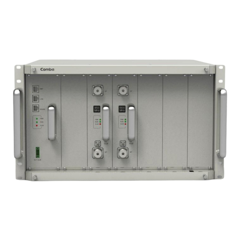
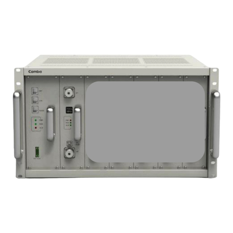
Figure 1: View of MOU............................................................................................................................... 14
Figure 2: Font, side and bottom views of the RRU enclosure ................................................................... 14
Figure 3: MOU system diagram ................................................................................................................. 15
Figure 4: RRU system diagram.................................................................................................................. 15
Figure 5: Application of one MOU with one RRU through Single Channel FOU with internal WDM ........ 16
Figure 6: Application of one MOU with two RRUs through Dual Channel FOU with internal WDM ......... 16
Figure 7: Application of one MOU with one RRU through Single Channel FOU with external WDM ....... 17
Figure 8: Application of one MOU with two RRUs through Dual Channel FOU with external WDM ........ 17
Figure 9: Application of one MOU with four RRUs through two Dual Channel FOUs with internal WDM 18
Figure 10: Application of one MOU with one RRU through Single Channel FOU..................................... 18
Figure 11: Application of one MOU with two RRUs through Dual Channel FOU ...................................... 19
Figure 12: Application of one MOU with one RRU through Single Channel FOU with WDM installed
externally.................................................................................................................................................... 19
Figure 13: Application of one MOU with two RRUs through Dual Channel FOU with WDM installed
externally.................................................................................................................................................... 20
Figure 14: Application of one MOU with four RRUs through two Dual Channel FOUs............................. 20
Figure 15: Application of one MOU with one RRU through Single Channel FOU with WDM installed
externally.................................................................................................................................................... 21
Figure 16: Application of one MOU with two RRUs through two Dual Channel FOUs ............................. 21
Figure 17: Front view of one MOU with one RRU through single channel FOUs with WDM and DIV...... 22
Figure 18: Front view of one MOU with four RRU through dual channel FOUs without WDM and DIV ... 22
Figure 19: Front view of one MOU with three RRU through one single channel FOU and one dual
channel FOU with WDM and without DIV.................................................................................................. 23
Figure 20: Front view of one MOU with four RRU through dual channel FOUs without WDM and DIV ... 23
Figure 21: Equipment internal layout of RRU without DIV.........................................................................24
Figure 22: Equipment internal layout of RRU with DIV.............................................................................. 24
Figure 23: Rack mounting of MOU ............................................................................................................ 30
Figure 24: Mounting rack dimension.......................................................................................................... 31
Figure 25: mounting rack secure details.................................................................................................... 31
Figure 26: RRU enclosure lifting lug attachment details............................................................................ 32
Figure 27: Wall mounting overview............................................................................................................ 32
Figure 28: Pole mounting overview............................................................................................................ 33
Figure 29: Attaching the RRU onto the mounting rack .............................................................................. 34
Figure 30: MOU Back Panel View ............................................................................................................. 41
Figure 31: Rear-shelf connectivitity of one MOU with one RRU through one single channel FOU .......... 41
Figure 32: Rear-shelf connectivity of one MOU with two RRU through one double channel FOU ........... 42
Figure 33: Rear-shelf connectivity of one MOU with three RRU through one double channel and one
single channel FOUs.................................................................................................................................. 42
Figure 34: Rear-Shelf connectivity of one MOU with four RRU through two double channel FOUs ........ 42
Figure 35: RA-2100 RRU with AC110V PSU ............................................................................................ 43
Figure 36: Pin allocation for “BTS_ALM” port ............................................................................................ 46
Figure 37: Pins allocation for “EXT_ALM” Port.......................................................................................... 46
Figure 38: Wireless modem ....................................................................................................................... 47
Figure 39: Diagram of wireline modem...................................................................................................... 48
Figure 40: Location of RRU LED indicators............................................................................................... 50
Figure 41: OMT v3.20 desktop .................................................................................................................. 51
Figure 42: “O” ring fitting details................................................................................................................. 59
Table 1: MOU shelf equipping rule ............................................................................................................ 23
Table 2: RA-2100 Regular KOP................................................................................................................. 26
Table 3: MOU KOP .................................................................................................................................... 26
Table 4: RRU KOP..................................................................................................................................... 26
Table 5: PSU SIU description .................................................................................................................... 35
Table 6: MCU SIU description ................................................................................................................... 36
Table 7: RFU SIU description .................................................................................................................... 37
Table 8: RFU-DIV SIU description ............................................................................................................. 38
