Vividia VO-HD51HM User manual

KS035200G4-Ver1.0
Camera Eyepiece
User’s Manual

Camera Eyepiece User’s Manual
KS035200G4-Ver1.0
Content
CHAPTER 1 NOTES AND SAFETY REQUIREMENTS------------------------- - 1 -
1.1 Cautions and Notes------------------------------------------------------------------- - 1 -
CHAPTER 2 SOFTWARE SYSTEM REQUIREMENTS ------------------------ - 2 -
2.1 System Requirements for HDMI Work Mode ------------------------------------ - 2 -
2.2 System Requirements under USB Work Mode ----------------------------------- - 2 -
CHAPTER 3 PACKING LIST ---------------------------------------------------------- - 3 -
CHAPTER 4 FUNCTION INTRODUCTION OF EACH PART ---------------- - 4 -
4.1 Name and Function for Each Part of the Camera Eyepiece Body ------------- - 4 -
4.2 Accessory Introduction -------------------------------------------------------------- - 6 -
4.3 Introduction of Optional Accessories ---------------------------------------------- - 6 -
CHAPTER 5 PRODUCTASSEMBLY GUIDE-------------------------------------- - 7 -
5.1 Camera Eyepiece Assembly--------------------------------------------------------- - 7 -
5.1.1 Camera Eyepiece and Other Microscope Assembly ------------------------ - 7 -
5.1.2 Camera Eyepiece Detachment ------------------------------------------------- - 9 -
CHAPTER 6 INSTRUCTIONS--------------------------------------------------------- 10 -
6.1 HDMI MODE ------------------------------------------------------------------------- - 10 -
6.1.1 Use of the back focal length eye height of the Camera Eyepiece --------- 10 -
6.1.2 Introduction of Various Functions --------------------------------------------- 11 -
1)Photography---------------------------------------------------------------------- 11 -
2)Record ---------------------------------------------------------------------------- 11 -
3)Playback -------------------------------------------------------------------------- 12 -
4)Freeze----------------------------------------------------------------------------- 12 -
5)Menu Setup ---------------------------------------------------------------------- 12 -
6)Exposure Setup ------------------------------------------------------------------ 13 -
7)White Balance Adjustment----------------------------------------------------- 14 -
6.2 USB Mode----------------------------------------------------------------------------- 15 -
6.2.1 Install Oasis Scientific Software----------------------------------------------- 15 -
6.2.2 Connect the Device-------------------------------------------------------------- 15 -
6.2.3 Open the Software--------------------------------------------------------------- 15 -
6.2.4 Read TF card --------------------------------------------------------------------- 15 -

Camera Eyepiece User’s Manual
KS035200G4-Ver1.0
- 1 -
Chapter 1 Notes and Safety Requirements
1.1CautionsandNotes
(1)To avoid danger or damage incurred to the lens, do not touch the lens or sensor
directly with your fingers.
(2)To avoid failure or electric shock hazard and so on, do not disassemble or
modify the internal structure of the device.
(3)Do not plug in or unplug the USB port when hands are wet.
(4)Do not use alcohol and other organic solvents to clean.
(5)If the lens or sensor is dirty or damp, you should better use dry and non-linen
fabric or professional lens tissue to wipe them. To avoid scratches on the
surface, do not touch the lens with your fingers. Wipe the lens or sensor lightly.
(6)The products are not specifically designed for an outdoor use. Do not expose it
to outdoor environment without any protection. Excessive temperature and
humidity will damage the lens. Please avoid using the product under the
following environment: high temperature or high humidity environment, places
with direct sunlight, dirt or vibration and places near heat source.
(7)Please use and store in the following environment:
Operating temperature :0℃~ 40℃
Storage temperature:-20℃~ 60℃
Operating Humidity:30~80%RH
Storage Humidity:10~60%RH
(8)If any foreign matter, water or liquid enter into the device by accident,
disconnect the USB cable immediately. Please send it to the maintenance center
and do not use the hair dryer to dry it by yourself.
(9)To prevent microscope from being tripped over or dropped, please put away the
device's USB cables in use or standby.
(10)To avoid electric shock by accident, please power off microscope before you
move your computer or laptop.
(11)The cleanliness of the device lens will directly affect clarity degree of contents
from the computer screen during preview. Problems like various circles or spots
on the screen may mostly be incurred by dirt on the lens. When cleaning, please
use professional lens tissue or other professional detergent to clear the dirt on
the lens.

Camera Eyepiece User’s Manual
KS035200G4-Ver1.0
- 2 -
Chapter 2 Software System Requirements
2.1SystemRequirementsforHDMIWorkMode
●Displayer: for best observation effects, 1080P or higher resolution with
HDMIA interface, screen of 19 or higher inches with size proportion 16:9
should be used.
2.2SystemRequirementsunderUSBWorkMode
●Windows XP SP3、Windows 7(32 or 64 bits)、Windows 8(32 or 64 bits)、
Windows 8.1(32 or 64 bits)、Windows10(32 or 64 bits)。
●Dual core 1.6 GHz or higher CPU
●USB 2.0 high-speed interface or USB2.0 compatible interface
●DVD-ROM driver (only needed when installing software)
●2G or more memory
●At least 4 GB available hard-disk space
Camera Eyepiece User’s Manual
KS035200G4-Ver1.0
- 3 -
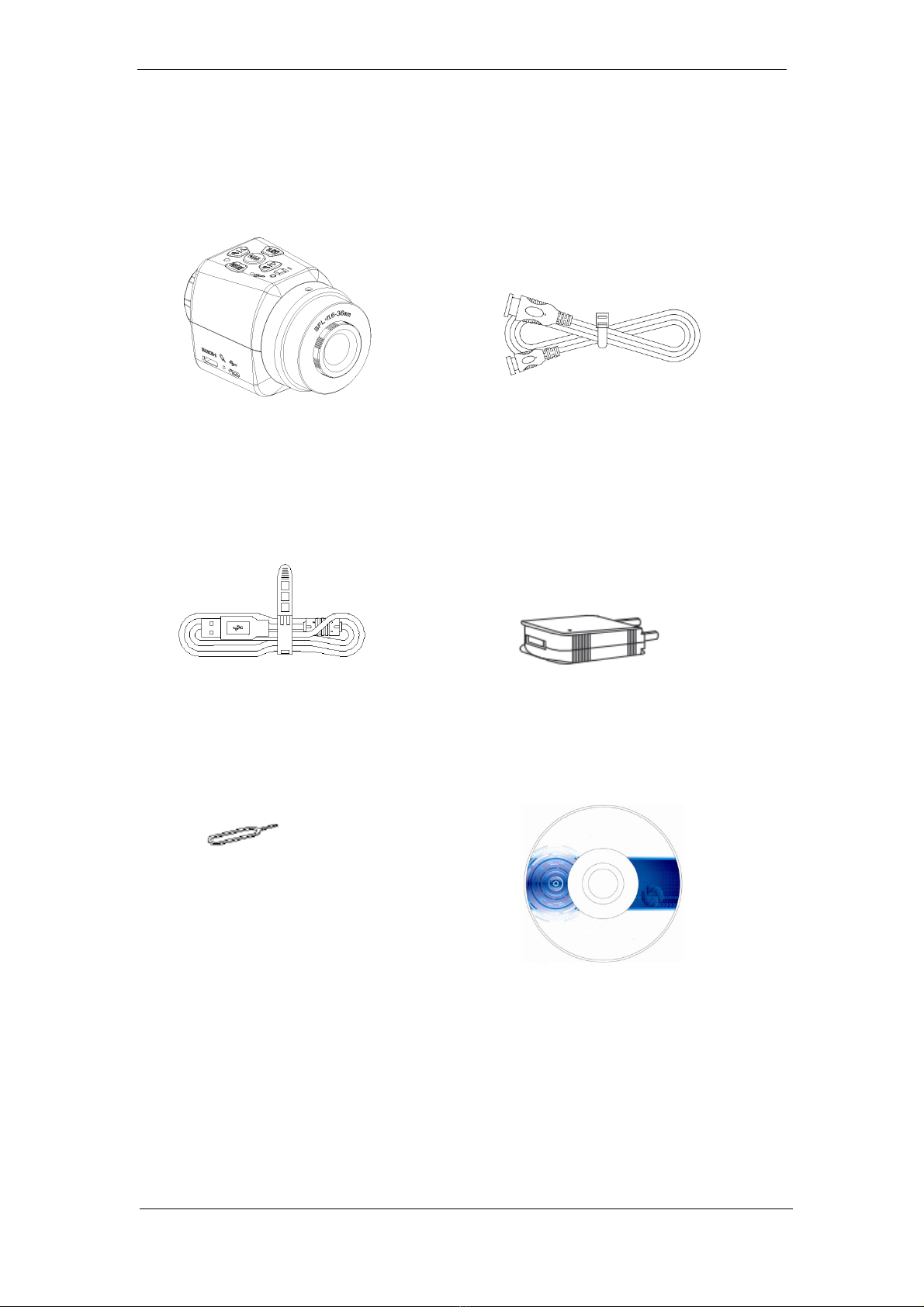
Chapter 3 Packing List
1、Mainbody 2、HDMI Line
3、USBLine 4、Adapter
5、Resetpin 6、Installation disk

Camera Eyepiece User’s Manual
KS035200G4-Ver1.0
- 4 -
Chapter 4 Function Introduction of Each Part
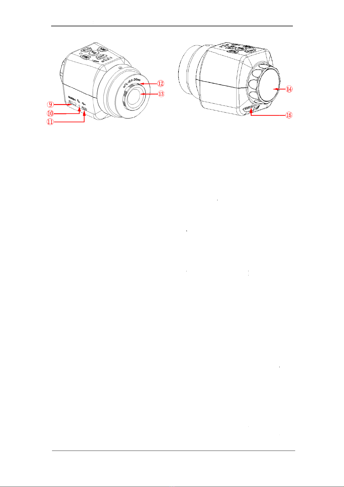
4.1 Name and Function for Each Part of the Camera Eyepiece
Body
①Work Indicator
:(1)Red and green light on when the device is power
on but not been started up.
(2)Green light is on when the machine is started up.
(3)Green light flashes when recording is processed.
(4)Red and green light flashes when the card
(including no card insertion, maximum card
storage capacity and card recognition error) is
wrong.
②Menu/WB button:Menu/automatic white balancing function.
③Microphone:Record sound when video is recording.
④Toggle switch for
machine on/off
:Machine on, machine off.
⑤Zoom in/upward button:Zoom in/ upward/ freeze/ video fast backward.
⑥Photograph/Record
button
:Record/ photograph/ backward play.
⑦Mode/Yes/AE button
:Mode/ yes/ automatic exposure function. Mode
includes photograph, backward play and record.
⑧Zoom out/downward
button
:Zoom out/ downward/ fast forward.
Camer
⑨
M
⑩
R
⑪
M
⑫
P
⑬
D
⑭
E
⑮
T
a Eyepiece User’s
M
M
icro USB
R
eset pole
M
ini HDM
I
P
ort C thre
a
D
ust cove
r
E
ye-height
a
T
F card slo
t
M
anual
port
I
port
ad
a
djustment
t
:
:
:
:
:
ring :
:
- 5 -
The c
o
Re-st
a
The
c
port.
Port
C
port
C
Conn
e
port
C
micro
s
speci
f
Dust
c
chips.
It is
fo
adjus
t
BFL=
TF ca
r
64G.
T
recor
d
store
d
recor
d
Befor
e
card
remin
d
reach
e
recor
d
savin
g
TF ca
r
conne
acces
s
simul
t
“mod
e
acces
s
o
nnection
p
a
rt the mac
h
c
onnection
C
thread c
a
C
, CS po
r
e
cted with
C
thread ca
s
cope w
i
f
ications
:1
c
over is fo
r
fo
r the adju
s
ment rang
e
11.6-36m
m
r
d slot sup
p
T
F card do
d
ing files
o
d
, TF card
d
ing or pho
t
e
photogra
p
isn’t been
d
users to
i
e
s its ma
x
d
ing will a
u
g
, and also
r
d at the sa
m
cted to c
o
s
the fi
l
t
aneously
e
”, and aga
i
s
ing the TF
K
p
ort of the
U
h
ine.
port of th
e
a
n be direc
t
r
t microsc
o
eyepiece
n realize t
h
i
th differ
e
“X1/32”)
r
covering
d
s
tment of t
h
e
of the b
a
m
.
p
orts the m
a
esn’t supp
o
o
r photos
a
needs to
b
t
ography.
p
hy and re
detected,
i
nsert TF c
a
x
imum sto
r
u
tomaticall
y
reminds u
s
m
e time.
W
om
puter b
y
l
e of th
e
press b
u
i
n press the
card.
K
S035200G4-
V
U
SB line M
i
e
HDMI li
n
t
ly connec
t
o
pe and te
l
(accessori
e
h
e connecti
e
nt ports
d
ust and pr
h
e eye hei
g
a
ck focal l
e
a
ximum ca
p
o
rt hot swa
p
a
re require
d
b
e inserte
d
cording, i
f
the mach
i
a
rd. If the
T
r
age capa
c
y
stop and
s
ers to repl
a
W
hen the m
a
y
USB, us
e
TF c
a
u
ttons “m
e
two butto
n
V
er1.0
i
cro.
n
e Mini
t
ed with
l
escope.
e
s), the
on with
.
(
thread
otecting
g
ht. The
e
ngth is
p
acity of
p
. If the
d
to be
d
before
the TF
i
ne will
T
F card
c
ity, the
process
a
ce new
a
chine is
ers can
a
rd by
e
nu”and
n
s to exit
Camera Eyepiece User’s Manual
KS035200G4-Ver1.0
- 6 -
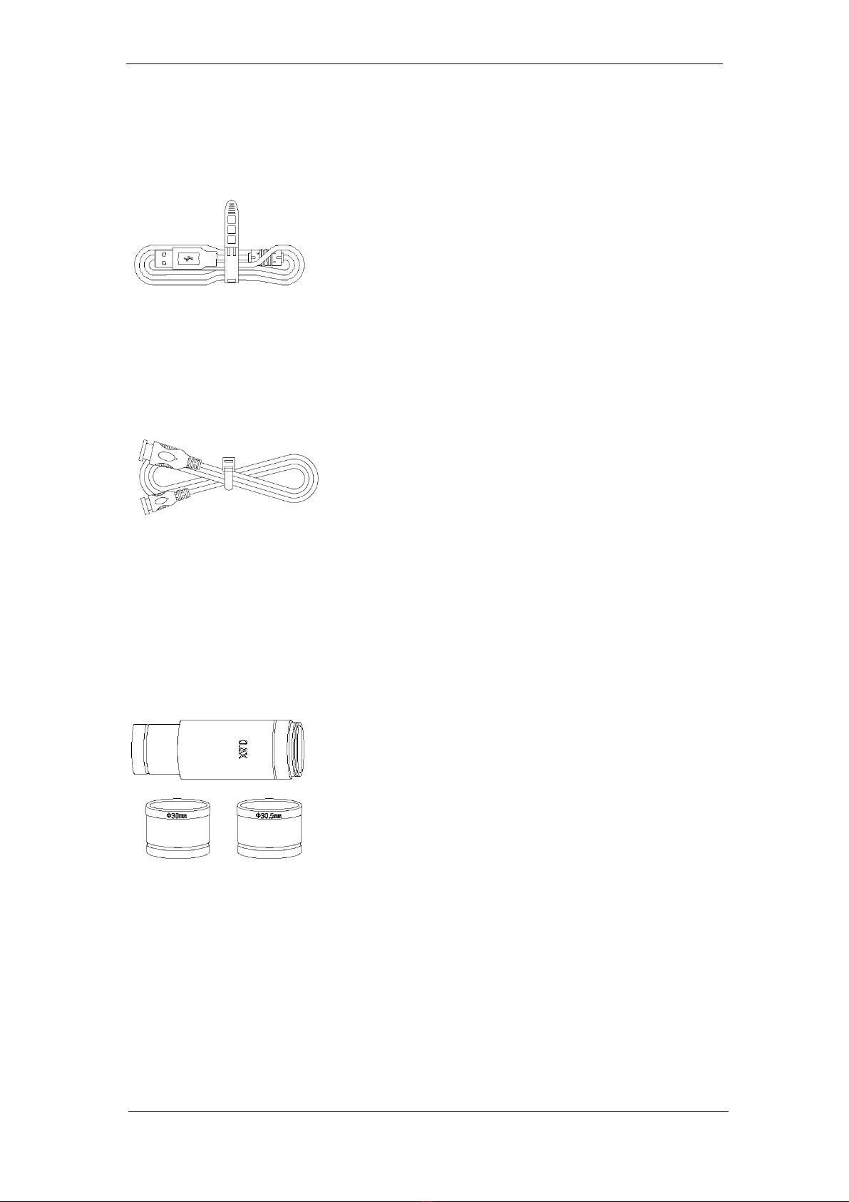
4.2 Accessory Introduction
USB Line
:
Two functions:
1、Under the state of HDMI: USB
can be used as the power line.
2、When connected with PC port:
USB can be used as the
connection line between Camera
Eyepiece and computer data.
HDMI line
:
Data connection line between
machine body and displayer.
4.3 Introduction of Optional Accessories
Adaption ring
and eyepiece
(Optional
Accessories)
:
Through adaption ring and
eyepiece, Camera Eyepiece can
be adapted to microscope with
different calibers. The Camera
Eyepiece itself can be adapted to
port C or CS. Under different
magnification ratio, the caliber of
eyepiece 0.5X is 23.2mm,
adaption ring 23.2/30mm and
23.2/30.5mm. According to
different assembly ways, the
adaption ring and eyepiece can
realize the connection between
the device and eyepiece with
different port size.

Camera Eyepiece User’s Manual
KS035200G4-Ver1.0
- 7 -
Chapter 5 Product Assembly Guide
5.1 Camera Eyepiece Assembly
5.1.1 Camera Eyepiece and Other Microscope Assembly
1. Connect to Microscope with standard port C
(1) Twist off the dust cover plastic cap under the Camera Eyepiece.
(See picture 1)
(2) Twist the Camera Eyepiece onto other microscope (standard port C)
(See picture 2)
(3)Connect the Micro USB port of USB line with Camera Eyepiece. Under HDMI
mode, connect the other port to power adapter. Under USB mode, connect the
other port with USB output port of the computer.
(4)Connect the Mini HDMI port of the HDMI to Camera Eyepiece, and the other
port to displayer with HDMI port.(This step can be skipped under USB work
mode.)
Picture 1
Picture 2
Camera Eyepiece User’s Manual
KS035200G4-Ver1.0
- 8 -
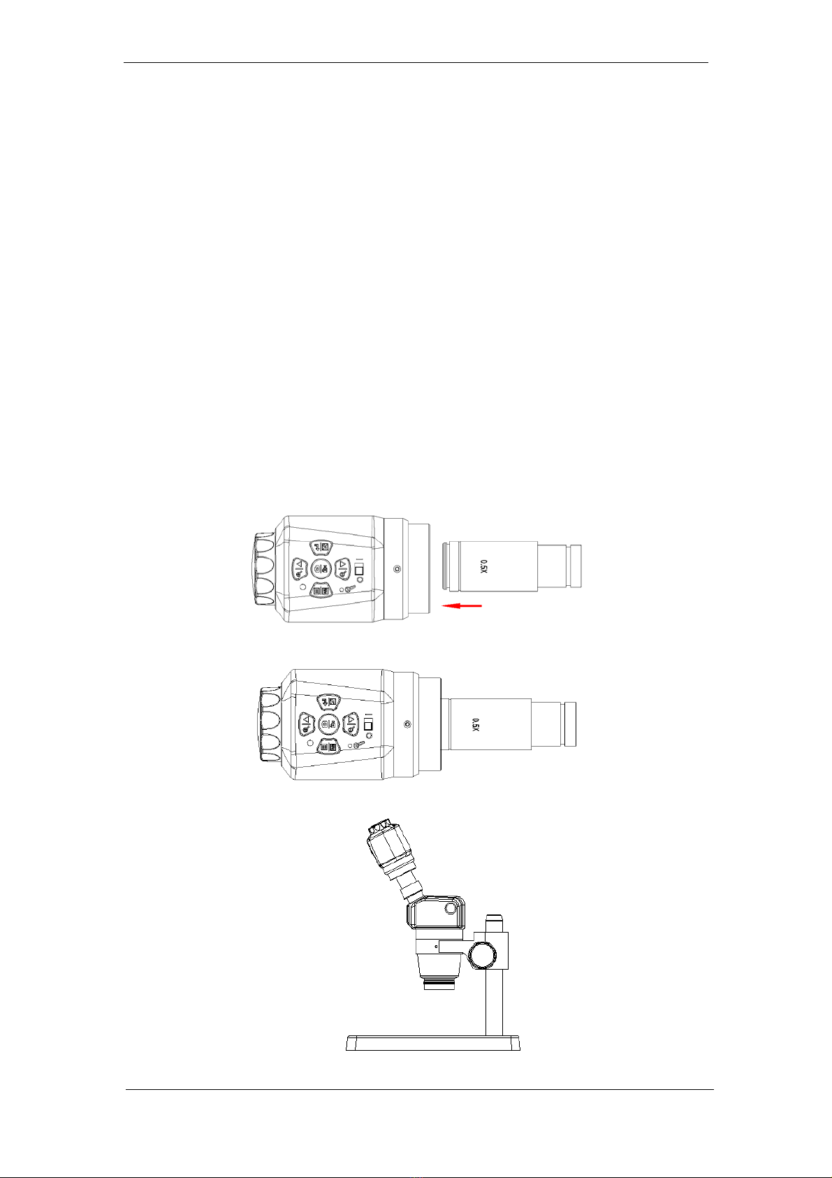
2. Connect the stereoscopic microscope
(1) Twist off the dust cover cap of the Camera Eyepiece.
(2) Connect the Camera Eyepiece with appending eyepiece (see picture 3 and 4).
(3) Embed the minifier (or hollow cylinder) into adapter ring 23.2/30mm
(or 23.2/30.5mm ).
(4) Embed the adapter ring with Camera Eyepiece to stereoscopic microscope
(See picture 5).
(5) Connect the Micro USB port of USB line with Camera Eyepiece. Under HDMI
mode, connect the other port to power adapter. Under USB mode, connect the
other port with USB output port of the computer.
(6) Connect the Mini HDMI port of the HDMI to Camera Eyepiece, and the other
port to displayer with HDMI port.(This step can be skipped under USB work
mode.)
Picture 3
Picture 4
Picture 5

Camera Eyepiece User’s Manual
KS035200G4-Ver1.0
- 9 -
5.1.2 Camera Eyepiece Detachment
1. Detach with eyepiece of standard C port
(1)The machine is under shutdown condition.
(2)Pull out USB cable and HDMI cable.
(3)Twist off the Camera Eyepiece from the microscope.
(4)Screw on the dust cover plastic cap.
(5)Place the Camera Eyepiece to avoid being dropped.
2. Detach with Stereoscopic Microscope
(1)The machine is under shutdown condition.
(2)Pull out USB cable and HDMI cable.
(3)Take out the product with the adapter ring from the stereoscopic microscope.
(4)Detach the adapter ring and eyepiece from the product.
(5)Screw on the dust cover plastic cap.
(6)Place the Camera Eyepiece to avoid being dropped.

Camera Eyepiece User’s Manual
KS035200G4-Ver1.0
- 10 -
Chapter 6 Instructions
Use under different modes:
1. HDMI Mode
2. USB Mode
Note: when connection with computer and HDMI is simultaneously detected, USB
port output of the PC will be first processed.
6.1 HDMI Mode
6.1.1 Use of the back focal length eye height of the Camera Eyepiece
1. Connect the relevant accessories such as Camera Eyepiece, microscope and
displayer, etc. (For detailed operation, please refer to Chapter 5)
2. Switch the toggle key to status of power on.
3. Rotate the eye height adapter ring clockwise or anti-clockwise to adjust the eye
height until the image is clearly displayed.
(1) Clockwise: BFL gets smaller.
(2)Anti-clockwise: BFL gets larger.
Note: For the magnification ratio and optical parameter of each eyepiece are
different, chances are that the image might not been adjusted clearly through
eye height adapter. In that case, coordinating adjustment operation distance
can be tried to achieve clearer image effects.
Camera Eyepiece User’s Manual
KS035200G4-Ver1.0
- 11 -
6.1.2 Introduction of Various Functions
a) 5 buttons are set on the machine body.
b) Short press refers to press time 0.2s~1s. Long press refers to press time more than
2s or above. (Without special reference, press below all means short press).
c) For 10 seconds without operation, the system will automatically hide the icon on
the screen desk for users to watch the video more conveniently. Users can press
arbitrary button to awake the desk icon.
d) The maximum magnification ratio of the zoom in function button: x4. Zoom out
function button can only be available when being zoomed in first.
e) 2304x1536, the highest resolution pixel of photography is 2304x1536.
f) Record: when the HDMI displays, the highest resolution pixel of recording is
1280x720. For recording without HDMI display, the highest resolution pixel is
1920x1080.
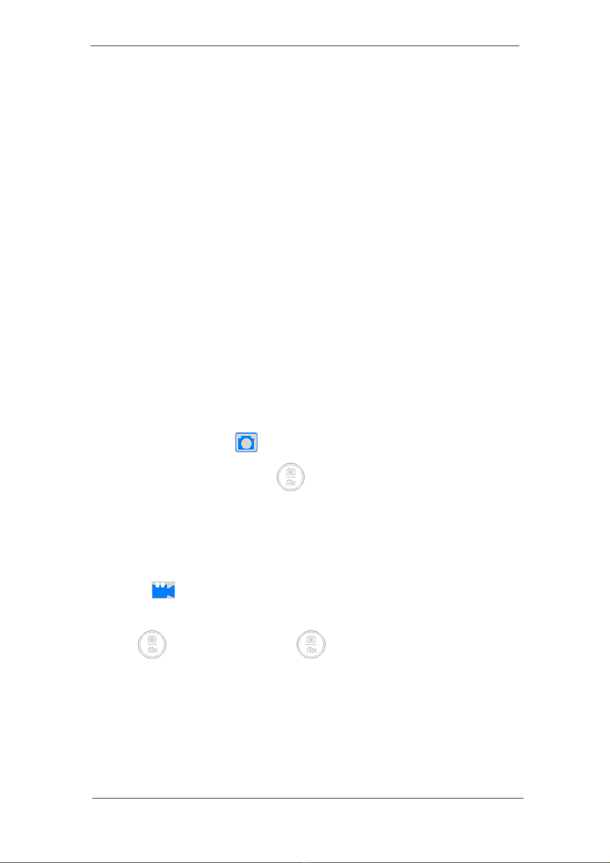
1)Photography
The top right corner icon “ ” displays for photography mode. Please ensure the
TF card insertion, press button“ ”for picture shooting. Pictures will be
automatically saved into the Photo file under TF card file Microscope.
2)Record
The icon “ ” on the top right corner of the screen displays for recording mode to
record sound and video files. Please ensure the TF card insertion, press
button“ ”for recording and press“ ”again to exit recording. Records will
be automatically saved into the Video file under TF card file Microscope.

Camera Eyepiece User’s Manual
KS035200G4-Ver1.0
- 12 -
3)Playback
Flip over for observation by pressing button“ ”or “ ”. Pressing
button “ ” can enter the file attributes interface, which includes three
operation functions such as delete, protect and slide show.
The icon “ ” on the top right corner means the picture is an photo.
The icon “ ” on the top right corner means the picture is a video. Press
“ ” to play/pause recording. Press “ ” or “ ” can fast
forward or fast backward during palying.
4)Freeze
Under photography or recording mode, long press “ ” to freeze the
picture and press “ ” to unfreeze it. When the picture is frozen, press
“ ” to save the frozen screen to picture.
5)Menu Setup
Pressing “ ” to enter the menu bar interface. Through button“ ” and
“ ” to move the cursor up and down for selecting the required function.
Press “ ” to enter into setup. After setup, press button “ ” to exit menu
bar.
Camera Eyepiece User’s Manual
KS035200G4-Ver1.0
- 13 -
Note: common functions are set up on the menu bar, namely exposure
compensation, white balancing, resolution, continuous capture, image quality,
sharpness, shooting ways, color, ISO, anti hand shake, quick preview, button
press sound and language.
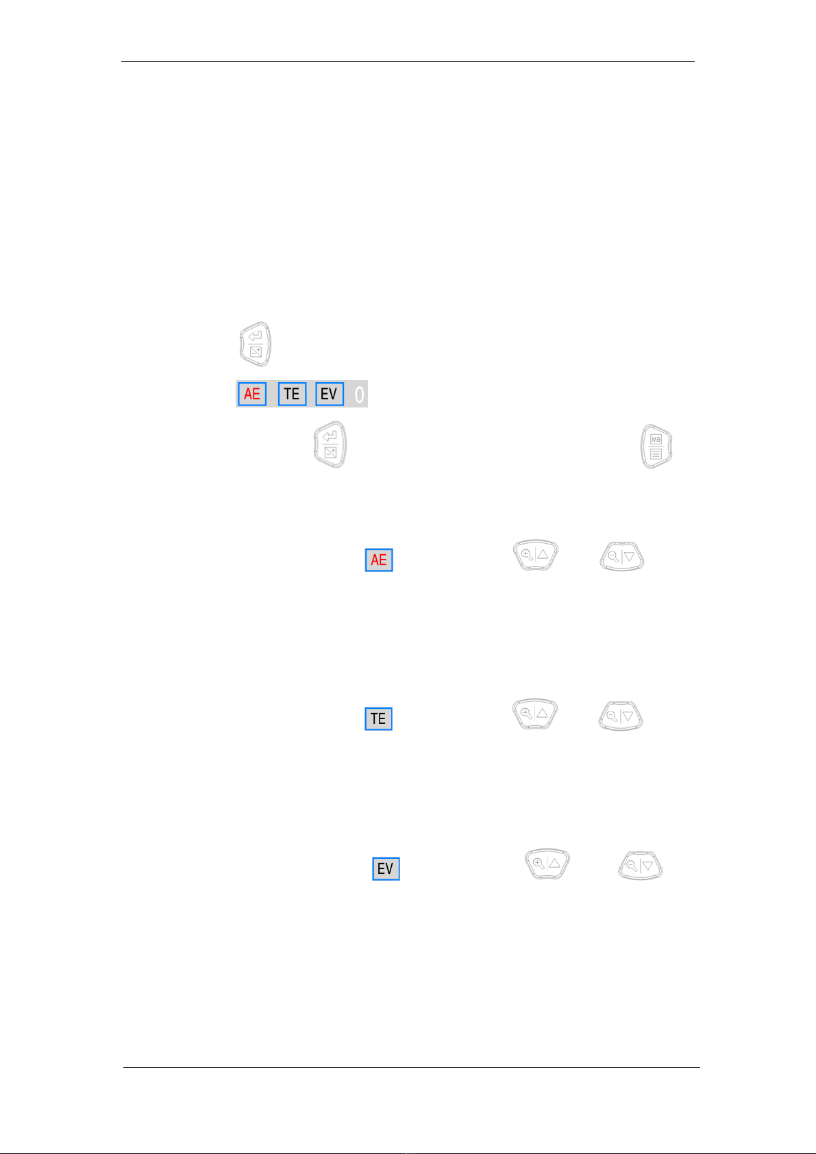
6)Exposure Setup
Long press “ ” to enter the exposure setup interface. The icon displayed on
the screen is . When the icon flashes, the moving cursor is in
current position. Press “ ” to choose option from right to left. Press “ ”
to exit the exposure setup interface.
(1) With the cursor pointed to , through button “ ” or “ ” to
start up or close the real-time automatic exposure function. Red icon AE
stands for starting real-time automatic exposure and black AE for closing
real-time automatic exposure.
(2) With the cursor pointed to , through button “ ” or “ ” to
process single automatic exposure. Red icon TE stands for ongoing real-time
automatic exposure and black TE for none automatic exposure or completed
automatic exposure.
(3)With the cursor pointed to , through button“ ” or “ ” to
change the current value. The valuable adjustment range is -6~+6 with default
value 0.

Camera Eyepiece User’s Manual
KS035200G4-Ver1.0
- 14 -
7)White BalanceAdjustment
Long press “ ”to enter AWB mode interface. The screen displays icon
. When the icon flashes, the cursor is in
current position. Press “ ” to choose option from right to left. Press “ ”
to exit AWB mode.
(1) With the cursor pointed to , through button“ ” or “ ” to
start up or close the real-time white balance. Red icon AWB stands for
starting real-time white balance and black AWB for closing real-time white
balance.
(2) With the cursor pointed to , through button“ ” or “ ”to
process TWB. Red icon TWB stands for processing single white balance and
black AWB for none single white balance or completed single white balance.
Note: since the time of processing automatic white balance is very short, the
icon TWB will not display red sign.
(3) With the cursor pointed to , through button“ ” or “ ” to
change current value. The effective adjustment range is 0~255 with default
value 128.
(4)With the cursor pointed to , through button“ ” or “ ” to
change current value. The effective adjustment range is 0~255 with default
value 128.
(5)With the cursor pointed to , through button“ ”or “ ” to change
current value. The effective adjustment range is 0~255 with default value 128.

Camera Eyepiece User’s Manual
KS035200G4-Ver1.0
- 15 -
6.2 USB Mode
6.2.1 Install Oasis Scientific Software
Put the accessory disk into the DVD of the computer, click the file Oasis Scientific
Install and complete the installation of the application software according to the
software prompts. For detailed installation methods, please refer to User Manual of
Oasis Scientific English.
6.2.2 Connect the Device
(1) Connect the Camera Eyepiece to the microscope or telescope.
(2) Connect the USB port of the Camera Eyepiece to the USB port of the computer.
(3) For detailed operation methods, please refer to Chapter 5.
6.2.3 Open the Software
(1) Place the eyepiece and focus the camera on the observed object.
(2) Pull the toggle keys on.
(3) Execute the software Oasis Scientific in computer. Through adjusting the eye
height or operation distance to observe the object.
6.2.4 Read TF card
After connected the Camera Eyepiece to the USB port of the PC, press “ ” to
switch the USB mode to TF card mode. Meanwhile a disk icon will be created on the
computer and the file in TF card of the Camera Eyepiece can be read through
computer.
Table of contents
Other Vividia Camera Accessories manuals


