Installation and Operational Guide
Surface Mounting Instructions
1. Place the unit against the mounting surface.
2. Mark the areas where the mounting holes are to be drilled. Confirm that no
vehicle parts could be damaged by the drilling process.
3. Drill two mounting holes and a 0.4”dia, using a bit that is sized for a #6 sheet
metal screw.
Wire passage hole(s) must also be drilled.
4. Route the wires through the hole(s) in the gasket and through the wire passage
hole(s) in the mounting surface. Secure the light head to the mounting surface.
sage hole if needed.
3. Secure the light head to the bracket with the supplied hardware.
MOUNTING
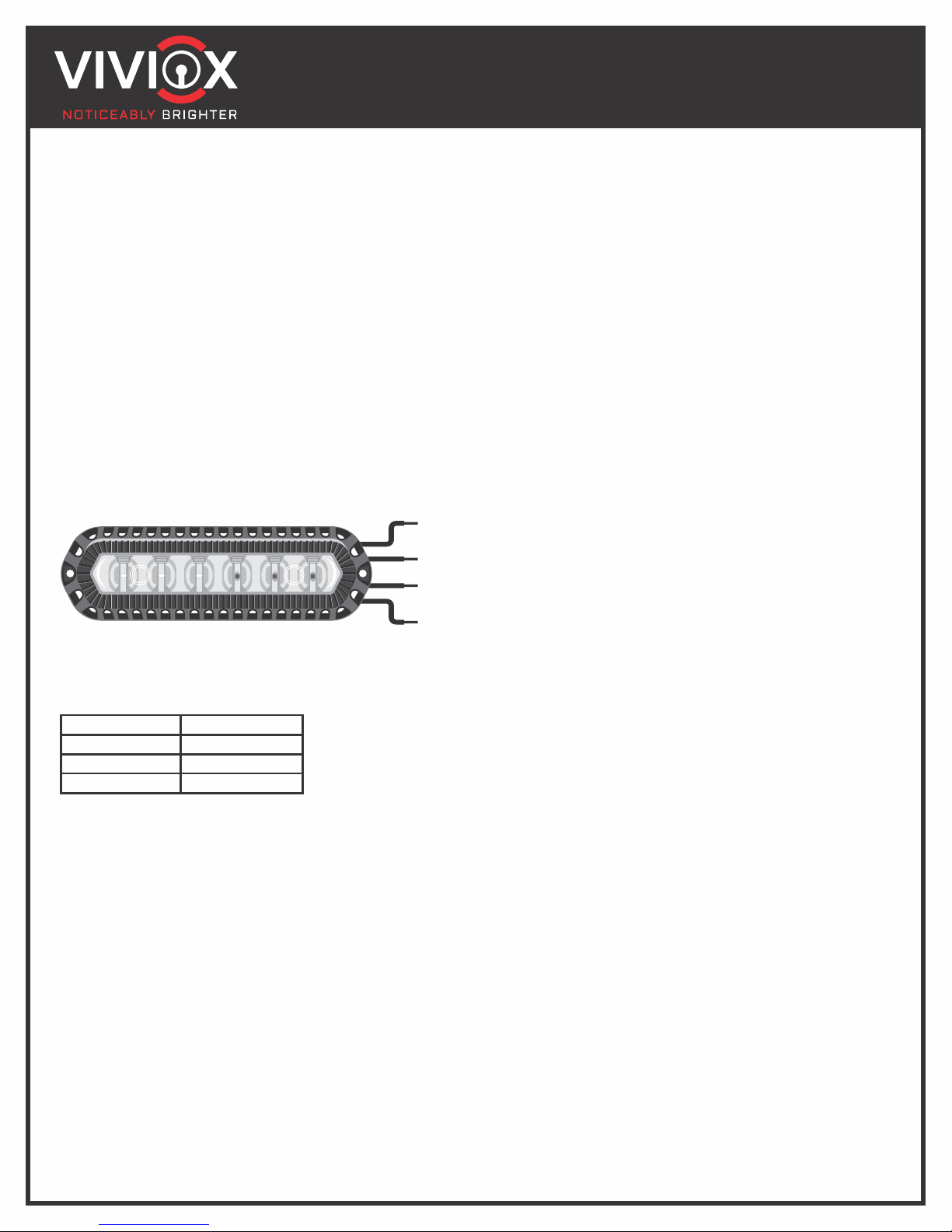
OPERATION (See Diagram Above)
1. Changing Patterns: Apply power to the white wire for
Less then a second
1-3 Seconds
3-5 Seconds
5+ Seconds
Next Pattern
Previous Pattern
Factory Default
Turn off and Reset
SPECIFICATIONS
WITH FLANGE
Dimensions: 5.5”L 1.125” H 1.125” D
Syncing Instructions: Configure all light heads to the same pattern and connect
the white wires from each light head together. Apply power to every other green wire
to alternate multiple light heads.
Input Voltage: 10-30VDC Input Current: 1.4A(MAX)
BLACK
GND-Ground
WHITE
Sync
RED
Positive
GREEN
Alternating
EE
EE
Please read the manual below for important information on your Viviox
product that could prevent damage or serious injury. Failure to follow our
instructions and other safety precautions could result in serious injury to
you or your passengers, and/or product and vehicle damage.
Important: The installation technician and operator must read this manual
before starting installation or operation of your new product. They must
have a thorough understanding of automotive systems, electronics and
procedures.
WARNING: Please understand that the user and installer assume
ultimate, complete and full responsibility in determining proper mounting
location and positioning. When installing, consider a location based on its
ability to provide total safety to all passengers.
WARNING: DO NOT USE CIRCUIT BREAKERS WITH THIS
PRODUCT! All customer-supplied wires that connect with the
positive (+) end of the battery must be able to support 125% or more of the
maximum operating current. They MUST be fused with the battery to
handle the current.
ŸBefore drilling and installation, check both sides of your mounting
service.
ŸGrommets should be installed into all wire passage holes.
ŸPlease read your vehicle's owner's manual; it contains important
information about the airbag deployment area. This product should
NOT, under any circumstances, be installed in the deployment area of
the vehicle's airbag. Do NOT route any wires in this area. Having
equipment mounted or located in this area is a serious risk; it could
reduce or damage the airbag's effectiveness, or even become a
projectile that could result in serious injury or death.
ŸThis device may feature powerful, bright, high-intensity LED lights. DO
NOT look at the lights directly, as momentary blindness and/or
permanent eye damage can occur.
ŸDO NOT try to activate or control this product during a hazardous or
dangerous driving situation.
ŸIf your device is controlled or activated by a remote, please double
check that the control is in a place that will allow for both the control
itself, as well as the vehicle, to be used safely in any driving condition
and/or situation.
Model E600-S
Light Heads
T. 844.3.VIVIOX
W. www.VIVIOX.com
E. support@VIVIOX.com


