Vivitek RP56HD21-A User manual


Contents
Introducing Your Micro Chip Display Projection TV..........1
Features....................................................................................................2
Important Safeguards................................................................................3
Package Contents.....................................................................................5
Accessories ..............................................................................................7
Turning on the Main Power........................................................................8
Front Controls ...........................................................................................9
Back Connections...................................................................................11
Side Connections....................................................................................12
Connecting Components........................................................................13
Understanding Video Connections ..........................................................14
Connecting your DVD Player...................................................................15
Using Component Video..................................................................15
Using S-Video .................................................................................16
Using DVI Video..............................................................................17
Using Composite Video...................................................................18
Connecting your HDTV Set-Top Box.......................................................19
Using Component Video..................................................................19
Using DVI Video..............................................................................20
Using RGB Video............................................................................21
Connecting your VCR or Video Camera..................................................22
Using S-Video .................................................................................22
Using Composite Video...................................................................23
Using Coaxial (RF)..........................................................................24
Connecting off-air TV or Cable TV ...........................................................25
Connecting ExternalAmplified Speakers .................................................26
Connecting an External Receiver orAmplifier ..........................................27
Connecting a Computer..........................................................................28
Using DVI Video..............................................................................28
Using RGB Video............................................................................29
i

Adjusting Your Micro Chip Display Projection TV Settings............30
Using the OSD........................................................................................31
OSD Menu and Options..........................................................................32
Maintenance and Troubleshooting.......................................................38
Cleaning and Maintenance......................................................................39

Introducing Your
Micro Chip Display Projection TV
This chapter provides basic information about Your Micro
Chip Display Projection TV.
Read this chapter to learn about :
Features
Warnings and Safeguards
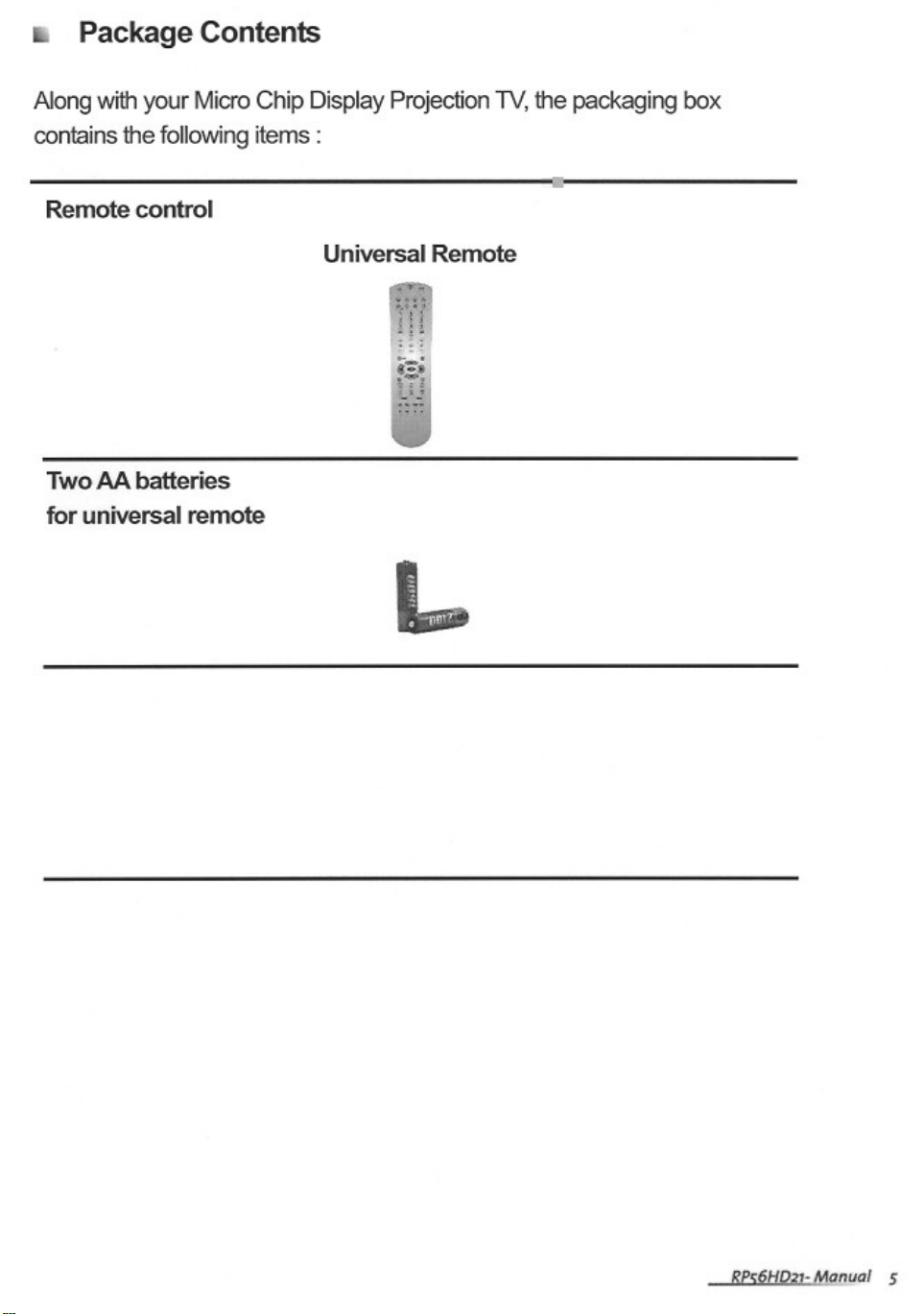
Package Contents
Controls and Connections

Features
Abright, flicker-free image
Automatic detection and conversion of film content for correct displayWith
minimal motion artifacts (noise)
Accurate color processing
Two high-definition component video input sources that automatically
synchronize the display to match the incoming source
Picture-in-picture (PIP) modes that let you watch multiple programs
simultaneously
HDTV signal compatibility using an external HDTV decoder with DVI, RGB
or component video outputs
HDCP support for video protection
Digital zoom mode to get rid of “black bars” around the displayimage
Abuilt-in BBE®sound processor that maximizes the sound quality
Abuilt-in SRS®sound processor that simulates “surround” effects using only
two speakers
Selectable fixed/variable audio outputs
Built-in internal amplifier and speakers
Abuilt-in Digital Visual Interface (DVI) to eliminate the need for
digital-to-analog conversion
1024 x 768 XGAsupport for computer input
480i, 480p, 720p and 1080i support for HDTV signals

Important Safeguards
Warning Risk of electric shock – Do not open this RPTV
To reduce the risk of electric shock, do not remove the back cover.
There are no user-serviceable parts inside. Removing the back
covervoidsthewarranty.Have your Micro Chip Display
Projection TV repaired by qualified service personnel only.
Warnings and precautions
Do not place your hands, face, or objects close to the ventilation openings of
your Micro Chip Display ProjectionTV.
Disconnect all cables before moving your Micro Chip Display ProjectionTV.
Moving your Micro Chip Display ProjectionTV with its cables attached may
damage the cables and cause fire or electric shock danger.
Do not expose your Micro Chip DisplayProjection TV to rain or moisture.
Keep your Micro Chip Display ProjectionTV away from excessive dust, high
temperatures, moisture or direct sunlight.
Use your Micro Chip Display ProjectionTV in a well-ventilated area and do
not cover the ventilation openings.
Do not modify your Micro Chip DisplayProjection TV or use an unshielded
power cord or video input source cable, or you may experience excessive
interference.
Disconnect your Micro Chip Display ProjectionTV and unplug the power
cord when not used for a long period of time.
If the picture displayed is in any way abnormal, turn off your Micro Chip
Display ProjectionTV, then disconnect it from the electrical outlet. Make sure
that your video input source cable is connected correctly, then reconnect
your Micro Chip Display ProjectionTV to the electrical outlet.
Disconnect your Micro Chip Display Projection TV from the electrical outlet
before cleaning or performing maintenance. Do not use liquid or aerosol
cleaners. Use only a slightly damp cloth for cleaning.
Do not place your Micro Chip Display ProjectionTV on an unstable cart,
stand, or table.Your Micro Chip Display Projection TV may fall, causing
serious damage.

Do not place your Micro Chip DisplayProjection TV on a bed, sofa, rug, or
other similar surfaces.
Never place your Micro Chip Display Projection TV near or over a radiator or
heat source.
Do not install your Micro Chip DisplayProjection TV in an enclosed area
unless correct ventilation is provided.
Your Micro Chip DisplayProjection TV should be operated from the type of
power source indicated on the label. If the type of available power is
unknown, consult your electrician or local power company.
Your Micro Chip DisplayProjection TV is equipped with a 3-pin grounded
plug. The plug will only fit into a grounded power outlet. This is a safety
feature. If you cannot plug the power cord into the outlet, contact your
electrician. Do not alter the plug becausf4 Te01ug bel15(any)85(. )]TJ/C2_0 1 180477 T66 Tc 0 Tw -2.67999 -1.5533 Td<0084000afety
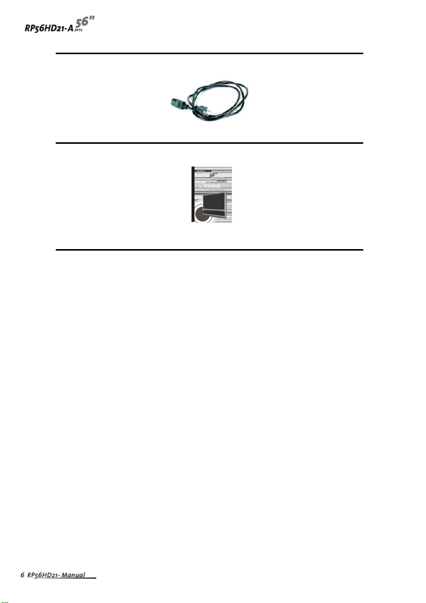
Power cord
User guide

Accessories
You can purchase these optional accessories for your Micro Chip Display
Projection TV :
Filters
Lamps
Contact for these and other accessories.

Turning on the Main Power
To turn on the power :
1Connect the power cord to the power cord connector on the back ofYour Micro
Chip Display ProjectionTV, then plug the other end of the power cord into a
correctly grounded electrical outlet or surge protector.
2Press the POWER button on the front of your Micro Chip Display ProjectionTV.
The Status LED on the front turns blue.
Warning For added protection during a lightning storm or when it is left
unattended or unused for long periods of time, unplug your
Micro Chip Display ProjectionTV from the wall outlet and
disconnect the antenna or cable system.

Front Controls
Remote
Control
Sensor Volume
and
AdjustChannel
and
Adjust
OK
MENU
Input
Power
Power
LED
LED
Lamp
Status
Button Description
Remote control sensor Receives signals from the remote control. Do not
block.
Volume +/- and Increases or decreases the volume.
Adjustment Zand YOSD active:Adjusts on-screen display (OSD)
options. For more information, see “Using the OSD”
on page 31.
Channel +/- and Changes the channel.
Adjustment Vand UOSD active : Selects OSD options. For more
information, See “Using the OSD” on page 31.
OK Opens menus in the OSD. For more information, see
“Using the OSD” on page 31.
MENU / EXIT Opens / Closes menus in the OSD. For more
information, see “Using the OSD” on page 31.
Input Switches between available input sources.
Power Press once to turn your RPTV on. Press twice to turn
you RPTV off. When you turn Micro Chip Display
Projection TV off, wait two minutes before pressing
this button again.
Power LED Displays the power status of your RPTV. For more
information, see “Status LEDs” on page 43.
Lamp LED Displays the lamp status of your RPTV. For more
information, see “Status LEDs” on page 43.
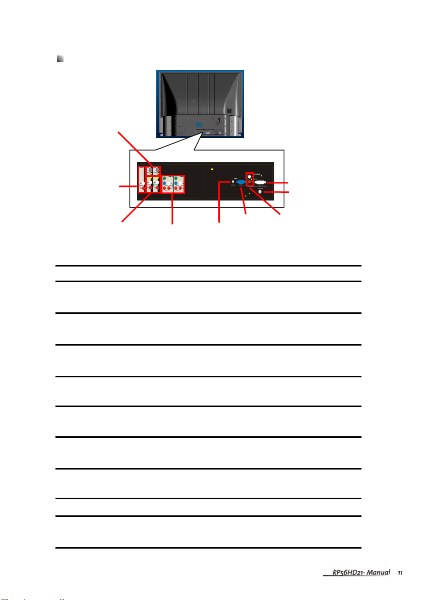
Back Connections
Connector Description
S-Video Connects to an S-Video device, such as a satellite dish
receiver or digital cable box.
Audio Out Connects to an external audio device, such as anAudio
player.
CompositeAV In Connects to a composite audio/video device, such as a VCR
or DVD player.
ComponentAV In Connects to a component audio/video device, such as a
DVD player or set-top box.
RGBAudio In Connects to the audio on an RGB device, such as a
computer or set-top box.
RGB In Connects to an RGB video device, such as a computer or
set-top box.
DVIAudio In Connects to the audio on a DVI device, such as a computer
or set-top box.
TV/Cable In Connects to a VHF/UHF antenna or cable TV.
DVI In Connects to a DVI video device, such as a computer or
set-top box.
ComponentAV
In (COMP1, COMP2)
CompositeAV
In (AV1,AV2)
A
udi
o
Out
S-Video In
(AV1,AV2)
RGBAudio In
RGB In DVIAudio In
DVI In
TV/Cable In
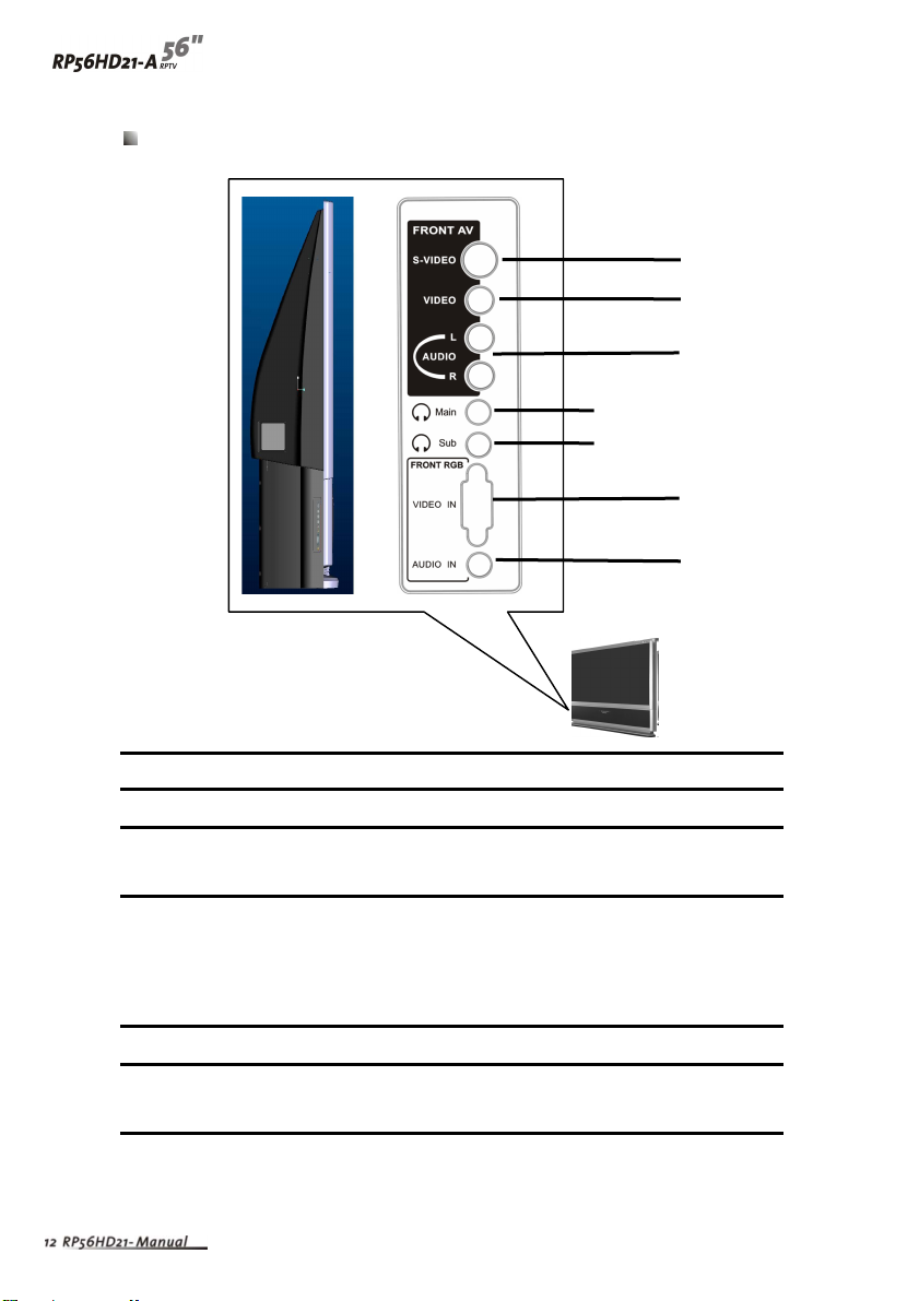
Side Connections
Connector Description
S-Video Connects to an S-Video device, such as a video camcorder.
Video/Audio In Connects to a composite audio/video device, such as a
video camcorder or digital camera.
Main/Sub MAIN: Plug headphone in here to listen to the audio for the
main picture. The built-in speakers are disabled.
SUB: Plug headphones in here to listen to the audio for the
sub-picture.
Video In Connects to an RGB video device, such as a computer.
Audio In Connects to the audio on an RGB device, such as a
computer.
S-VIDEO
VIDEO
Main
L
AUDIO
R
Sub
VIDEO IN
A
UDIO IN

Connecting Components
Read this chapter to lean how to connect :
DVD Players
HDTV decoder set-top boxes
VCRs
Off-airTV and cable TV
External audio devices
Computers
Warning Before connectingany external components, unplug your Micro
Chip Display Projection TV.
Understanding Video Connections
Your Micro Chip Display ProjectionTV has four types of standard video connections.
You should use the best connection available to get the best display. For example, if
your DVD player supports a component video connection, connect the DVD Player
to your Micro Chip Display Projection TV using component video instead of
composite video or S-Video.
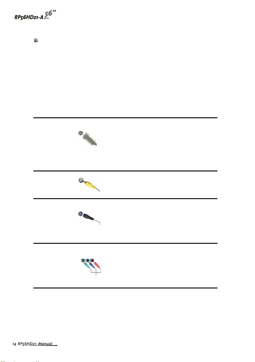
Connection Cable and Description
Quality Connector
Base Coaxial (RF). The video and audio signals are
both carried in one cable (the other three
connection types only handle video, and
require separate connections for sound).
Coaxial is the only way to connect an antenna
to your RPTV.
Good Composite. The video signal is carried through
a single “pin.” This connection method is the
one that is most commonly found on devices.
Better S-Video. The video signal is split into two
signals, black-and-white and color. Text
displayed on-screen through this connection
will be noticeablysharper than composite or
coaxial (RF).
Best Component. The video signal is split into three
signals, two colors, and one black-and-white.
Use component video to take advantage of the
superior picture provided by signal such
sources as HDTV and progressive DVD.
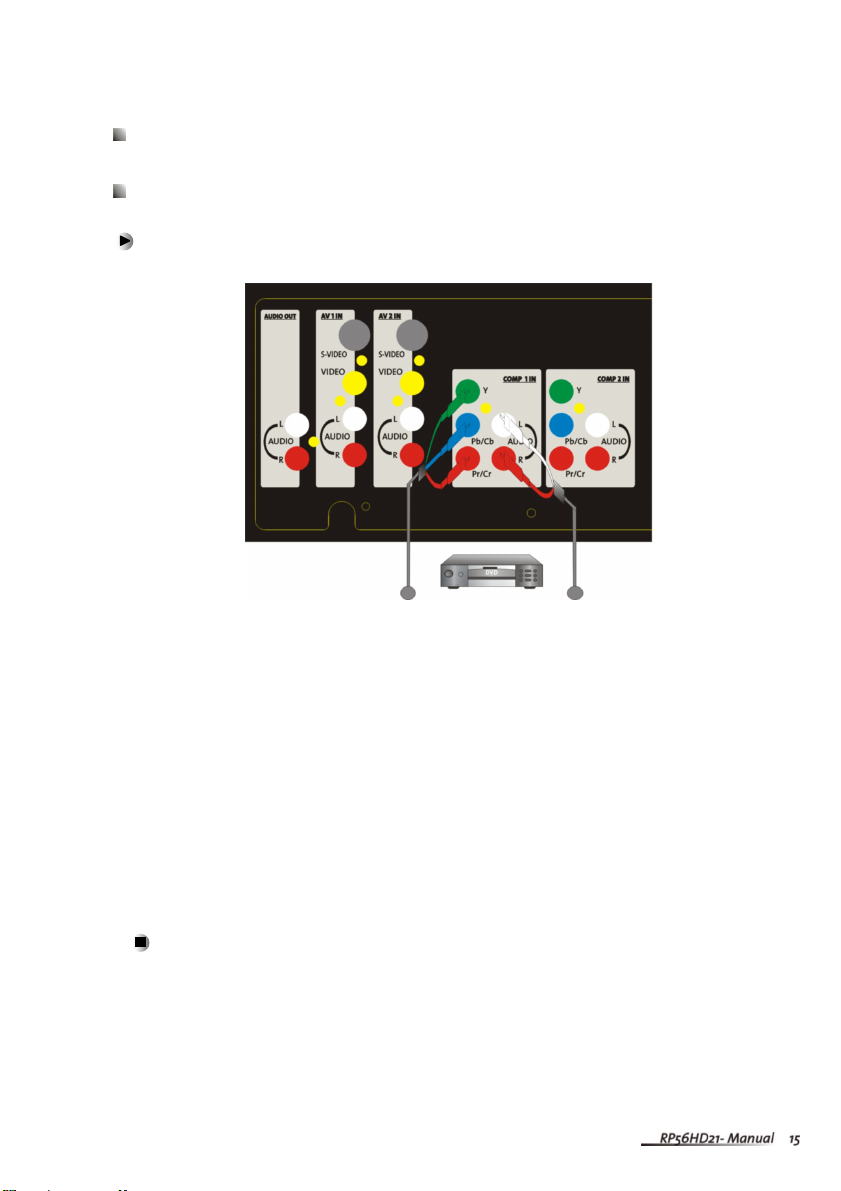
Connecting your DVD Player
Using Component Video
To connect your DVD player using component video :
1 Connect the green-colored Yjack on the back of your DVD player to the
green-colored Yjack on the back of your RPTV.
2Connect the red-colored PRor CRjack on the back of your DVD player to the
red-colored PR/CRjack on the back of your RPTV.
3Connect the blue-colored PBor CBjack on the back of your DVD player to the
blue-colored PB/CBjack on the back of your RPTV.
4Connect the red (R) and white (L) audio jacks on the back of your DVD player to
the R and Laudio-in jacks on the back of your RPTV.
5Select COMP 1 using the INPUT button on the front of your RPTV.
Video Audio
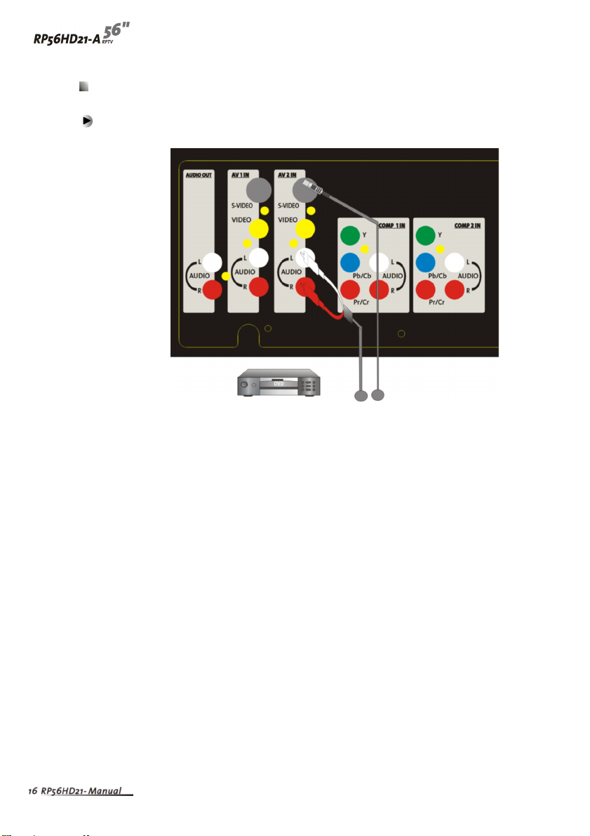
Using S-Video
To connect your DVD player using S-Video :
1Connect the S-Video jack on the back of your DVD player to the S-VIDEO jack
on the back of your RPTV.
2Connect the red (R) and white (L) audio jacks on the back of your DVD player to
the R and Laudio-in jacks on the back of your RPTV.
3 Select AV 2 using the INPUT button on the front of your RPTV.
A
udi
o
Vide
o
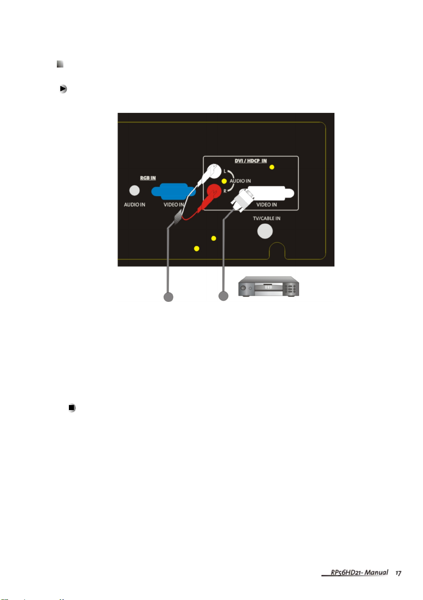
Using DVI Video
To connect your DVD player using DVI video :
1Connect the DVI connector on your DVD player to the DVI-In connector on the
back of your RPTV.
2 Connect theAudio Out jack on your DVD player to the DVIAudio In jacks on the
back of your RPTV.
3SelectDVI using the INPUT button on the front of your RPTV.
The DVI port supports High-bandwidth Digital Content Protection (HDCP).
HDCP encrypts the transmission between the video source and the digital display
for added security and protection.
Connecting the Micro Chip Display ProjectionTV and DVD player by using
HDMI/DVI cable can show you the high definition Display.
Please refer to page 46~48 as the related resolution supported timing table.
Audio Video
Other manuals for RP56HD21-A
1
Table of contents
Other Vivitek Projection TV manuals


