Vivo Link VLHDMIEXTFIB User manual

VLHDMIEXTFIB
HDMI 2.0 Fiber Optical Extender
All Rights Reserved
Version: VLHDMIEXTFIB_2022V1.0
User Manual

HDMI 2.0 Fiber Optical Extender
Preface
Read this user manual carefully before using the product. Pictures shown in this
manual are for reference only. Different models and specifications are subject to real
product.
This manual is only for operation instruction, please contact the local distributor for
maintenance assistance. The functions described in this version were updated till June,
2019. In the constant effort to improve the product, we reserve the right to make
functions or parameters changes without notice or obligation. Please refer to the
dealers for the latest details.
FCC Statement
This equipment generates, uses and can radiate radio frequency energy and, if not
installed and used in accordance with the instructions, may cause harmful interference
to radio communications. It has been tested and found to comply with the limits for a
Class B digital device, pursuant to part 15 of the FCC Rules. These limits are designed
to provide reasonable protection against harmful interference in a commercial
installation.
Operation of this equipment in a residential area is likely to cause interference, in which
case the user at their own expense will be required to take whatever measures may be
necessary to correct the interference.
Any changes or modifications not expressly approved by the manufacture would void
the user’s authority to operate the equipment.

HDMI 2.0 Fiber Optical Extender
SAFETY PRECAUTIONS
To ensure the best performance from the product, please read all instructions carefully
before using the device. Save this manual for further reference.
⚫Unpack the equipment carefully and save the original box and packing material for
possible future shipment.
⚫Follow basic safety precautions to reduce the risk of fire, electrical shock and injury
to persons.
⚫Do not dismantle the housing or modify the module. It may result in electrical shock
or burn.
⚫Using supplies or parts not meeting the specifications of product may cause
damage, deterioration or malfunction.
⚫Refer all servicing to qualified service personnel.
⚫To prevent fire or shock hazard, do not expose the unit to rain, moisture or install
this product near water.
⚫Do not put any heavy items on the extension cable in case of extrusion.
⚫Do not remove the housing of the device as opening or removing housing may
expose you to dangerous voltage or other hazards.
⚫Install the device in a place with fine ventilation to avoid damage caused by
overheat.
⚫Keep the module away from liquids.
⚫Spillage into the housing may result in fire, electrical shock, or equipment damage.
If an object or liquid falls or spills on to the housing, unplug the module immediately.
⚫Do not twist or pull by force ends of the optical cable. It can cause malfunction.
⚫Do not use liquid or aerosol cleaners to clean this unit. Always unplug the power to
the device before cleaning.
⚫Unplug the power cord when left unused for a long period of time.
⚫Information on disposal for scrapped devices: do not burn or mix with general
household waste, and please treat them as normal electrical wastes.

HDMI 2.0 Fiber Optical Extender
Elektro- und Elektronikgeräte
Informationen für private Haushalte
Das Elektro- und Elektronikgerätegesetz (ElektroG) enthält eine Vielzahl von
Anforderungen an den Umgang mit Elektro- und Elektronikgeräten. Die wichtigsten
sind hier zusammengestellt.
1. Getrennte Erfassung von Altgeräten
Elektro- und Elektronikgeräte, die zu Abfall geworden sind, werden als Altgeräte
bezeichnet. Besitzer von Altgeräten haben diese einer vom unsortierten
Siedlungsabfall getrennten Erfassung zuzuführen. Altgeräte gehören insbesondere
nicht in den Hausmüll, sondern in spezielle Sammel- und Rückgabesysteme.
2. Batterien und Akkus sowie Lampen
Besitzer von Altgeräten haben Altbatterien und Altakkumulatoren, die nicht vom
Altgerät umschlossen sind, sowie Lampen, die zerstörungsfrei aus dem Altgerät
entnommen werden können, im Regelfall vor der Abgabe an einer Erfassungsstelle
vom Altgerät zu trennen. Dies gilt nicht, soweit Altgeräte einer Vorbereitung zur
Wiederverwendung unter Beteiligung eines öffentlich-rechtlichen Entsorgungsträgers
zugeführt werden.
3. Möglichkeiten der Rückgabe von Altgeräten
Besitzer von Altgeräten aus privaten Haushalten können diese bei den Sammelstellen
der öffentlich-rechtlichen Entsorgungsträger oder bei den von Herstellern oder
Vertreibern im Sinne des ElektroG eingerichteten Rücknahmestellen unentgeltlich
abgeben.Rücknahmepflichtig sind Geschäfte mit einer Verkaufsfläche von mindestens
400 m²für Elektro- und Elektronikgeräte sowie diejenigen Lebensmittelgeschäfte mit
einer Gesamtverkaufsfläche von mindestens 800 m², die mehrmals pro Jahr oder
dauerhaft Elektro- und Elektronikgeräte anbieten und auf dem Markt bereitstellen. Dies
gilt auch bei Vertrieb unter Verwendung von Fernkommunikationsmitteln, wenn die
Lager- und Versandflächen für Elektro- und Elektronikgeräte mindestens 400 m²
betragen oder die gesamten Lager- und Versandflächen mindestens 800 m²betragen.
Vertreiber haben die Rücknahme grundsätzlich durch geeignete
Rückgabemöglichkeiten in zumutbarer Entfernung zum jeweiligen Endnutzer zu

HDMI 2.0 Fiber Optical Extender
gewährleisten. Die Möglichkeit der unentgeltlichen Rückgabe eines Altgerätes besteht
bei rücknahmepflichtigen Vertreibern unter anderem dann, wenn ein neues
gleichartiges Gerät, das im Wesentlichen die gleichen Funktionen erfüllt, an einen
Endnutzer abgegeben wird. Wenn ein neues Gerät an einen privaten Haushalt
ausgeliefert wird, kann das gleichartige Altgerät auch dort zur unentgeltlichen Abholung
übergeben werden; dies gilt bei einem Vertrieb unter Verwendung von
Fernkommunikationsmitteln für Geräte der Kategorien 1, 2 oder 4 gemäߧ2 Abs. 1
ElektroG, nämlich „Wärmeüberträger“, „Bildschirmgeräte“ oder „Großgeräte“ (letztere
mit mindestens einer äußeren Abmessung über 50 Zentimeter). Zu einer
entsprechenden Rückgabe-Absicht werden Endnutzer beim Abschluss eines
Kaufvertrages befragt. Außerdem besteht die Möglichkeit der unentgeltlichen
Rückgabe bei Sammelstellen der Vertreiber unabhängig vom Kauf eines neuen
Gerätes für solche Altgeräte, die in keiner äußeren Abmessung größer als 25
Zentimeter sind, und zwar beschränkt auf drei Altgeräte pro Geräteart.
4. Datenschutz-Hinweis
Altgeräte enthalten häufig sensible personenbezogene Daten. Dies gilt insbesondere
für Geräte der Informations- und Telekommunikationstechnik wie Computer und
Smartphones. Bitte beachten Sie in Ihrem eigenen Interesse, dass für die Löschung
der Daten auf den zu entsorgenden Altgeräten jeder Endnutzer selbst verantwortlich
ist.
5. Bedeutung des Symbols „durchgestrichene Mülltonne“
Das auf Elektro- und Elektronikgeräten regelmäßig abgebildete Symbol einer
durchgestrichenen Mülltonne weist darauf hin, dass das jeweilige Gerät am Ende
seiner Lebensdauer getrennt vom unsortierten Siedlungsabfall zu erfassen ist.

HDMI 2.0 Fiber Optical Extender
Table of Contents
1. Product Introduction...................................................................................................................................1
2. Features...........................................................................................................................................................1
3. Package List ..................................................................................................................................................1
4. Specification...................................................................................................................................................2
5. Panel Description ........................................................................................................................................3
5.1 Transmitter..........................................................................................................................................3
5.2 Receiver...............................................................................................................................................4
6. System Connection ....................................................................................................................................5
7. Troubleshooting & Maintenance ...........................................................................................................9
8. Customer Service......................................................................................................................................10

1. Product Introduction
Thanks for choosing the HDMI 2.0 Fiber Optical Extender which is designed to extend
4K@60HZ 4:4:4 12 bits HDCP encrypted HDMI signal up to 300m via single-mode or
multi-mode(OM3/OM4) fiber or non-HDCP encrypted signal up to 2km via single-mode
fiber.
The extender also allows signal across the fiber cable for bi-directional IR and RS232
control.
2. Features
▪Supports HDMI 2.0 and HDCP2.2.
▪Supports 4K@60 Dolby Vision.
▪Supports HDR.
▪Bi-directional IR and RS232 pass-though.
▪Supports ARC.
▪Transmission distance: 300m with HDCP encrypted signal using via single-mode
or OM3/OM4 multimode. / 2000m with non-HDCP encrypted signal using single-
mode fiber.
3. Package List
▪1x Transmitter
▪1x Receiver
▪2x Power Adapter (12V DC 1A)
▪1x RS232 Cable (3-pin to DB9)
▪1x 3-pin Terminal Block
▪4x Mounting Ears
▪16x Mounting Screws
▪8x Plastic Cushions
▪1x User Manual
Note: Please contact your distributor immediately if any damage or defect in the
components is found.

4. Specification
Transmitter
Input
(1) HDMI IN
Input Connector
(1) Type-A female HDMI
Output
(2) OPTICAL OUT; (1) AUDIO OUT
Output Connector
(2) LC connector; (1) Toslink connector
Control
(1) IR IN; (1) IR OUT; (1) RS232
Control Connector
(2) 3.5mm mini jacks; (1) 3-pin terminal block
Receiver
Input
(2) OPTICAL IN; (1) AUDIO IN
Input Connector
(2) LC connector; (1) Toslink connector
Output
(1) HDMI OUT
Output Connector
(1) Type-A female HDMI
Control
(1) IR IN; (1) IR OUT; (1) RS232
Control Connector
(2) 3.5mm mini jacks; (1) 3-pin terminal block
General
Video Resolution
Up to 4Kx2K 60Hz 4:4:4 HDR
Audio Format
PCM, Dolby Digital, DTS, DTS-HD
HDMI Standard
2.0
HDCP Version
2.2
CEC
Supported
EDID Pass-through
Supported
HPD
Supported
Transmission Distance
≤300m via single-mode or OM3/OM4 multi-mode fiber
cables.
Operation Temperature
-10℃~ +55℃
Storage Temperature
-25℃~ +70℃
Relative Humility
10%-90%
Power Supply
Input: AC 100~240V, 50/60Hz; Output: 12V DC 1A.
Power Consumption
10W
Dimension (W*H*D)
145mm x 21.5mm x 89.5mm
Net Weight
Transmitter: 350g, Receiver: 350g

5. Panel Description
5.1 Transmitter
No.
Name
Description
①
Power LED
Turns red when DC power present.
②
Link status LED
Turns green when the transmitter and receiver link
successful.
③
Work status LED
Turns green when the signal data is transmitted between
transmitter and receiver.
④
Audio Mode
Switch
▪ARC (Default): Switch the audio mode to ARC.
▪AUDIO: Switch the audio mode to AUDIO.
The DIP switch must be worked with another switch on
receiver, for more details, please refer to the 6.system
connection.
⑤
FW
USB port, used for firmware update.
⑥
OPTICAL OUT
Connect to the OPTICAL IN port on receiver via two fiber
cables (A-B; B-A).
⑦
HDMI IN
Connect to HDMI source.
⑧
AUDIO OUT
Connect to audio broadcast device.
⑨
IR IN
Work with far-end IR OUT port on receiver, connect to IR
receiver (with carrier) to collect IR signal to control far-
end display.
⑩
IR OUT
Work with far-end IR IN port on receiver, connect to IR
Emitter to send IR signal to control source device.
⑪
RS232
Makes up bi-directional RS232 pass-through control with
the RS232 port on receiver. If one is connected to control
device (e.g. PC), and the other should be connected to
the third-party that need to be controlled.
⑫
DC 12V
Connect to 12V DC power adaptor.

5.2 Receiver
No.
Name
Description
①
Power LED
Turns red when DC power present.
②
Link status LED
Turns green when the transmitter and receiver link
successful.
③
Work status LED
Turns green when the signal data is transmitted between
transmitter and receiver.
④
Audio Mode
Switch
▪ARC (Default): Switch the audio mode to ARC.
▪AUDIO: Switch the audio mode to AUDIO.
The DIP switch must be worked with another switch on
transmitter, for more details, please refer to the 6.system
connection.
⑤
FW
USB port, used for firmware update.
⑥
OPTICAL IN
Connect to the OPTICAL OUT port on transmitter via two
fiber cables (A-B; B-A).
⑦
HDMI OUT
Connect to HDMI display.
⑧
AUDIO IN
Connect to audio source device.
⑨
IR IN
Work with far-end IR OUT port on transmitter, connect to
IR receiver (with carrier) to collect IR signal to control far-
end source device.
⑩
IR OUT
Work with far-end IR IN port on transmitter, connect to IR
Emitter to send IR signal to control display device.
⑪
RS232
Makes up bi-directional RS232 pass-through control with
the RS232 port on receiver. If one is connected to control
device (e.g. PC), and the other should be connected to
the third-party that need to be controlled.
⑫
DC 12V
Connect to 12V DC power adaptor.

6. System Connection
Usage Precautions:
⚫Make sure all components and accessories included before installation.
⚫System should be installed in a clean environment with proper temperature and
humidity.
⚫All of the power switches, plugs, sockets, and power cords should be insulated and
safe.
⚫All devices should be connected before power on.
There are four connection ways can be chosen via audio mode switch.
Mode
Switch Status
Description
Transmitter
Receiver
①
ARC
ARC
The audio signal is transmitted from the display
back to HDMI IN and AUDIO OUT ports.
②
ARC
AUDIO
The audio signal is transmitted from the AUDIO
IN to HDMI IN and AUDIO OUT ports.
③
AUDIO
ARC
The audio signal is transmitted from the display
back to the AUDIO OUT port.
④
AUDIO
AUDIO
The audio signal is transmitted from the AUDIO
IN to the AUDIO OUT port.
Note: When the switch status is set as mode 1,2 or 3, the amplifier, display must
support ARC.
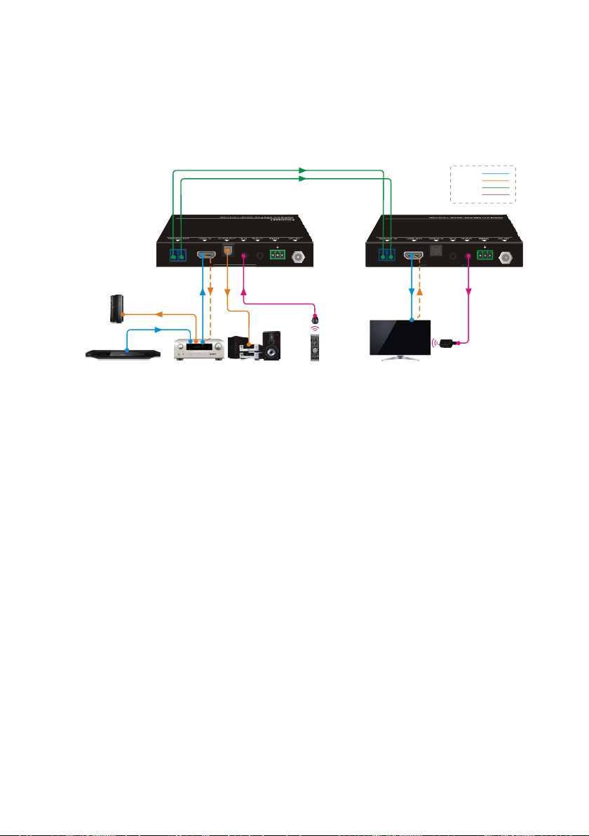
Mode ①: Transmitter: ARC; Receiver: ARC
The audio signal is transmitted from the display back to HDMI IN and AUDIO OUT
ports.
Connection procedure:
Step1.Connect the OPTICAL OUT port of the transmitter to the OPTICAL IN port of
the receiver with two OM3/OM4 multi-mode fiber cables.
Step2.Connect an amplifier to the HDMI IN port of Transmitter, and then connect HDMI
source device (e.g. Blue-ray DVD) and Speaker to the amplifier.
Step3.Connect a broadcast device (e.g. Speaker) to the AUDIO OUT port of
transmitter with toslink audio cable.
Step4.Connect a display device (e.g. TV) to the HDMI OUT port of receiver with HDMI
cable.
Step5.Bi-directional IR control: Both transmitter and receiver have IR IN and IR OUT
port. When one model use for IR signal receiver, the IR signal must be sent out
by the other model.
For example: When IR IN port of transmitter connects with an IR receiver, the IR
Emitter must be connected to the IR OUT port of receiver.
Step6.Bi-directional RS232 control: Both transmitter and receiver have RS232 port.
When one model use for control device, the other must be used for the third-
party device needed to be controlled.
For example: When RS232 port of transmitter connects with a control PC, the
third-party device must be connected to the RS232 port of receiver.
Tx Rx
ARC
BA Tx Rx
ARC
B A
Transmitter : ARC
Blu-Ray DVD Speaker TV Remote
TV Remote
Receiver: ARC
HDMI:
Optical:
Audio:
Control:
300m
APMLIFIER
ARC
ARC
Display
IR Emitter
ARC
Speaker
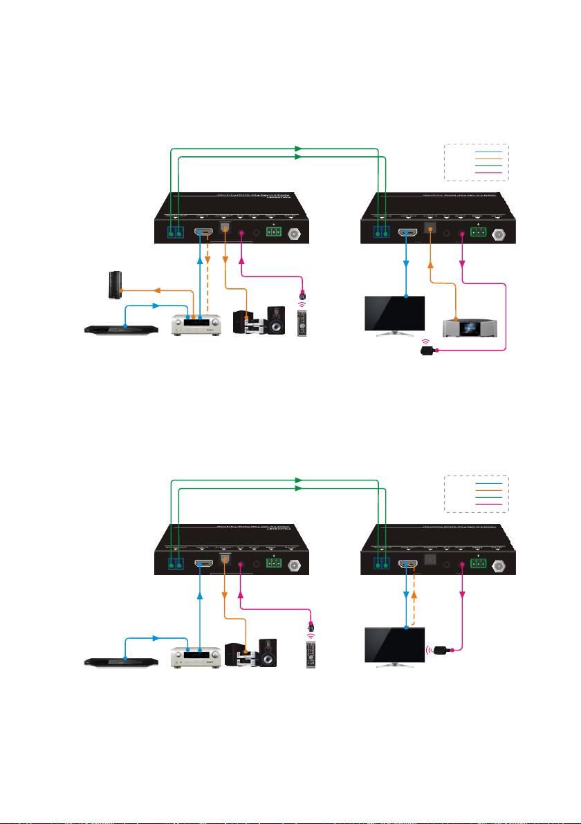
Mode ②: Transmitter: ARC; Receiver: AUDIO
The audio signal is transmitted from the AUDIO IN to HDMI IN and AUDIO OUT ports.
Mode ③: Transmitter: AUDIO; Receiver: ARC
The audio signal is transmitted from the display back to the AUDIO OUT port, but not to
HDMI IN port.
Tx Rx
ARC
BA Tx Rx
ARC
B A
Transmitter: ARC
TV Remote
TV Remote
Receiver:AUDIO
HDMI:
Optical:
Audio:
Control:
300m
Blu-Ray DVD APMLIFIER
ARC ARC
ARC
Display
Speaker
IR Emitter
Digital Radio
Speaker
Tx Rx
ARC
BA Tx Rx
ARC
B A
Transmitter: AUDIO
Speaker TV Remote
TV Remote
Receiver: ARC
HDMI:
Optical:
Audio:
Control:
300m
Display
IR Emitter
ARC
Blu-Ray DVD APMLIFIER

Mode ④:Transmitter: AUDIO; Receiver: AUDIO
The audio signal is transmitted from the AUDIO IN to the AUDIO OUT port.
Tx Rx
ARC
BA Tx Rx
ARC
B A
Transmitter: AUDIO
Blu-Ray DVD Speaker TV Remote
TV Remote
Receiver: AUDIO
300m
Display
IR Emitter
HDMI:
Optical:
Audio:
Control:
Digital Radio

7. Troubleshooting & Maintenance
Problems
Potential Causes
Solutions
Color losing or vague/
double image in HDMI
display.
Poor quality of the optical
fiber cable.
Change for qualified OM3
cable.
Power led is off, No
response for operations
Not been powered.
Power up the unit.
Poor contact.
Make sure power adapter is
in well contact.
No output on the
display.
Source or Display is off.
Turn on the source/ display.
Poor contact.
Check the DVI ports one by
one to make sure they are
in well contact.
The display doesn’t
support the resolution.
Connect the display to the
transmitter and capture its
EDID data before using.
Note: If your problem still remaining after following the above troubleshooting steps,
please contact your local dealer or distributor for further assistance.

8. Customer Service
The return of a product to our Customer Service implies the full agreement of the terms
and conditions hereinafter. There terms and conditions may be changed without prior
notice.
1) Warranty
The limited warranty period of the product is fixed three years.
2) Scope
These terms and conditions of Customer Service apply to the customer service
provided for the products or any other items sold by authorized distributor only.
3) Warranty Exclusions:
⚫Warranty expiration.
⚫Factory applied serial number has been altered or removed from the product.
⚫Damage, deterioration or malfunction caused by:
✓Normal wear and tear.
✓Use of supplies or parts not meeting our specifications.
✓No certificate or invoice as the proof of warranty.
✓The product model showed on the warranty card does not match with the
model of the product for repairing or had been altered.
✓Damage caused by force majeure.
✓Servicing not authorized by distributor.
✓Any other causes which does not relate to a product defect.
⚫Shipping fees, installation or labor charges for installation or setup of the
product.
4) Documentation:
Customer Service will accept defective product(s) in the scope of warranty
coverage at the sole condition that the defeat has been clearly defined, and upon
reception of the documents or copy of invoice, indicating the date of purchase, the
type of product, the serial number, and the name of distributor.
Remarks: Please contact your local distributor for further assistance or solutions.
Other manuals for VLHDMIEXTFIB
1
Table of contents
Other Vivo Link Extender manuals

Vivo Link
Vivo Link VLEXTA170 User manual

Vivo Link
Vivo Link VL120021 User manual

Vivo Link
Vivo Link VLHDMIEXTFIB User manual

Vivo Link
Vivo Link VLHDMIEXT421 User manual

Vivo Link
Vivo Link VL120006 User manual

Vivo Link
Vivo Link VLHDMIEXT422 User manual

Vivo Link
Vivo Link HDBaseT VL120016 User manual

Vivo Link
Vivo Link VLHDMIEXT416 User manual

Vivo Link
Vivo Link VL120007 User manual

Vivo Link
Vivo Link VLHDMIEXTHDB2.0 User manual


