Vivo Link VLHDMIEXT416 User manual

VLHDMIEXT416
4K HDMI Extender with Audio Breakout and
Relay Control
User Manual

2
Statement
Thanks for choosing this product, please read this user manual carefully before using
this product. The functions described in this version are updated till April, 2019. In the
constant effort to improve our product, we reserve the right to make functions or
parameters changes without notice or obligation.
Safety Precaution
Do not dismantle the housing or modify the module to avoid electrical shock or burn.
Using supplies not meeting the products' specifications may cause damage,
deterioration or malfunction.
Do not expose the unit to rain, moisture or install this product near water.
Install the device in a place with fine ventilation.
Do not twist or pull by force ends of the optical cable. It can cause malfunction.
Do not use liquid or aerosol cleaners to clean this unit.
Always unplug the power to the device before cleaning.
Unplug the power when not used for a long period of time.
Refer all servicing to qualified service personnel.
After-sales Service
We provide limited warranty for the product within three years.

3
Product Introduction
Thanks for choosing the 4K HDMI Extender which consists a transmitter and a
receiver. The extender is designed to extend 4K@60Hz 4:2:0 HDMI video to distance
up to 40 meters (131 feet) and 1080P@60Hz video to distances up to 70 meters (230
feet) over a single CATx cable. Bi-directional Power over Cable (PoC) feature allows
the transmitter or receiver to be powered by each other without the need for a nearby
AC power outlet. It supports stereo and multichannel audio on the HDMI ports. In
addition to the audio embedded in the HDMI input stream, the audio is simultaneously
de-embedded to an analog audio output and an S/PDIF audio output.
The extender supports RS232 pass-through to control source or display devices
remotely. It also supports CEC pass-through. Moreover, it provides two RELAY ports
for controlling relay device such as the rise and fall of the projector screen.
Features
Supports HDMI 1.4 and the HDMI video resolution up to 4K@60Hz 4:2:0.
Supports HDCP pass-through and up to HDCP 2.2 version.
Extends 4K@60Hz 4:2:0 signal up to 40m and 1080P@60Hz signal up to 70m via a
single CATx cable.
Supports CEC pass-through.
Supports bi-directional PoC.
Supports bi-directional RS232 pass-through.
Supports RS232 relay control.
Supports audio de-embedding.
Packing List
1x Transmitter
1x Receiver
2x Tx Mounting Ears with 4 Screws
2x Rx Mounting Ears with 4 Screws
4x Tx Plastic Cushions
4x Rx Plastic Cushions
1x Tx 3-pin Terminal Block
3x Rx 3-pin Terminal Blocks
1x RS232 Cable (3-pin to DB9)
1x Power Adapter (24V DC 1.25A)
1x User Manual
Note: Please contact your distributor immediately if any damage or defect in the
components is found.
4
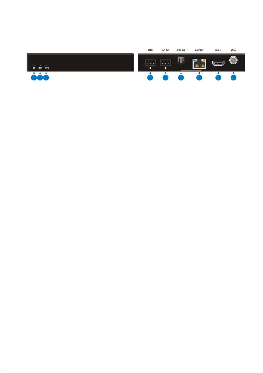
Transmitter Panel Description
1. Power LED: The LED illuminates green when power is applied and is off when no
power is present.
2. LINK LED: The LED illuminates blue when there is a valid HDBaseT connection
with the receiver. The LED is off when there is no valid link.
3. HDMI LED: The LED illuminates blue when there is HDMI video input with HDCP.
It will blink blue when there is HDMI video input without HDCP and will be off
when there is no HDMI video traffic.
4. RS232: 3-pin terminal block for bi-directional RS232 pass-through or RS232 relay
control.
5. L+R OUT: 3-pin terminal block to connect an audio play device (e.g. amplifier) for
audio de-embedding from HDMI input stream.
6. SPDIF OUT: Toslink connector to connect an audio play device (e.g. amplifier) for
audio de-embedding from HDMI input stream.
7. HDBT OUT: RJ45 port to connect the HDBT IN port of receiver by CATx cable.
The HDCP LED illuminates green when the video contains HDCP content, or
blinks green when the video has no HDCP content. The LINK LED illuminates
orange when there is a valid HDBaseT link between the transmitter and the
receiver.
8. HDMI IN:Type-A female HDMI input port to connect an HDMI source device.
9. DC 24V: Locking power port for 24V DC power adapter connection.
L RTx Rx
HDCP LINK
123456789

5
Receiver Panel Description
1. Power LED: The LED illuminates green when power is applied and is off when no
power is present.
2. LINK LED: The LED illuminates blue when there is a valid HDBaseT connection
with the transmitter. The LED is off when there is no valid link.
3. HDMI LED: The LED illuminates blue when the display device (e.g. HDTV) is
connected to the HDMI output port.
4. RS232: 3-pin terminal block for bi-directional RS232 pass-through or RS232 relay
control. The baud rate is fixed 9600.
5. RELAY 1&RELAY 2: Two 3-pin terminal block to connect relay device (e.g.
projector screen) for relay control. Please refer to the chapter RS232 Relay
Control for more details.
6. HDBT IN: RJ45 port to connect the HDBT OUT port of transmitter by CATx cable.
The HDCP LED illuminates green when the video contains HDCP content, or
blinks green when the video has no HDCP content. The LINK LED illuminates
orange when there is a valid HDBaseT link between the transmitter and the
receiver.
7. HDMI OUT: Type-A female HDMI output port to connect an HDMI display device.
8. DC 24V: Locking power port for 24V DC power adapter connection.
Tx Rx NO NCCOM NO NCCOM
HDCP LINK
12345678

6
RS232 Relay Control
In addition to bi-directional RS232 pass-through, the two RS232 ports of the
transmitter and receiver can be used for controlling relay device.
Connect any RS232 port to the control device (e.g. PC) with RS232 cable, and then
install RS232 control software. The relay device can be controlled by sending RS232
commands. Here take the software CommWatch.exe as example:
Double-click the software icon to run this software.
The main view is shown as below:
Baud rate: 9600; Data bit: 8; Stop bit: 1; Parity bit: none.
Please set the parameters of COM number, bound rate, data bit, stop bit and the parity
Parameter configuration area
Monitoring area, show the commands
and its feedback information.
Command sending area
7
bit correctly, and then you are able to send the below commands in command sending
area.
Command
Description
Command and
Feedback Example
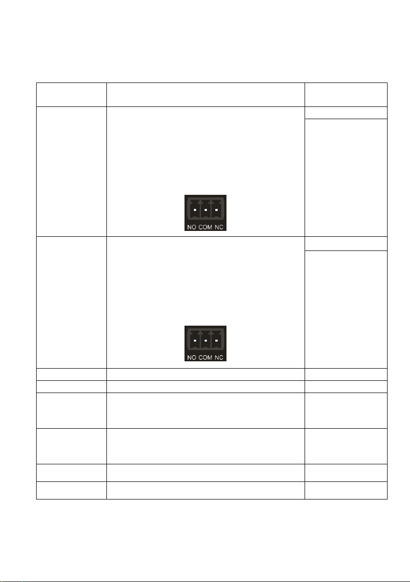
Relay1Wot:[xxx].
Set the RELAY 1 working time to [xxx].
xxx=0~655s.
After sending the command, the Relay 1 port will perform
the below actions:
1) The NO connection closes, and NC connection opens.
2) When the working time is up, the NO connection
opens, and NC connection closes.
Relay1Wot:10.
Set the relay1 to work
for 10 seconds!
1
2
3
4
…
8
9
10
Relay2Wot:
[xxx].
Set the RELAY 2 working time to [xxx].
xxx=0~655s.
After sending the command, the Relay 2 port will perform
the below actions:
1) The NO connection closes, and NC connection opens.
2) When the working time is up, the NO connection
opens, and NC connection closes.
Relay2Wot:10.
Set the relay2 to work
for 10 seconds!
1
2
3
4
…
8
9
10
Relay1Stop.
Immediately stop the work process of relay 1.
Stop relay1 operation!
Relay2Stop.
Immediately stop the work process of relay 2.
Stop relay2 operation!
Relay1Puls.
Relay 1 closes for one second, and then opens.
Set the relay1 to work
for 1 seconds!
Instruction completion
Relay2Puls.
Relay 2 closes for one second, and then opens.
Set the relay2 to work
for 1 seconds!
Instruction completion
Relay1On.
Relay 1 remains closed.
Keep relay 1 closed
Relay2On.
Relay 2 remains closed.
Keep relay 2 closed
Note: When using RS232 pass-through to control the third-party device, the beginning
and end of control commands must be respectively added “@” and “@+”. The format
is: “@........@+”.

8
Technical Specification
VLHDMIEXT416T
Video Input
(1) HDMI
Video Input Connector
(1) Type-A female HDMI
Video Output
(1) HDBT
Video Output Connector
(1) RJ45
Audio Output
(1) L+R OUT, (1) SPDIF OUT,
Audio Output Connector
(1) 3-pin terminal block, (1) Toslink connector
Control
(1) RS232
Control Connector
(1) 3-pin terminal block
VLHDMIEXT416R
Video Input
(1) HDBT
Video Input Connector
(1) RJ45
Video Output
(1) HDMI
Video Output Connector
(1) Type-A female HDMI
Control
(1) RS232, (2) RELAY (1&2)
Control Connector
(3) 3-pin terminal block
General
Video Resolution
Up to 4K@60Hz 4:2:0
HDMI Audio Format
LPCM 7.1 audio, Dolby Atmos®, Dolby® TrueHD, Dolby Digital® Plus,
DTS:X™, and DTS-HD® Master Audio™ pass-through.
Analog (L+R) Audio Format
PCM
SPDIF Audio Format
PCM, Dolby Digital, DTS, DTS-HD
Frequency Response
20Hz–20KHz, ±3dB
THD+N
<0.05%, 20Hz –20KHz bandwidth, 1KHz sine at 0dBFS level (or max
level)
SNR
>90dB, 20Hz-20KHz bandwidth
Crosstalk Isolation
<-70dB, 10KHz sine at 0dBFS level (or max level before clipping)
Noise Level
-90dB
Max Output Level
2.0Vrms ±0.5dB. 2V = 16dB headroom above -10dBV (316mV)
nominal consumer line level signal
L-R Level Deviation
<0.05dB, 1KHz sine at 0dBFS level (or max level before clipping)
Output Load Capability
1KΩ and higher (Supports 10x paralleled 10KΩ loads)
Bandwidth
10.2Gbps
HDMI Standard
1.4
HDCP Version
2.2, 1.4 compliant. Pass-through

9
CEC
Pass-through
EDID
Pass-through
Bidirectional PoC
Supported
Transmission Standard
HDBaseT
Transmission Distance
4K@60Hz 4:2:0 ≤40 meters (131 feet),
1080P@60Hz ≤70 meters (230 feet)
Operation Temperature
-5~ +55℃
Storage Temperature
-25 ~ +70℃
Relative Humidity
10%-90%
Power Supply
Input:100V~240V AC; Output:24V DC 1.25A
Power Consumption
9W (Max)
Dimension (W*H*D)
Tx/Rx: 130mm x 19.5mm x 84.4mm
Net weight
Tx: 260g, Rx:270g
System Connection
The following diagram illustrates the typical input and output connection of the
extender:
Tx Rx NO NCCOM NO NCCOM
HDCP LINK
L RTx Rx
HDCP LINK
Projector
Projector Screen
Control Panel Laptop
Amplifier
Speaker
HDMI:
HDBaset:
Audo:
Control:
CAT Cable
Table of contents
Other Vivo Link Extender manuals

Vivo Link
Vivo Link VLHDMIEXTFIB User manual

Vivo Link
Vivo Link VL120006 User manual

Vivo Link
Vivo Link VLHDMIEXTFIB User manual

Vivo Link
Vivo Link VLHDMIEXTDGL100 User manual

Vivo Link
Vivo Link VLEXTA170 User manual

Vivo Link
Vivo Link VL120021 User manual

Vivo Link
Vivo Link VL120007 User manual

Vivo Link
Vivo Link VLUSBEXT50 User manual

Vivo Link
Vivo Link HDBaseT VL120016 User manual

Vivo Link
Vivo Link VLHDMIEXTHDB2.0 User manual


