Vivo Link VLHDMIMAT4X4 User manual
VLHDMIMAT4X4
4K 4x4 HDMI2.0 Matrix Switcher
All Rights Reserved
Version: VLHDMIMAT4X4_2016V1.0
User Manual

4K 4x4 HDMI2.0 Matrix Switcher
Preface
Read this user manual carefully before using the product. Pictures shown in this manual
is for reference only. Different models and specifications are subject to real product.
This manual is only for operation instruction only. The functions described in this version
are updated till December 11, 2016. In the constant effort to improve our product, we
reserve the right to make functions or parameters changes without notice or obligation.
Please refer to the dealers for the latest details.
Trademarks
Product model, Vivolink and its logo are trademarks of Vivolink. Any other trademarks
mentioned in this manual are acknowledged as the properties of the trademark owner.
No part of this publication may be copied or reproduced without the prior written consent
of Vivolink.
FCC Statement
This equipment generates, uses and can radiate radio frequency energy and, if not
installed and used in accordance with the instructions, may cause harmful interference
to radio communications. It has been tested and found to comply with the limits for a
Class B digital device, pursuant to part 15 of the FCC Rules. These limits are designed
to provide reasonable protection against harmful interference in a commercial
installation.
Operation of this equipment in a residential area is likely to cause interference, in which
case the user at their own expense will be required to take whatever measures may be
necessary to correct the interference
Any changes or modifications not expressly approved by the manufacture would void
the user’s authority to operate the equipment.

4K 4x4 HDMI Matrix Switcher
SAFETY PRECAUTIONS
To insure the best from the product, please read all instructions carefully before using
the device. Save this manual for further reference.
Unpack the equipment carefully and save the original box and packing material for
possible future shipment
Follow basic safety precautions to reduce the risk of fire, electrical shock and injury
to persons.
Do not dismantle the housing or modify the module. It may result in electrical shock
or burn.
Using supplies or parts not meeting the products’ specifications may cause damage,
deterioration or malfunction.
Refer all servicing to qualified service personnel.
To prevent fire or shock hazard, do not expose the unit to rain, moisture or install this
product near water.
Do not put any heavy items on the extension cable in case of extrusion.
Do not remove the housing of the device as opening or removing housing may
expose you to dangerous voltage or other hazards.
Install the device in a place with fine ventilation to avoid damage caused by
overheat.
Keep the module away from liquids.
Spillage into the housing may result in fire, electrical shock, or equipment damage. If
an object or liquid falls or spills on to the housing, unplug the module immediately.
Do not twist or pull by force ends of the optical cable. It can cause malfunction.
Do not use liquid or aerosol cleaners to clean this unit.Always unplug the power to
the device before cleaning.
Unplug the power cord when left unused for a long period of time.
Information on disposal for scrapped devices: do not burn or mix with general
household waste, please treat them as normal electrical wastes.

4K 4x4 HDMI2.0 Matrix Switcher
Contents
1. Introduction.................................................................................................................1
1.1 Introduction to VLHDMIMAT4X4........................................................................1
1.2 Features ............................................................................................................1
1.3 Package List......................................................................................................1
2. Panel Description........................................................................................................2
2.1 Front Panel........................................................................................................2
2.2 Rear Panel.........................................................................................................3
3. System Connection.....................................................................................................4
3.1 Usage Precautions............................................................................................4
3.2 Connection Diagram..........................................................................................4
3.3 Connection Procedure.......................................................................................4
3.4 System Applications ..........................................................................................5
4. Panel Button Control...................................................................................................6
4.1 I/O connection switching....................................................................................6
4.2 EDID Configuration............................................................................................6
4.3 I/O connection Inquiry........................................................................................7
5. IR Control....................................................................................................................8
6. RS232 Control............................................................................................................9
6.1 Installation/uninstallation of RS232 Control Software........................................9
6.2 Basic Settings....................................................................................................9
6.3 RS232 Communication Commands ................................................................10
6.3.1 System Commands...............................................................................10
6.3.2 Lock/unlock Commands........................................................................11
6.3.3 Switching Commands............................................................................11
6.3.4 Scene Commands.................................................................................12
6.3.5 HDCP Compliance ................................................................................12
6.3.6 EDID Configuration................................................................................12
6.3.7 Enable/disable Digital Audio..................................................................14
7. TCP/IP Control..........................................................................................................15
7.1 Control Modes.................................................................................................15
7.2 TCP/IP Communication Software Control........................................................16

4K 4x4 HDMI2.0 Matrix Switcher
7.3 Web-based GUI Control ..................................................................................18
7.3.1 Scene Setting........................................................................................19
7.3.2 I/O connection switching........................................................................20
7.3.3 EDID Configuration................................................................................21
7.3.4 Audio Out...............................................................................................22
7.3.5 Status Setting........................................................................................23
7.3.6 Network Configuration...........................................................................24
7.3.7 Password Modification...........................................................................25
7.4 TCP/IP Port Configuration...............................................................................26
7.5 GUI Update......................................................................................................26
8. Firmware Upgrade through USB port .......................................................................27
9. Specification .............................................................................................................28
10. Panel Drawing ........................................................................................................29
11. Troubleshooting & Maintenance .............................................................................30
12. Customer Service...................................................................................................32

4K 4x4 HDMI2.0 Matrix Switcher
1
1. Introduction
1.1 Introduction to VLHDMIMAT4X4
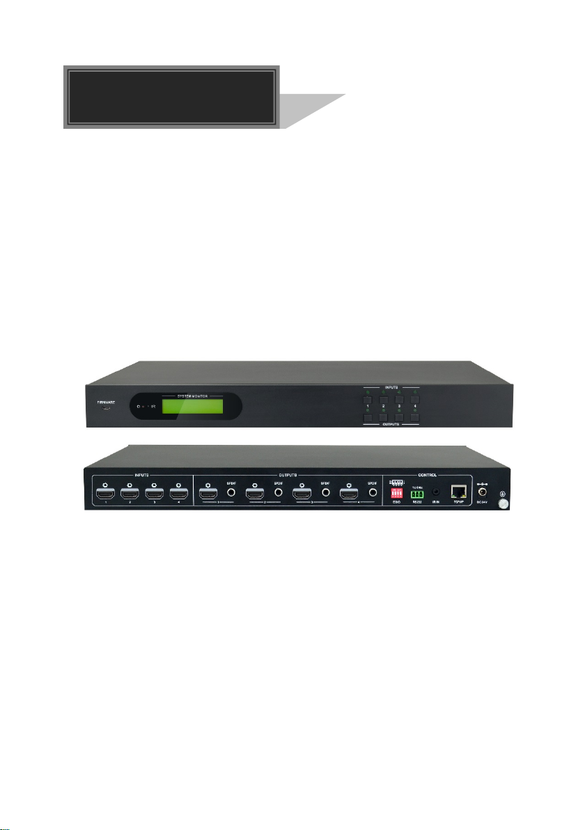
VLHDMIMAT4X4 is a professional 4K 4x4 HDMI2.0 Matrix Switcher with 4 HDMI inputs,
4 HDMI outputs, and 4 SPDIF audio outputs, which is designed for switching four
HDMI2.0 and HDCP2.2 compliant signals. It also provides powerful EDID management
to ensure reliableAV distribution and routing.
You can control the unit via the front panel, IR, RS232, TCP/IP and web-based GUI.
1.2 Features
4 SPDIF ports provide de-embedded HDMI audio output;
Supports 4Kx2K@60Hz 4:4:4 & 1080p 3D signals;
Supports HDMI 2.0, HDCP2.2 compatible, and is backward compatible to the earlier
versions;
Transmits 4Kx2K@60Hz 4:4:4 signal up to 16.4 feet (5m) via HDMI port;
Provides powerful EDID management, built-in EDID can be invoked via DIP switcher
on rear panel, RS232 command or web-based GUI;
Controllable via front panel button, IR, RS232, TCP/IP or web-based GUI;
LCD screen shows real-time I/O connection status;
Convenient firmware upgrade through Micro USB port;
Easy installation with rack-mounting design.
1.3 Package List
1 x VLHDMIMAT4X4
2 x Mounting ears
6 x Screws
4 x Plastic cushions
1 x RS232 cable (3-pin to DB9)
1 x IR receiver
1 x IR remote
1 x Power adaptor(24VDC 1.25A)
1 x User manual
Confirm if the product and the accessories are all included, if not, please contact
with the dealers.
4K 4x4 HDMI2.0 Matrix Switcher
2
2. Panel Description
2.1 Front Panel
Figure 2- 1 Front Panel
No. Name Description
①FIRMWARE Micro USB port for updating firmware.
②Power Indicator
Illuminates red when power on;
Turns green in standby mode;
Blinks red when upgrading.
③IR sensor Built-in IR sensor, receive IR signal sent from IR
remote.
④LCD Screen Displays real-time operation status.
⑤INPUT selector
button Total 4 input selector buttons, press one of buttons to
switch input source.
⑥OUTPUT selector
button Total 4 output selector buttons, press the buttons to
select output channel.
FIRMWARE
INPUTS
OUTPUTS
1 2 3 4
1 2 4 6
35

4K 4x4 HDMI2.0 Matrix Switcher
3
2.2 Rear Panel
Figure 2- 2 Rear Panel
No. Name Description
①INPUTS HDMI input ports, 4 in total, connect with HDMI
sources.
②OUTPUTS SPDIF: audio output ports for de-embedded HDMI
audio, 4 in total.
HDMI: 4 in total, connect with HDMI displays.
③CONTROL
EDID: 4-pin EDID DIP switchers to set EDID data, “1”
stands for “On”, “0” stands for “Off”. Refer to 4.2 EDID
Configurarion for more detials.
RS232: Serial control port, connect with control device.
IR IN: Connects with external IR receiver for using the
IR remote to control the Matrix Switcher.
TCP/IP:
Connect control PC for TCP/IP control.
④DC 24V Connect with 24VDC 1.25A power adaptor.
⑤Ground Connect to ground.
Pictures shown in this manual are for reference only.
1 2 3 4
ON DIP
INPUTS OUTPUTS CONTROL
SPDIF
SPDIFSPDIFSPDIF
12341 42 3
On
Off 1 2 3 4
1
0
Tx Rx
TCP/IPEDID IR IN
R S 2 3 2 DC 24V
45
1 2 3

4K 4x4 HDMI2.0 Matrix Switcher
4
3. System Connection
3.1 Usage Precautions
System should be installed in a clean environment with prop temperature and
humidity.
All of the power switches, plugs, sockets and power cords should be insulated.
All devices should be connected before power on.
3.2 Connection Diagram
Figure 3- 1 Connection diagram
3.3 Connection Procedure
Step1.Connect HDMI sources (e.g. DVD/PS4/Laptop) to HDMI input ports with HDMI
cables;
Step2.Connect HDMI displays (e.g. HDTV/Projector) to HDMI output ports with HDMI
cables;
Step3.Connect speakers/ amplifiers to the SPDIF audio outputs with Toslink cables;
Step4.Connect the RS232 port of control device (e.g. Central Control System, PC) and
VLHDMIMAT4X4 to enable serial control;
Step5.Insert an IR receiver to the IR IN port to control this switcher via IR Remote;
Step6.Connect the TCP/IP port of control device (e.g. Laptop) and VLHDMIMAT4X4 to
enable TCP/IP control;
Step7.Plug a 24VDC power adapter to the DC 24V power port.
1 2 3 4
ON DIP
INPUTS OUTPUTS CONTROL
SPDIFSPDIFSPDIFSPDIF
123 4
1 42 3
On
Off 1 2 3 4
1
0
Tx Rx
TCP/IPEDID IR INR S 2 3 2 DC 12V
Speaker
DVD Laptop HDTV Projector
HDMI:
IR Control:
RS232:
Ethernet:
Audio:
Central Control System Router
Laptop

4K 4x4 HDMI2.0 Matrix Switcher
5
When connecting to HDMI2.0 sources, make sure the HDMI cable is compliant with
HDMI2.0 to ensure reliable transmission;
Connect amplifiers that are capable to decode HDMI audio to the SPDIF ports, or
there will be no output on the amplifiers.
3.4 System Applications
As its good performance in control and transmission, the VLHDMIMAT4X4 can be
widely used in computer realm, monitoring, large screen displaying, conference system,
television education and bank securities institutions etc.

4K 4x4 HDMI2.0 Matrix Switcher
6
4. Panel Button Control
4.1 I/O connection switching
The front panel features four input selection buttons and four output selection buttons for
switching I/O connection.
1) To convert one input to an output:
Example: Input 1 to Output 3
→ Press INPUTS 1 + OUTPUTS 3
2) To convert an input to several outputs:
Example: Convert Input 2 to Output 3 and 4
→ Press INPUTS 2 + OUTPUTS 3 + OUTPUTS 4
NOTE:Indicators of the pressed buttons will blink green for three times if the conversion
is done, then it will be off. If the conversion failed, they will be off immediately.
4.2 EDID Configuration
The rear panel boasts a 4-pin EDID DIP switcher to manage EDID. The EDID data and
its corresponding DIP switcher status are shown in the below list.
DIP Switcher
NO.
Status
EDID
0 0000 Pass-through (default)
1
0001
720P 2D Pass-through CH
2 0010 720P 3D Pass-through CH
3
0011
1080P 2D Pass-through CH
4
0100
1080P 3D Pass-through CH
5 0101 4K@30HZ Pass-through CH
6
0110
4K@30HZ 2.0CH
7 0111 4K@30HZ 7.1CH
8
1000
4K@60HZ 4:2:0 Pass-through CH
9
1001
4K@60HZ 4:2:0 7.1CH
10 1010 4K@60HZ 4:4:4 Pass-through CH
11
1011
4K@60HZ 4:4:4 7.1CH
1111
Enable Software EDID management
mode: RS232 control or Web-based GUI
control

4K 4x4 HDMI2.0 Matrix Switcher
7
4.3 I/O connection Inquiry
Press OUTPUTS button 1, 2, 3 or 4 to inquiry its corresponding input, and then the
indicator of the input button will turn green.

4K 4x4 HDMI2.0 Matrix Switcher
8
5. IR Control
The Matrix Switcher features one built-in IR receiver to receive IR signal from IR remote
to enable IR control. If the external IR receiver or other IR control device need to be
used, the IR IN port on rear panel can be connected.
Here is a brief introduction to the IR remote:
①Standby button, press it to enter/ exit standby mode.
②
INPUTS:
Input channel selection buttons, same with the
corresponding front panel buttons
③
OUTPUTS:
Output channel selection buttons, same with the
corresponding front panel buttons
④
Menu buttons: ALL, EDID, CLEAR and ENTER.
ALL: Select all inputs/outputs.
To convert an input to all outputs:
Example: Input 1 to all Outputs:
→Press INPUTS 1 + ALL + ENTER
EDID management button:
1) One input port learns the EDID data from one output
port.
Example: Input 2 learns EDID data from output 4:
→Press EDID + INPUTS 2 + OUTPUTS 4+ ENTER
2) All input ports learn EDID data from one output port.
Example: All input ports learn EDID data from output 3:
→Press EDID + ALL + OUTPUTS 3 + ENTER
CLEAR: Withdraw button.
ENTER: Confirm operation.

4K 4x4 HDMI2.0 Matrix Switcher
9
6. RS232 Control
6.1 Installation/uninstallation of RS232 Control Software
Installation Copy the control software file to the computer connected with
VLHDMIMAT4X4.
Uninstallation Delete all the control software files in corresponding file path.
6.2 Basic Settings
Firstly, connect VLHDMIMAT4X4 with necessary input devices and output devices.
Then, connect it with a PC installed RS232 control software. Double-click the software
icon to run this software.
Here we take the software CommWatch.exe as example. The icon is showed as below:
Figure 6- 1 Icon of CommWatch
The interface of the control software is showed as below:
Figure 6- 2 Control Interface of CommWatch
Parameter Configuration
Monitoring area, indicates
whether the command
sent works.
Command Sending area

4K 4x4 HDMI2.0 Matrix Switcher
10
Set the parameters (baud rate, data bit, stop bit and parity bit) correctly to ensure
reliable RS232 control.
Baud rate: 9600 Data bit: 8 Stop bit: 1 Parity bit: none
6.3 RS232 Communication Commands
“[“, “]” in the commands are for easy recognition only and not necessary in real
operations. Other symbols including “.”, “,”, “/”, “%”, “;”, “^”. are parts of the
commands.
Feedbacks listed in the column “Feedback Example” are only for reference,
feedbacks may vary according to different operations.
Dial the EDID switcher to “1111” before sending commands pertaining to software
EDID management (with grey background).
6.3.1 System Commands
Command
Function
Feedback Example
/*Type;
Query the model. VLHDMIMAT4X4
/^Version;
Query the version of firmware
VX.X.X
Demo.
Switch to the “demo” mode, convert
input and output in turn like1B1,
1B2, …4B3, 4B4, 1B1… and so
on .The switching interval is 2 seconds.
Demo Mode
AV:01->01
AV:01->02
AV:01->03
AV:01->04
AV:02->01
…
Normal Mode
Undo.
To cancel the current operation. Undo Ok!
PWON.
Work in normal mode.
PWON
PWOFF.
Enter into standby mode, send the
“PWON.” to start.
PWOFF
STANDBY. Enter into standby mode, press other
buttons or send other commands to
start.)
STANDBY
%9962. Query the power status
STANDBY/PWOFF/
PWON
%9964.
Query the IP address. IP:XXX.XXX.X.XXX
%0911.
Reset to factory default.
Factory Default

4K 4x4 HDMI2.0 Matrix Switcher
11
6.3.2 Lock/unlock Commands
Command
Function
Feedback Example
/%Lock;
Lock the front panel buttons. System Locked!
/%Unlock;
Unlock the front panel buttons. System Unlock!
%9961. Query the system locking status. System Locked/
Unlock!
6.3.3 Switching Commands
Command
Function
Feedback Example
[x]All. Transfer signals from the input channel
[x] to all output channels. (x=1~4)
01 To All.
All#. Transfer all input signals to the
corresponding output channels
respectively like 1->1, 2->2…
All Through.
All$.
Switch off all the output channels. All Closed.
[x]#. Transfer signals from the input channel
[x] to the output channel [x]. (x=1~4)
01 Through.
[x]$.
Switch off the output channel [x].
(x=1~4)
01 Closed.
[x]@. Switch on the output channel [x].
(x=1~4)
02 Open.
All@.
Switch on all output channels. All Open.
[x1]V[x2].
Switch the input channel [x1] to one or
several output channels ([x2], separate
output channels with comma).
(x1/x2=1~4)
AV: 02-> 04
Status[x].
Query the I/O connection status of
output [x]. (x=1~4, y=1~4)
AV: Y-> X
(AV: 04-> 01)
Status. Query the input channel to the output
channels one by one.
AV:01->01
AV:01->02
AV:01->03
AV:01->04
%9971.
Query the connection status of the
inputs.
In 01 02 03 04
Connect Y Y Y Y
%9972. Query the connection status of the
outputs.
Out 01 02 03 04
Connect Y Y Y Y
%9975. Query the I/O connection status.
Out 01 02 03 04
In 04 04 04 04
%9976.
Query the output resolution. Resolution

4K 4x4 HDMI2.0 Matrix Switcher
12
Out 1 1920x1080P
Out 2 1920x1080P
Out 3 1920x1080P
Out 4 1920x1080P
6.3.4 Scene Commands
Command
Function
Feedback Example
Save[Y]. Save the present operation to the
preset command [Y], ranges from 1 to
10.
Save To F6
Recall[Y].
Recall the preset command [Y].
Recall From F2
Clear[Y].
Clear the preset command [Y]. Clear F8
6.3.5 HDCP Compliance
Command
Function
Feedback Example
/%[Y]/[X]:[Z].
HDCP management command.
Y=O is for output;
X=1~4 is the number of the port, if the
X=ALL, it means all ports;
Z is for HDCP compliant status, the
value may be 1 (HDCP compliant) or 0
(not HDCP compliant).
/%O/ALL:0.
%0801.
Auto HDCP management, activate
carrier native mode
%0801
%9973. Query the HDCP status of the input
signals. In 01 02 03 04
HDCP Y N Y N
%9974.
Query the HDCP status of the output
signals. Out 01 02 03 04
HDCP Y N Y N
6.3.6 EDID Configuration
The DIP switcher status should be set as 1111 to enable Software EDID management
mode: RS232 control or Web-based GUI control.
Command
Function
Feedback Example
EDIDH[x]B[y].
Input port [y] learns the EDID from
output port [x].
If the EDID data is available and the
audio part supports not only PCM
EDIDH1B1

4K 4x4 HDMI2.0 Matrix Switcher
13
mode, then force-set it to support
PCM mode only. If the EDID data is
not available, then set it as initialized
EDID data.
EDIDPCM[x].
Set the audio part of input port [x] to
PCM format in EDID database.
EDIDPCM[x]
EDIDG[x]. Get EDID data from output [x] and
display the output port number.
Hexadecimal EDID
data and carriage
return character
EDIDMInit.
Restore the factory default EDID data
for each input.
EDIDMInit.
EDIDM[X]B[Y].
Manually EDID switching. Enable
input [Y] to learn the EDID data of
output [X]. If the EDID data is not
available, then set it as initialized
EDID data.
EDIDM3B1
EDID/[x]/[y].
Set the EDID data of input port [x] to
built-in EDID No. [y]. [y] = 0~11,
correspond to the 12 embedded EDID
data separately.
EDID/[x]/[y]
EDIDUpgrade[x]
.
Upgrade EDID data via the RS232
port.
X represents the input port, and x=5
represents all input ports.
When the switcher receives the
command, it will show a message to
prompt you to send EDID file (.bin
file). Operations will be canceled after
10 seconds.
Please send the EDID
file
EDID Upgrade OK!
GetInPortEDID[
X]
Get the EDID data of input [x], [x]=1~4
%9979. Get the DIP switcher status EDID RS232 GUI
CONTROL 1111

4K 4x4 HDMI2.0 Matrix Switcher
14
6.3.7 Enable/disable Digital Audio
Command
Function
Feedback Example
DigitAudioON[x
].
Enable SPDIF audio output port x.
X=1, 2, 3, 4, enable the port x.
X=5, enable all ports.
DigitAudio ON with
[x]/ ALL Outputs
DigitAudioOFF[
x].
Disable SPDIF audio output port x.
X=1, 2, 3, 4, disable the port x.
X=5, disable all ports.
DigitAudio OFF with
[x]/ ALL Outputs
%9977.
Query the status of digital audio of output
channels.
Out 01 02 03 04
Audio Y Y Y Y

4K 4x4 HDMI2.0 Matrix Switcher
15
7. TCP/IP Control
7.1 Control Modes
TCP/IP default settings: IP is 192.168.0.178, Gateway is 192.168.0.1, and Serial Port is
4001. IP can be changed as you need, Serial Port cannot be changed.
Controlled by single PC
Connect a computer to the TCP/IP port of the VLHDMIMAT4X4, and set its network
segment to the same as the default IP of the VLHDMIMAT4X4 (192.168.0.178).
Figure 7- 1 Modify the IP of PC
Controlled by PC(s) in LAN
The VLHDMIMAT4X4 can be connected with a router to make up a LAN with the PC(s),
this make it able to be controlled in a LAN.When control, just make sure the
VLHDMIMAT4X4’s network segment is the same with the router. Please connect as the
following figure for LAN control.
Same network
segment as the
switcher
Table of contents
Other Vivo Link Matrix Switcher manuals


Popular Matrix Switcher manuals by other brands


Network Technologies Incorporated
Network Technologies Incorporated SM-X-15V-LC Series Installation and operation manual

Gefen
Gefen EXT-DVI-16416 user manual

Xantech
Xantech XT-HDBT-MX44-4K-KIT user manual

Roland
Roland VP-42H owner's manual

Avenview
Avenview HDM-C6MX/WIP-SET Software upgrade guide

Atlona
Atlona AT-UHD-PRO3-1616M user manual


