Vivosun WEB-304113-42NJ User manual

USER MANUAL
Grow Tent Kit

Product
Standard Grow Tent 2FTx2FT
VS1000 LED Grow Light
LED Protective Grow Room Glasses
4-Inch 190CFM Inline Duct Fan
4-Inch Carbon Filter
4-Inch 8 ft Ducting
SKU
WEB-304113-42NJ
WEB-LED-100NJ
WEB-306201P-4
WEB-306143-0412J
WEB-306104-48J
4-Inch Clamps
7-Day Digital Timer
WEB-306104-48J
WEB-DT-001J
WEB-LED-100NJ
PRODUCTS INCLUDED IN THIS MANUAL:
CONTENTS PRODUCT CONTENTS
Product Contents
Grow Tent
Key Features
Installation
Specifications
LED Grow Light
Inline Fan
1
2
2
3
9
Key Features
Installation
Specifications
10
11
14
Installation
Specifications
20
20
Instructions
Timer Setting
21
22
Application 15
10
16
7-Day Digital Timer
Safety Information
Warranty
21
32
Equipment Setup 30
33
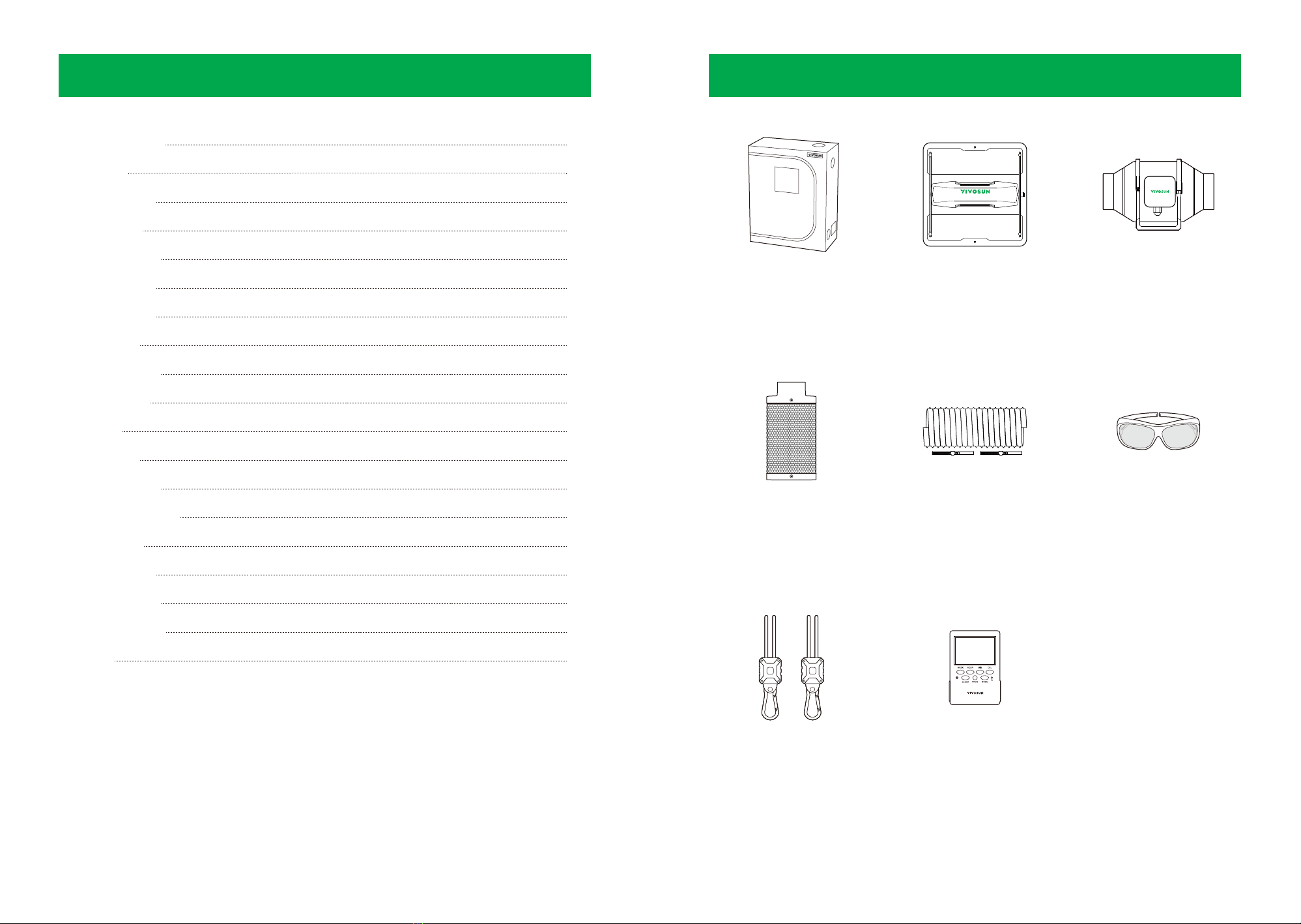
1
Grow Tent
x 1pc
VS Grow Light
x 1pc
Inline Fan
x 1pc
Carbon Filter
x 1pc
Ducting and Clamps
x 1set
7-day Digital Timer
x 1pc
Rope Hangers
x 2pcs
Grow Room Glasses
x 1pc

INSTALLATION
2 3
KEY FEATURES
1. High Light Reflectivity and Containment
Professional-grade canvas designed
with 600D Oxford nylon fabric that
prevents light leaks and an interior
Mylar lining featuring our specialized
''lychee'' patterning that is more
reflective than other patterns.
2. Ducting Openings
Multiple ducting openings with
adjustable size suitable for different
sizes of ductings with no leak of light.
3. Viewing Window
A large window with optional Velcro
cover offers a clear view of your
plants inside the tent without having
to open it up.
4. Heavy-duty Frame
Thick metal poles and connectors
provide a sturdy structure. The ceiling
bars can hold up to 55lbs.
Note: All the devices must be distrib-
uted evenly on the ceilling bars.
5. Waterproof Floor Tray
A waterproof floor tray catches
water, soil, and debris, preventing
leaks.
5
4 pcs.
A
B
C
D
E
F
Frame Poles &Ceiling Bars
1 2
3 4
Corner Supports, 8 pcs.Filter Straps, 2 pcs.
Tent Coat, 1 pc. Floor Tray, 1 pc.
4 pcs.
4 pcs.
4 pcs.
1 pc.
1 pc.
1
32
4
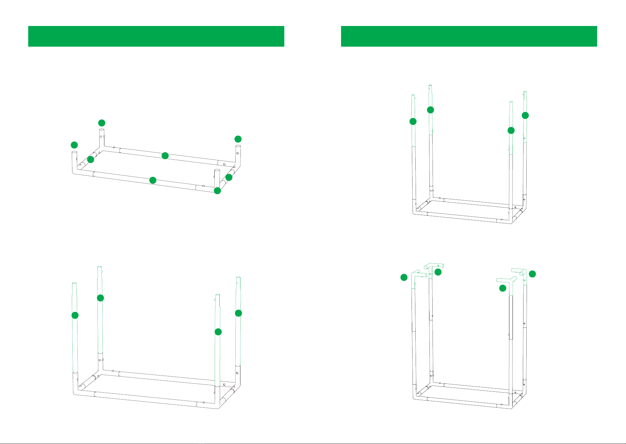
INSTALLATION
4 5
STEP 1 Connect two Poles(A) and two Poles(D) to four Corner Supports(4) to form base
frame of the tent.
STEP 2 Connect four Poles (B) to the Corner Supports (4) of the tent base.
A
D
D
4
4
A
4
4
B
B
B
B
INSTALLATION
STEP 3 Connect four Poles (C) to the Poles (B).
STEP 4 Connect the other four Corner Supports (4) to the Poles (C).
C
C
C
C
4
4
4
4

6 7
STEP 7 Pull the tent roof and cover on the top frame.
STEP 8 Put the Ceiling Bars (E, F) on the top frame for hanging devices.
INSTALLATIONINSTALLATION
STEP 5 Connect two Poles(A) and two Poles(D) to four Corner Supports(4) to form base
frame of the tent.
STEP 6 Unfold the Tent Coat(1) and put the base frame in the bottom of the Tent
Coat(1).
A
A
D
D
1
F
E

SPECIFICATIONS
Dimensions Weight48" x 24" x 60" 20.1 lbs.
8 9
INSTALLATION
STEP 9 Place the Floor Tray (2) into the tent.
STEP 10 Pull the zippers to close the walls and door of the tent.
Warranty Package Size1 Year 49.2'' x 9.6'' x 5.3''
Suggested Plant
Count
Suggested
Lighting
2-4 plants in
3 gallon pots
VS2000
Recommended Doors4'' Inline Fan
6'' Inline Fan
(1) Large Front Door
Vents Windows(2) 11.8'' x 6.3''
Pre-Filter Air Vents
(1) Large Front
Window
Ducting Ports Interior Material(2) 4'' Ducting Ports /
(4) 6'' Ducting Ports /
(1) 8'' Ducting Ports
Mylar 100%Reflective
Exterior Material IncludesOxford Fabric (1) Floor Tray /
(2) Filter Straps
2
INSTALLATION
10 11
1 2
3 4
5 6
KEY FEATURES
1 light can control up to 20 lights with RJ11
serial connection.
1. SAMSUNG LED Diodes
Powered by Samsung high-efficiency diodes
designed to provide the perfect spectrum
for growing plants
2. High Efficacy
High-quality diodes and power supply mean
high PPE, up to 2.7 umol/J.
4. Full Spectrum &FR
380-780nm of full spectrum coverage with
450nm, 660nm and 730nm rich for
photosynthesis.
5. Multiple Lights Control
3. Dimming Control
0-100%light dimming for different growing
stages (except VS1000E).
6. Certification
ETL, CE, FCC certifications and waterproof of
IP65.
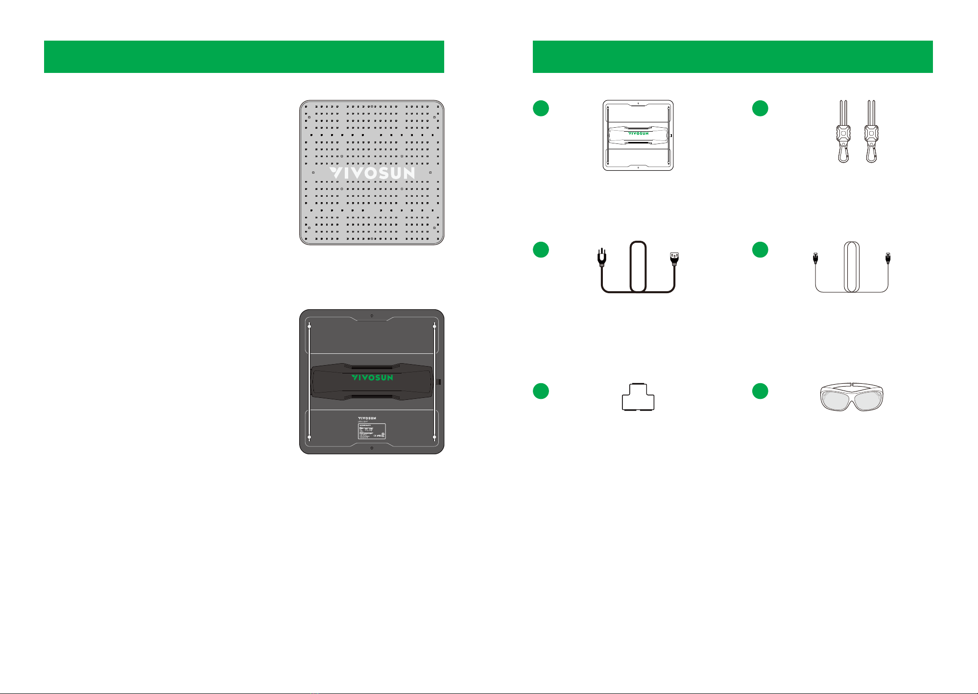
LED Grow Light
x 1pc
Rope Hanger
x 2pcs
Grow Room Glasses
x 1pc
RJ11 3-Way Cable Splitter
x 1pc
Power Cord
x 1pc
RJ11 Network Cable
x 2pcs
12 13
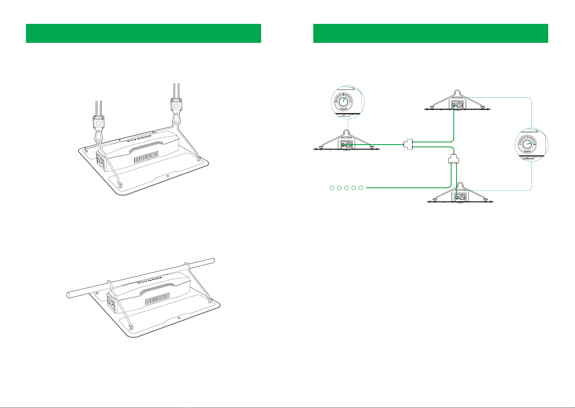
INSTALLATION INSTALLATION
1. Pass the rope hangers' carabiners through the hooks attached to the LED light fixture and
then attach the other end of the rope hangers to the roof of the tent or the ceiling.
2. Unclip the hangers from the LED light fixture and hook them over the crossbar in your tent,
and then reattach the light fixture to the hangers. Choose a light as the master Light (A) and use the RJ11 cables and cable splitter to connect
other lights (B, C) as the controlled Lights as showed above. Turn the dimming knob to the
"EXT" on the controlled light (B, C) and they will be controlled by the master light (A). A
master light can control up to 20 lights.
Note: Ensure all the controlled lights turned to "EXT" and work normally. If connected to a
timer, ensure the total power of all the lights (including the master light and controlled lights)
conform the rated power of the timer.
CONNECTING MULTIPLE LIGHTS
Main Control Light
Controlled Light
Controlled Light
14 15
SPECIFICATIONS
LED Source Samsung LM301D
Input Voltage 120-277V
Power Factor >0.9
Dimensions 11.8'' x 11.8'' x 2.36''
Dimming 25% / 50% / 75% /
100% / OFF / EXT
Frequency 50-60Hz
Input Power 100W
Weight 3.22 lbs.
Lifetime L90>50,000 hours
Warranty 5-Year Standard
Warranty
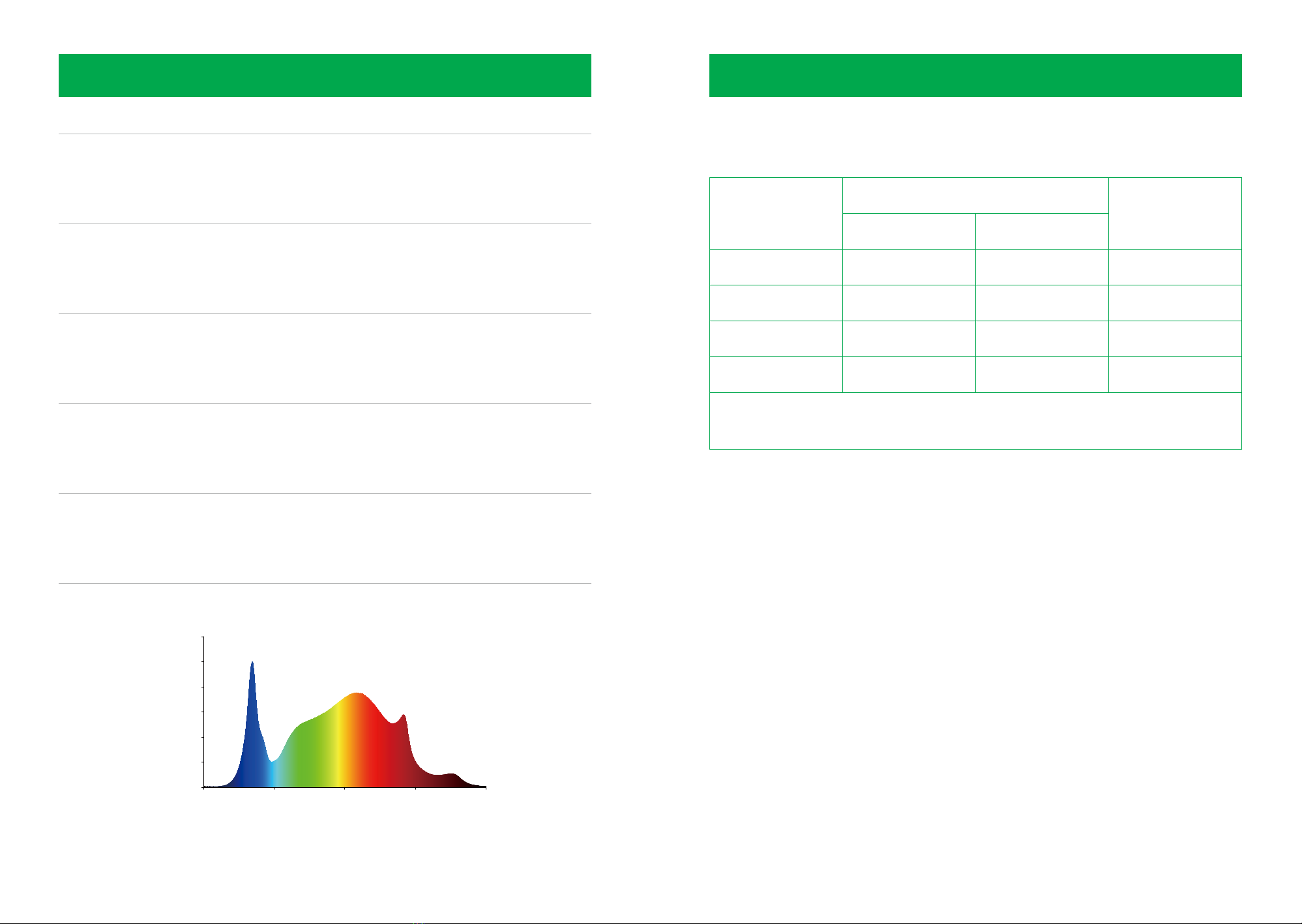
Spectrum Full spectrum: 380 - 780nm; rich 660nm and 730nm
APPLICATION
Wave length (nm)
380
0.0
0.2
0.4
0.6
0.8
1.0
1.2
480 580 680 780
Set the LED in a raised position and place the light further away from your plant to cover a
wider area. Position the light at a lower power closer to your plants for less coverage area
but a more eco-friendly way to grow.
SUGGESTED HANGING DISTANCE & SUGGESTED LIGHTING TIME
Stage
Germination
Seeding
Veg
Flower
Distance
Inch (In.) Centimeter (cm.)
24-30 61-76
61-76
18-24
24-30
12-18
46-61
30-46
Time
18 Hours ON
16 Hours ON
18 Hours ON
12 Hours ON
Note: This suggestion is for reference only, and can be freely adjusted according to the
actual situation.

16 17
INSTALLATION
STEP 1 Loop the two hanging straps around the flanges as shown in the diagram.
STEP 2 Slip the strap through the inner ladder lock slot from the bottom.
STEP 3 Pass the strap into the outer ladder lock slot from the top. Adjust the length of
the completed loop as needed.
INSTALLATION
STEP 4 Tuck the loose end through the center gap of the ladder lock to secure the loop.
STEP 5 Loop the other end of two hanging straps around a pole as showed in picture.
Hang the fan by the duct flanges to secure it. Adjust the height as needed to fit
your space.
A.1 HANGING STRAPS
A. HANGING UPWARD
18 19
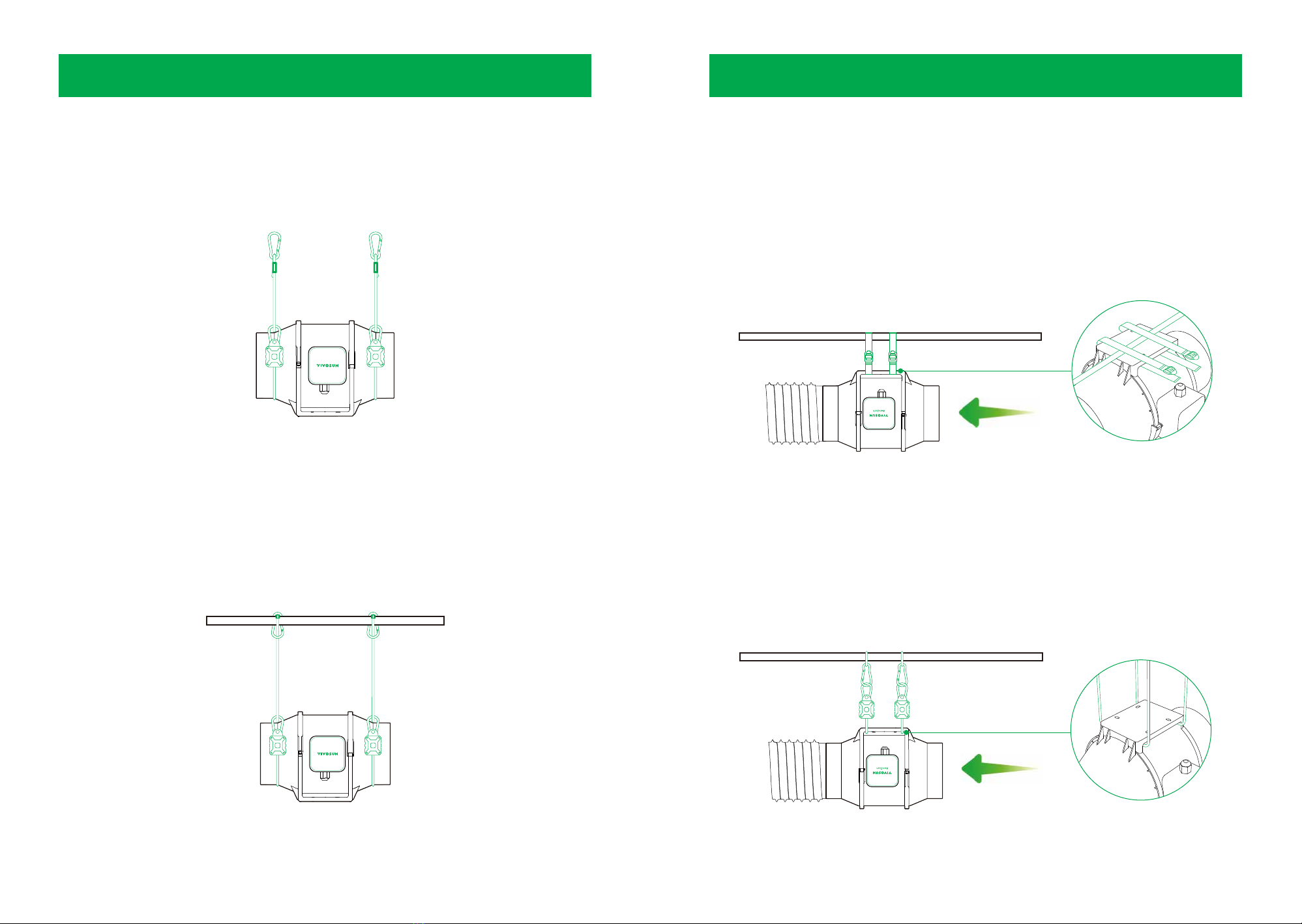
INSTALLATION
STEP 1 Loop the two rope hangers around the flanges as shown in the diagram. Lock
the carabiners to the ropes to secure the fan.
STEP 2 Loop the other end of the rope hangers around the crossbeam as shown in the
diagram. Lock the carabiners to the rope to secure the fan to the pole.
Press the yellow adjustment button to raise and lower the fan to your desired
height.
INSTALLATION
A.2 ROPE HANGERS
Loop the hanging straps around the pole and the flange brackets of the fan. Adjust and
tighten the hanging straps, as show in part A.1, Steps 2-4. Let the fan hang on the pole once
the straps are secure.
B. HANGING DOWNWARD
B.1 HANGING STRAPS
Loop the two rope hangers around the pole and the flange bracket of the fan. Secure the two
hooks to their respective ropes to hang the fan.
Press the yellow button on the rope hanger to adjust the height of the fan to the desired
level.
B.2 ROPE HANGERS

INSTRUCTION
This timer has a built-in backup battery that saves the user's presets and programs.
The timer is designed for indoor use so please ensure that the timer stays dry and is kept
away from water and moisture.
Do not use the timer in temperatures above 131°F or below -14°F.
Do not share the outlet with other appliances if the charge will exceed the maximum load
for that specific outlet.
Heaters, pet feeders, and similar appliances should not be connected to these timers.
Appliances must be turned to ''ON'' before plugging them in to the timer.
Do no attempt to repair, disassemble, or modify the timer under any circumstances.
Keep the timer away from children and pets when you unplug the timer from the outlet.
220V-240V 50Hz (EU, UK, FR, IT, SW, TH, IS, CHI ,VN)
100V-125V 50/60Hz (US)
100V-220V 50/60Hz (BR)
Power Supply
16(13)A 3600W (GR, IT, FR, IS)
13A 3100W (UK)
10(13)A 2300W (SW)
10(13)A 2200W (BR, CHI)
15A 1250W (US)
Power Rating
20 21
SPECIFICATIONS
Diameter 4 Inch
Frequency 60 Hz
Air Flow 190 CFM
Dimensions 11.4'' x 4'' x 8''
Max Ambient
Temp.
110°F/ 45°C
Voltage 120V
Power 59W
Niose 30 dB
Current 0.85A
Speed 2300±10%RPM
1.
2.
3.
4.
5.
6.
7.
8.
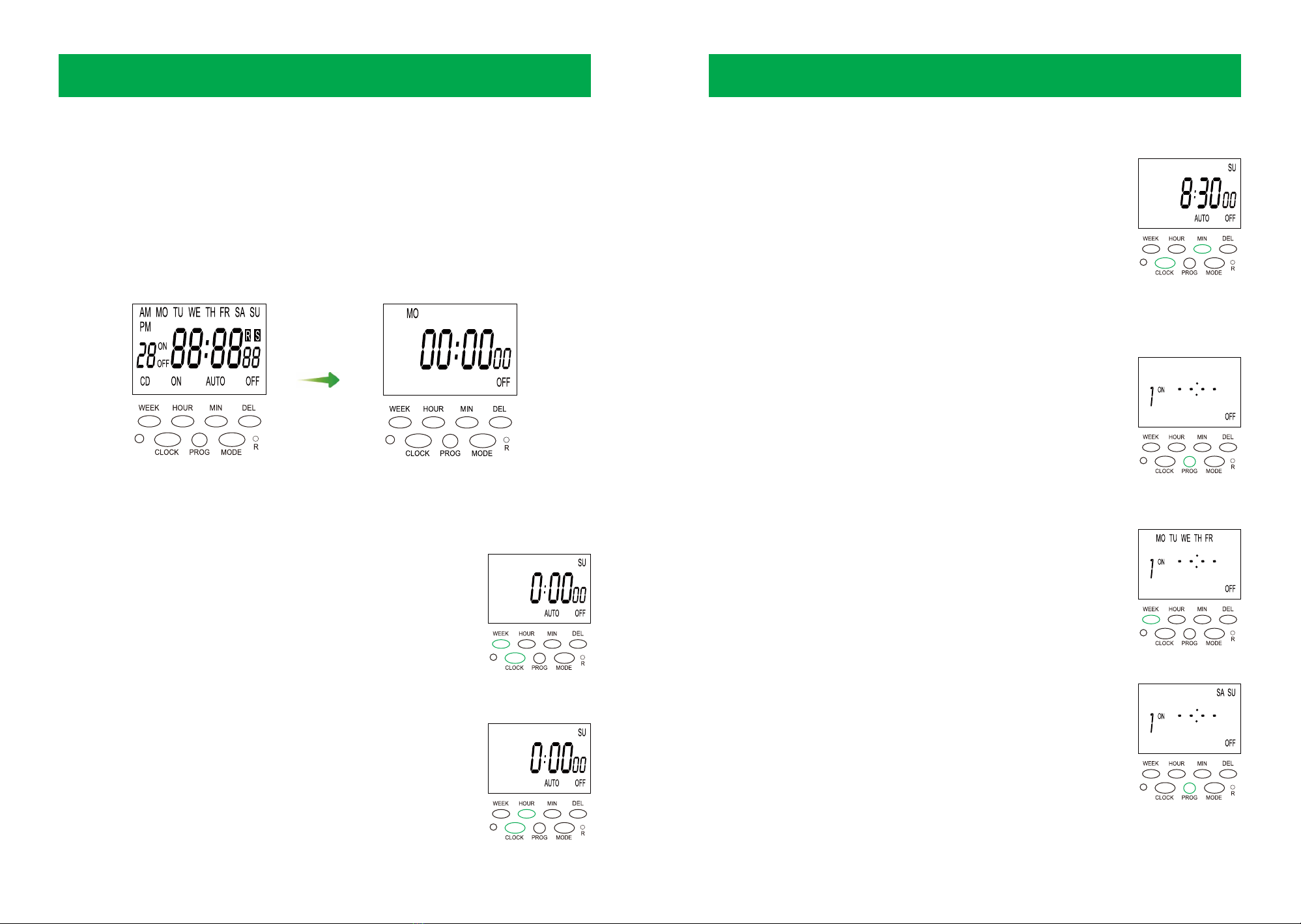
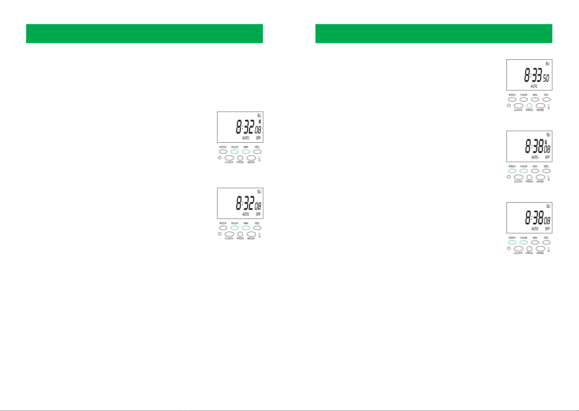
a. Setting ''day''
While pressing the ''CLOCK'' button, press the ''WEEK'' button
to adjust the current day. For example, the current day is
SUNDAY.
b. Setting ''hour''
While pressing the ''CLOCK'' button, press the ''HOUR'' button
to adjust the current hour. For example, the current hour is set
to 08:00.
1. INITIAL SETTINGS
2. SETTING THE CURRENT TIME
3. TIMER PROGRAM SETTING
22 23
TIMER SETTING
Press Reset button ''R'' to reset the timer. The screen will turn blank and show reset display.
Note:
a. If the screen is blank, please plug the timer into a power to charge the battery for 15 to 20
minutes and press ''R'' button to factory mode.
b. Return to factory mode all user's programs &settings will be deleted.
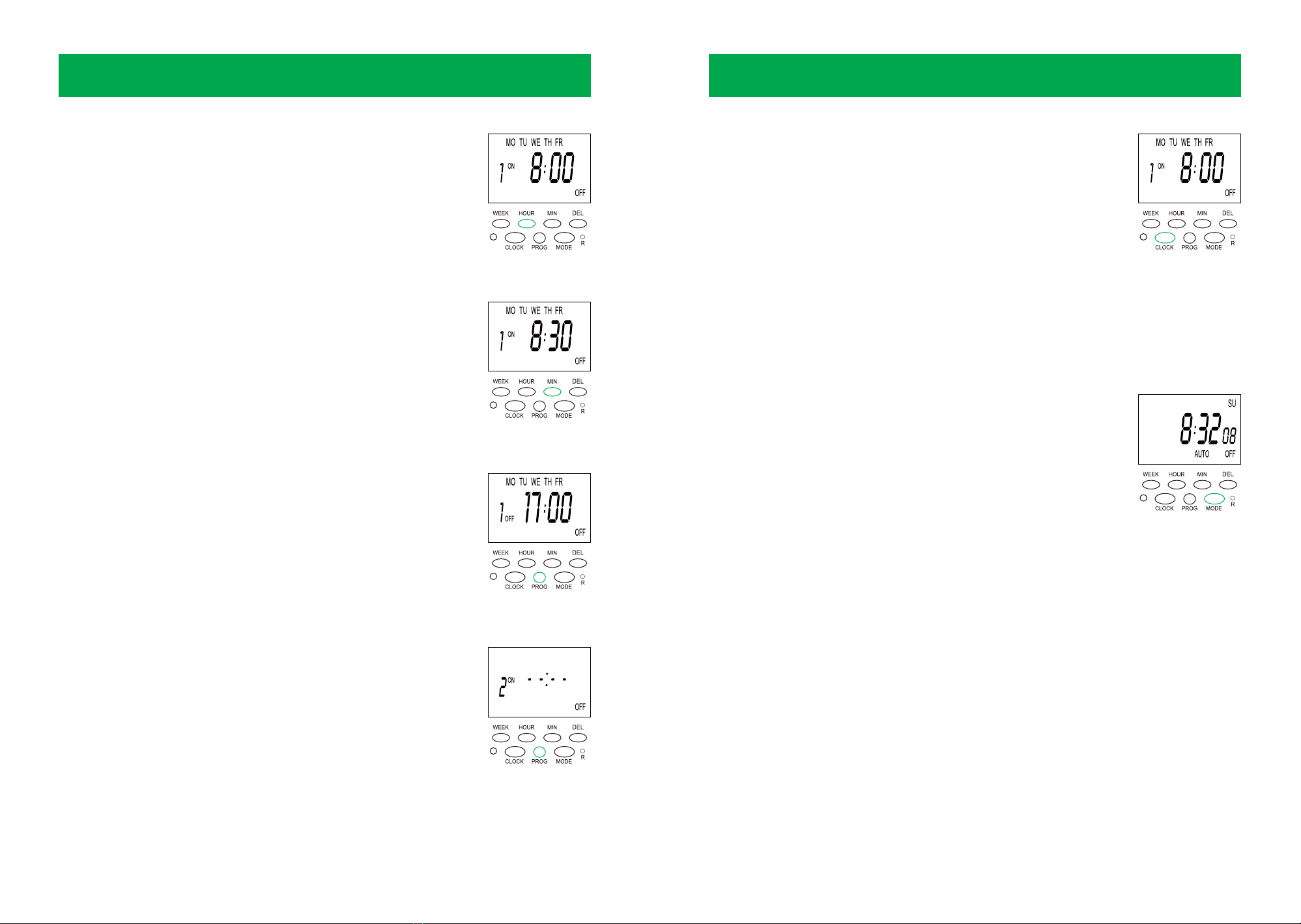
c. Setting ''minute''
While pressing the ''CLOCK'' button, press the ''MIN'' button to
adjust the current minute. For example, the current hour is
08:30.
Press ''PROG'' button to enter ''1 ON'' cycle time setting (first
group ON time).
For example 1ON will show on display.
TIMER SETTING
a.
Press ''WEEK'' button to choose the working day you want.
Note: The combinations of days:
1. MO+TU+WE+TH+FR
2. SA + SU
3. MO+ WE+ FR
4. TU+ TH+ SA
5. MO+ TU+ WE
6. TH+ FR+ SA
7. MO+TU+WE+ TH+ FR+ SA
8.''MO'' or ''TU'' or ''WE'' or ''TH'' or ''FR'' or ''SA'' or ''SU''
b.
4. MODE AND MANUAL OVERRIDE
24 25
TIMER SETTING
Press the ''HOUR'' button and choose the working hour you
need. Long press the ''HOUR'' button (about 3 seconds) to
change the hour number.
c.
Press the ''MIN'' button and choose the working minute you
need. Long press the ''MIN'' button (about 3 seconds) to
change the min number.
d.
After finishing the ''1ON'' setting, press the ''PROG'' button to
enter the ''1OFF'' time setting program. Repeat steps b-d to
finish the ''1OFF'' setting.
e.
Press the ''PROG'' button to switch to the next ON/OFF
group. Repeat steps b-e to set more timing programs as is
needed.
NOTE: The max number of preset groups is 20 ON/OFF
cycles.
f.
TIMER SETTING
Press the ''CLOCK'' button to exit the program setting and
return to the current time.
NOTE: Press the ''PROG'' button repeatedly to review the
program settings you have created. Press the ''DEL'' button
to delete the program or press the ''DEL'' button to restore a
previous program.
g.
Press the ''MODE'' button to advance to the next program, or it
will turn the timer to ON, OFF, or AUTO.
OFF: Always OFF (turns the timer function off).
AUTO: Turns the timer to automatically follow the preset
programs.
ON: Always ON (the device and timer function stay on).
NOTE:
1. When the OFF mode changes to AUTO, the power will stay off
until the next ON cycle. When the timer is in ON mode, the timer
will begin operating according to your program. For example, if
you turn the device to AUTO at 8pm, but your next ON time
begins at 8am, the device will stay OFF until 8am.
2. When the ON mode changes to AUTO, the power will stay
ON until the next OFF cycle. When the timer is in ON mode, the
timer will begin operating according to your program. For
example, if you turn the device to AUTO at 8pm, but your next
OFF time begins at 8am, the device will stay ON until 8am.
Press the ''MODE'' button to set the MODE to AUTO (timer
function).
26 27
TIMER SETTING TIMER SETTING
Random function setting: Check and ensure that the
programs have been set correctly and the timer is set to
AUTO mode. NOTE: If the timer is not in AUTO mode please
set it according to section 4.
a.
Press ''WEEK'' and ''HOUR'' at the same time to enter random
mode, will show ''R'' on the display.
b.
Press ''WEEK'' and ''HOUR'' to cancel the random mode, ''R''
will disappear from the display and exit random mode.The
timer will work as user previous programs setting.
c.
a. Setting daylight savings time:
Press ''HOUR'' and ''MIN'' to set daylight savings time. ''S'' will be
displayed on the screen. The current time will be set to one hour
ahead.
b. Cancel and exit daylight savings time
Press ''HOUR'' and ''MIN'' to cancel daylight savings time. The
''S'' will disappear and you will exit daylight savings time.
5. DAYLIGHT SAVINGS TIME
This function allows the timer to adjust for daylight savings time automatically.
6. ANTI-THEFT RANDOMIZATION FUNCTION
he timer will operate the plugged-in appliance with a random ON/OFF cycle pattern,
which is useful for being away from home to make outsiders believe someone is at home.
In random mode, the timer will turn ON and OFF randomly in 10 - 42 minute variations
based on an ON/OFF schedule that you set.
The random function can only work when the timer program has been set and the mode is
in AUTO mode.
7. COUNTDOWN FUNCTION
This function allows a plugged-in appliance to turn ON or OFF during countdown period.
The user can set the countdown duration (1sec-99H59min59sec).
1.
2.
3.
28 29
TIMER SETTING
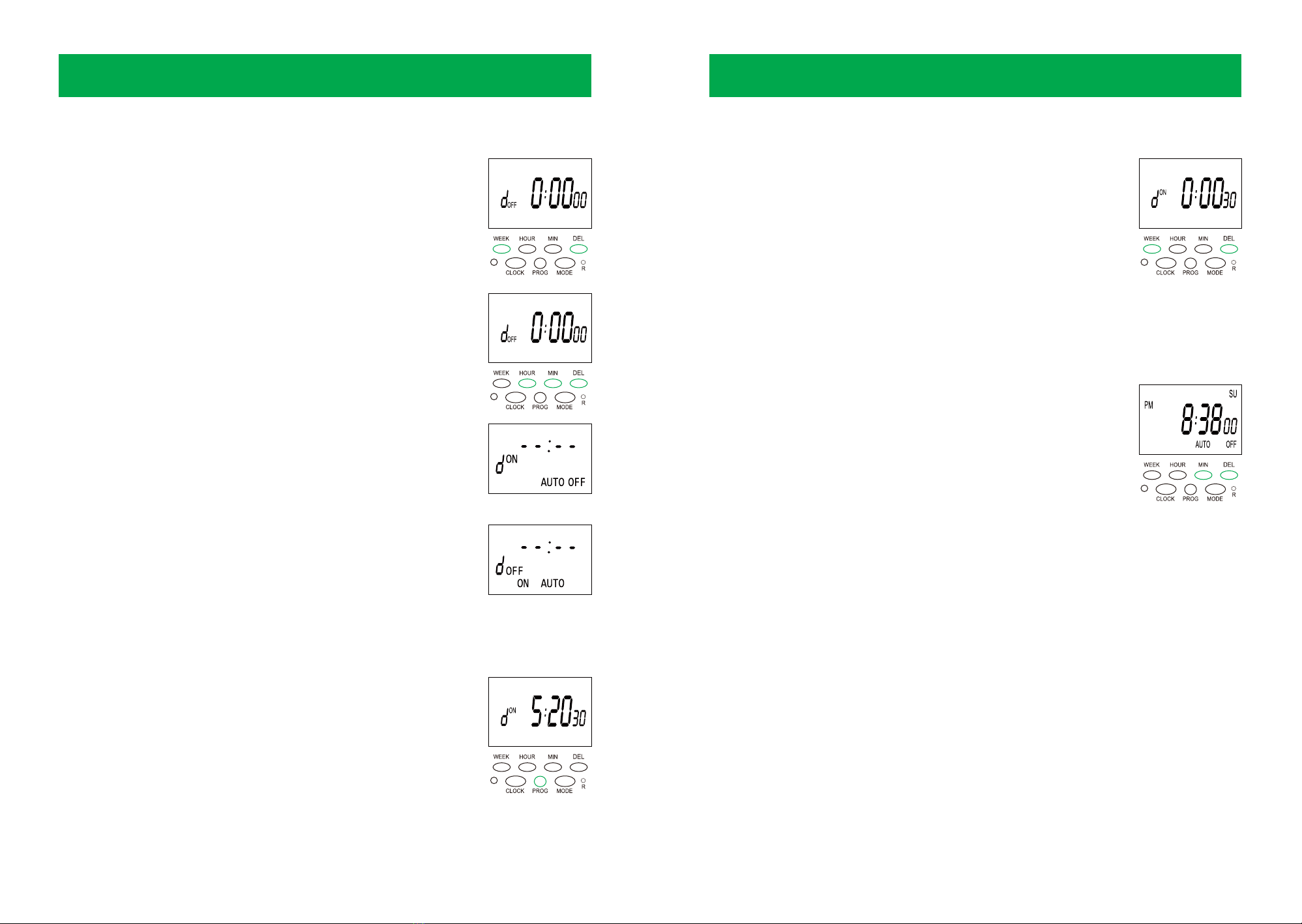
1. Setting a countdown:
a. Long-press WEEK and DEL to enter the countdown setting.
''dOFF 00:00:00'' will be displayed on the screen.
b. Press the ''MODE'' button to switch ON or OFF in countdown
mode. ''dON'' and ''dOFF'' will be displayed on the screen.
c. Press ''HOUR,'' ''MIN,'' and ''DEL'' together to set the hour,
minute, and second countdown time you need.
d. Long press ''HOUR,'' ''MIN,'' and ''DEL'' to adjust the hour,
minute, and second rapidly.
e. Press ''WEEK'' to cancel or recover the countdown setting.
NOTE:
1. While in dON mode, the timer will change to Auto OFF when
the countdown timer completes.
2. While in dOFF mode, the timer will change to Auto ON when
the countdown timer completes.
2. Manual of countdown operation
a. Press ''PROG'' to start the countdown work after finish the
countdown time setting.
b. Press ''PROG'' can pause and continue the countdown during
countdown work.
8. AM & PM DISPLAY MODE
OFF mode Display dON
ON mode Display dOFF
TIMER SETTING
3. Cancel countdown mode
Keep press ''WEEK''and ''DEL'' to cancel the countdown mode at
any time and display will back to current time.
Press ''MIN'' and ''DEL'' at the same time to switch 12/24 hours
display mode, ''AM'' or ''PM'' will show on display when you
choose and set in 12 hours mode. Press ''MIN'' and ''DEL'' to exit
the 12 hours mode.

GROW TENT VENTILATION
Your grow tent has multiple duct openings and
intake holes for ventilation.
Duct Openings: Install ducting through the duct
openings - ensure that the diameter of the
ducting matches the size of your tent. Use the
cinches on the openings to secure the ducting to
the tent.
Intake Air Vent: Introduce fresh air from outside
of the tent through the intake vents at the bottom
of the tent.
INSTALLING THE INLINE FAN
An inline fan is used as an exhaust fan or an
intake fan.
Exhaust fan: Hang or mount your fan in your tent
in the highest corner of the space with the arrow
facing out and away from your tent.
Intake fan: Mount at the bottom corner of your
tent or outside your grow tent, with your arrow
pointing into the tent.
EQUIPMENT SETUPEQUIPMENT SETUP
Exhaust Fan
Intake Fan
TYPICAL SETUP
Inline fan and Carbon filter: Choose an appropriate
inline fan for your tent size. Hang the inline fan from
the crossbars of your tent. Hang the inline fan and
connect it to the carbon filter so that the arrow on
the inline fan points out of the tent and the filter is
positioned so that air is pulled through the filter,
rather than pushed through the filter.
Grow Light: Choose an appropriate grow light for
your tent. Install the grow light with rope hangers
after you have installed the inline fan and carbon
filter. Adjust the light to an appropriate height for
your plants.
30 31
Intake
Air Vent
Ducting Opening

32 33
WARRANTY
The VIVOSUN warranty program is our commitment to you. That the product sold by
VIVOSUN will be free from defects in manufacturing for a period of one years from the date
of purchase. If a product is found to have a defect in material or workmanship within one
years of the date of purchase, we will take the appropriate actions as defined in this warranty
to resolve any issues.
This warranty program applies to any order, purchase, receipt, or use of any products sold by
VIVOSUN or our authorized dealerships. The program covers products that have become
defective, malfunctioned, or has otherwise become unusable. The warranty program goes
into effect on the date of purchase and expires one years from the date of purchase. If your
product becomes defective during that period VIVOSUN will replace your product with a
new one or issue a full refund. This warranty program does not cover defects arising from
abuse or misuse. This includes physical damage, submersion of the product in water,
incorrect installation such as use with the wrong voltage, or misuse for any reason other than
the product's intended purpose. VIVOSUN is not responsible for consequential loss or
incidental damage of any nature caused by the product.
We will not warrant damage from normal wear such as scratches and dings.
BEST QUALITY
If you run into any issues with this product,
contact us and we'll happily issue a
replacement or a full refund!
SAFETY INFORMATION
Handling: Set up the light in an operating environment that allows for adequate air circula-
tion. Never allow objects to obstruct or enter the ventilation openings. Avoid looking directly
at the lights, when they are turned on. Use shielding and grow room glasses to protect your
eyes.
For Indoor use Only: DO NOT use devices in this kit outdoors or in any other location with
hazardous spaces that include flames, explosives, corrosive chemicals, or wet environments.
Appropriate temperature range is -4°F - 104°F.
Power Cord: Your AC cord has a three-wire grounding plug (a plug that has a grounding pin).
This plug fits only a grounded AC outlet. If you're unable to insert the plug into an outlet
because the outlet isn't grounded, contact a licensed electrician to replace the outlet with a
properly grounded one.
Repairs: If there is something wrong with your light, please contact us. Opening the light to
inspect or repair in accordance with VIVOSUN's instructions and express permission will not
affect your existing warranty. However, if you disassemble the light or install add-ons inside
without express permission from VIVOSUN, you may damage the light and void warranty.
Cleaning: DO NOT use water or any detergent to clean this product.
Please read the following information carefully before using. Failure to observe
these safety instructions may result in serious injury and will release VIVOSUN
of all liability and void all product warranties.
Table of contents
Other Vivosun Lawn And Garden Equipment manuals


