VKB T-Rudder User guide

Rudder Pedals TRudder
Installation and setup manual
Version 1.1 от 20.05.2014

©2014 VKB. All rights reserved.
©2014 Written by Victorus. All rights reserved.

1
Content
Introduction . . . . . . . . . . . . . . . . . . . . . . . . . . . . . . . . . . . . . . . . . . . . . . . . . . . . 3
Pedals installation . . . . . . . . . . . . . . . . . . . . . . . . . . . . . . . . . . . . . . .3
1. General info . . . . . . . . . . . . . . . . . . . . . . . . . . . . . . . . . . . . . . . . . . . . . . . . . . 3
2. Order of assembly . . . . . . . . . . . . . . . . . . . . . . . . . . . . . . . . . . . . . . . . . . . . . 4
Support shaft height setup . . . . . . . . . . . . . . . . . . . . . . . . . . . . . . 11
1. General info . . . . . . . . . . . . . . . . . . . . . . . . . . . . . . . . . . . . . . . . . . . . . . . . . 11
2. Order of setup . . . . . . . . . . . . . . . . . . . . . . . . . . . . . . . . . . . . . . . . . . . . . . . 11
Pedals connection . . . . . . . . . . . . . . . . . . . . . . . . . . . . . . . . . . . . . . 12
Pedals axis setup . . . . . . . . . . . . . . . . . . . . . . . . . . . . . . . . . . . . . . . 12
1. General info . . . . . . . . . . . . . . . . . . . . . . . . . . . . . . . . . . . . . . . . . . . . . . . . . 12
2. Axis type . . . . . . . . . . . . . . . . . . . . . . . . . . . . . . . . . . . . . . . . . . . . . . . . . . . 13
3. Axis calibration . . . . . . . . . . . . . . . . . . . . . . . . . . . . . . . . . . . . . . . . . . . . . . 13
4. Axis parameters setup . . . . . . . . . . . . . . . . . . . . . . . . . . . . . . . . . . . . . . . . . 14
5. Response curves . . . . . . . . . . . . . . . . . . . . . . . . . . . . . . . . . . . . . . . . . . . . . 14
Variants of pedals steadiness support. . . . . . . . . . . . . . . . . . . . 15


3
Introduction
TRudder pedals let the virtual pilot to control the rudder just like a real pilot. This
device has not onboard controller and must be connected to the one of the following
devices:
▼CobraZ joystick,
▼Tiny Box external controller,
▼ThrottleBox external controller.
Standard UTP cable with two 8 position connectors 8P8C (often called as RJ45) at
each end is used for pedals connecting.
This manual contains recomendations how to assembly and set up pedals.
Pedals installation
1. General info
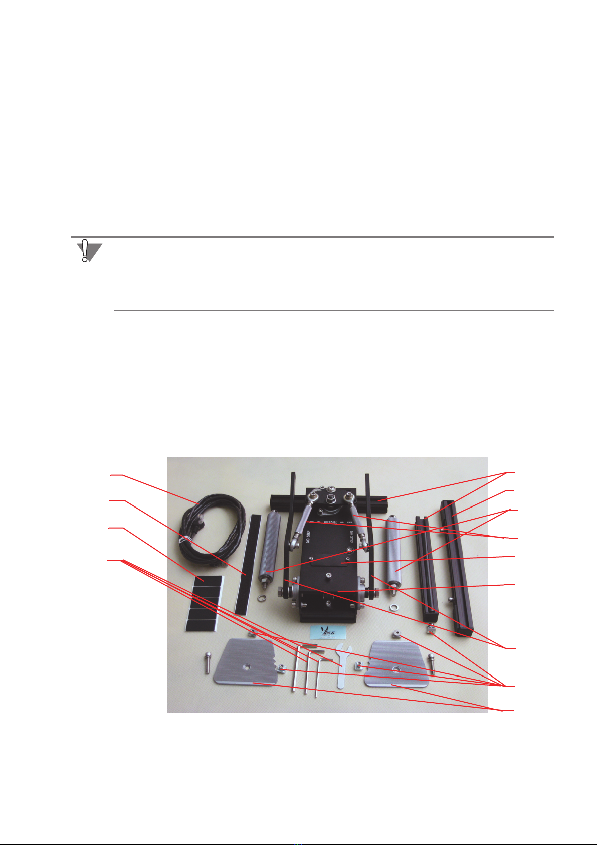
TRudder pedals are delivered partially dizassembled. Delivery set is shown on
fig. 1.1.
1.1.
The same cables are used for connections between many kinds of devises, such as
routers. ADSL modems etc. Do not even try to connect pedals to any device with
8P8C socket! If you connect pedals to any device except above mentioned it will be
damaged.
Рис. 1.1.
4
1
2
3
5
6
7
8
9
10
11
12
13

TRudder pedals. Installation and setup manual
4
The foreleg is temporary replaced with one of the back legs.
2. Order of assembly
You must execute the following operations to assembly the pedals.
1. Unscrew the back leg from the case (fig. 2.2) and take it away.
2.2.
2. Unscrew false panel from the case (fig. 2.3).
2.3.
Табл. 1.1.
Номер Наименование Примечание
1Backlegs
2 Foreleg
3 Support shaft
4Syncronizer
5 False panel
6Case
7Forcelever
8 Shaped nut with screw
9 Foot bearing
10 UTP cable
11 Velcro strip For fixation on the pile surfaces.
12 Silicon legs For installation on the firm and smooth
surfaces.
13 Tool set.
Fig. 2.2.
screw

5
.
3. Prepare back legs for foot bearing installation:
3.1. insert two shaped nuts into internal housing of the leg, M5 nut closer to end
cap, M4 one closer to the center.
3.2. drive a M4 screw into the nut to fix them both in an extreme position (fig. 2.4).
2.4.
4. Attach legs to the case.
4.1. Insert hex tool into the screw head, put spring and plain washers on the screw
body (fig. 2.5).
2.5.
Fig. 2.3.
Fig. 2.4.
Fig. 2.5.

TRudder pedals. Installation and setup manual
6
The back leg is attached to the case by two screws. Three adjustment holes make
possible to set the angle between the case and the leg thus providing pedal setup
for pilot foot size. The screw, drived into the fourth hole, is using as an axis. Before
the leg is fixed in a chosen position you can rotate it around this screw.
4.2. Choose an appropriate adjustment hole and insert the screw with washers into
it (fig. 2.6).
2.6.
4.3. Engage shaped nuts on the screws from the outer side of the case(fig. 2.7)
2.7.
4.4. Insert engaged shaped nuts into internal housing of the leg (fig. 2.8).
2.8.
Fig. 2.6.
adjustment
holes
axis
hole
Fig. 2.7.

7
.
4.5. Screw the back legs to a case using М5х25 screw with spring washer. Drive the
screws into threaded rivet nuts of the axis holes from the external side of the
case (fig. 2.9).
2.9.
4.6. Check the correspondence between the back legs position and your foot size
Change the angle between the leg and the case using another adjustment hole
if needed.
4.7. Tighten the screws. An example of back legs installation is shown on fig. 2.10.
2.10.
Fig. 2.8.
Fig. 2.9.
screw

TRudder pedals. Installation and setup manual
8
4.8. Install false panel to its place.
5. Install foreleg.
5.1. Drive screws with washers out of shaped nuts (fig. 2.11).
2.11.
5.2. Insert unscrewed screws into the holes of the case (fig. 2.12).
2.12.
5.3. Engage screws with shaped nuts of the foreleg (fig. 2.13).
2.13.
Fig. 2.10.
Fig. 2.11.
Fig. 2.12.

TRudder pedals. Installation and setup manual
10
6.3. Choose one of the notches on the side edge of the foot bearing in a
correspondense of your foot size and thus the distance between fot bearing and
the support shaft (fig. 2.16).
2.16.
6.4. Fix the foot bearing using М4 screw with the shaped nut.
7. Install support shafts.
7.1. Put spring washer on the shaft screw body.
7.2. Drive suppport shaft screw into the force lever hole and tighten it using hex tool
(fig. 2.17) or screwdriver.
2.17.
TRudder pedals installation is completed.
Fig. 2.16.
minimum
distance
middle
maximum
distance
distance
The leading edge of the foot bearing must be parallel to the foreleg .
Fig. 2.17.

11
Support shaft height setup
1. General info
Usability of pedals is provided by support shaft height. You must rotate sincronizers
to set up this height. The height of both shafts in neutral rudder position must be the
same.
2. Order of setup
To set up support shaft height, execute the following operations.
1. Unclench syncronizer springs, turning off compressing nuts by included wrench
(fig. 2.1).
2.1. маю
2. Rotate ribbed tube of the syncronizer to set appropriate support shaft height.
3. Ensure that the height is in acceptance limits.
3.1. Pull down support shaft till it touches the foreleg damper.
3.2. Look at the frame in the case (fig. 2.2). The gap between the body of the spring
loaded screw and frame edge must be at least some millimeters.
2.2.
Fig. 2.1.
Do not install support shaft too high! In this case the parts of pedals construction
will be loaded too much and can be destroyed. Rotating ribbed tube do not unscrew
threaded rod end of the bearings from it!

12
4. Tighten the nuts, thus сompressing the springs to solid state.
5. Set up the height of the next support shaft by the same manner.
Pedals connection
Use included patch cord to connect the pedals to any controller. Plug one end of the
cable into
RDR Link
socket on the fore side of the case of the pedals. The other end
plug into
RDR Link
socket of Tiny Box controller or if you use ThrottleBox controller
to
Pedals
socket. These conntrollers connect to USB port.
Pedals axis setup
1. General info
MARS sensor of the pedals is a
Rx
axis for Tiny Box controller. You must set up the
parameters of this axis using сonfiguration program. Use this link http://ftp.vkb
sim.pro/Programms/ to download this program.
This manual describes only few opportunities of this program. Detailed description
you can find in VKB NJoy32 controller configurator User manual. Use link http://
ftp.vkbsim.pro/Documentations/ to download file controller.pdf (Only Russian
language now).
Fig. 2.2.
clamp bar
spring loaded
frame
screw

13
.
2. Axis type
MARS sensor is a digital device. You must properly set its type. Activate
Physical
Axes
tab (fig. 2.1).
2.1.
Choose
D_MaRS
value from
Input
combobox. This choise corresponds to digital
MARS sensor. Check
AC
(Autocalibration) option. It allows automatic calibration of
the pedals with every connection.
3. Axis calibration
Checked
AC
option generally provides automatic calibration of the axis. For properly
autocalibration pedals must be in neutral position. If it is needed you can calibrate
pedals manually.
h
To calibrate pedals execute the following operations.
1. Activate
Physical Axis
tab and check
Cl
option for calibrated axis.
2. Activate
Tools
tab.
3. Push
Start Calibr
button.
4. Move pedals between extreme positions for some times.
5. Push
End
Calibr
button.
You may push
Cancel Calibr
button to reject calibration and do not save its results.
When you complete calibration check its results using, for example, DXTweak
program.
Fig. 2.1.
It is not recommended to calibrate pedals by Windows tools. If you have calibrated
the pedals in such manner, you must run DXTweak program to return them to initial
state. Push
Device Defaults
button and then
Apply
button.
If any joystick with more than six axes is connected to a computer, DXTweak will not
work properly. In this case disconnect such joysticks.

TRudder pedals. Installation and setup manual
14
If when the pedal is in extreme position but marker is not on range limit, it is
recommended to increase the support shaft height (see“Support shaft height setup”
on page 11). If it is impossible, set
Mpl
value equal to 10.
4. Axis parameters setup
Set deadzones of the pedal axis using
DzLo
field (deadzone in the center) and
DzHi
field (deadzones on range limits).
Use
Df
option in the
Common
group to control the dynamic filtering of axis
response. Set degree of filtration in
Filter
field and its treshold in
Trh
field.
Set number of digits for the axis in the
Precis
field on the
Logical Axes
tab
(fig. 4.2). Recommended value for digital sensor MARS is 10.
You can choose name of the axis from
HID Usage
combobox. It is needed, for
example, If some connected devises have axis with the same names. Be carefully
changing this parameters! In some cases the renamed axis will not work. If it
happens restore initial axis name.
4.2.
5. Response curves
Use the controls on the
Response curve
tab to set up response curve of the axis.
Execute the following operations.
1. Select the string with number, corresponding to the calibtrated axis. For TRudder
pedals it is the first axis.
2. Move sliders to shape response curve. The values in the fields will correspond to
sliders positions.
Linked
option enables to link sliders positions. If the option is checked, when you
move one slider, the adjasent ones will move too. Set the degree of dependence
between sliders using
QFactor
slider.
3. If you want to apply custom shaped response curve to the axis, check
Eq
option on
Physical Axis
tab for it.
Fig. 4.2.

15
Variants of pedals steadiness support
Rubber end caps of the legs provide pedals steadiness on most kinds of surfaces.
If you want to have aditional steadiness on firm and smooth surfaces, such as
parquet, laminated flooring board, marble etc., you can use included selfadhesive
silicon legs. Fasten two silicon legs onto the foreleg, one onto every back legs and
shortcross support.
To fix the pedals on the pile surfaces you can use included velcro strip. Extract
rubber end caps from the foreleg and stick this strip on it.

TRudder pedals. Installation and setup manual
16
Table of contents
Popular Video Gaming Accessories manuals by other brands

Thrustmaster
Thrustmaster SimTask Steering Kit user manual

Gamester
Gamester RC73740 instruction manual

Blackfire
Blackfire 8431305032014 quick start guide

Cube Controls
Cube Controls FCORE user guide

MD SPORTS
MD SPORTS Barrington AC132Y22001 Assembly instructions

Rocket Fish
Rocket Fish RF-GPS31102 Guide d'installation rapide