VL Audio MT-65 B User manual

MULTI-PURPOSE
PENDANT / WALL / GROUND SPEAKER

CONTENTS
INTRODUCTION
GENERAL DESCRIPTION
PACKAGING CONTENTS
GETTING STARTED
MT-65 B/W OVERVIEW
CONNECTOR
- LOW IMPEDANCE
- 100V DISTRIBUTED LINES
100V LINE INSTALL REQUIREMENTS
- 100V POWER AMPLIFIER REQUIRMENTS
INSTALLATION
- GENERAL CONSIDERATIONS
HANDS-ON
TECHNICAL SPECIFICATIONS
2
3
6
8
SUSPENSION INSTRUCTIONS
WALL MOUNT INSTRUCTIONS
2
2
3
3
4
4
5
5
5
5
6
7
PAGE 1

INTRODUCTION
GENERAL DESCRIPTION
PACKAGING CONTENTS
Thank you for purchasing a VL Audio MT-65 B/W Multi-Purpose Pendant Speaker. This user manual will provide
you with useful and important information about your equipment. Please devote some time reading it and keep it at
hand for future reference.
ATTENTION! Because of the continuous evolution of techniques and standards, VL Audio reserves the right to
change the specifications of its products without warning. For the most updated version of this manual and general
information about this and other products, please visit our website www.vl.co.th
MT-65 B/W Top Cover 2 x Carabiner Eye Bolt and Nut
Hanging Cable Buckle Part 2 x Screws User Manual
PAGE 2
GETTING STARTED
MT-65 B/W OVERVIEW
CONNECTOR
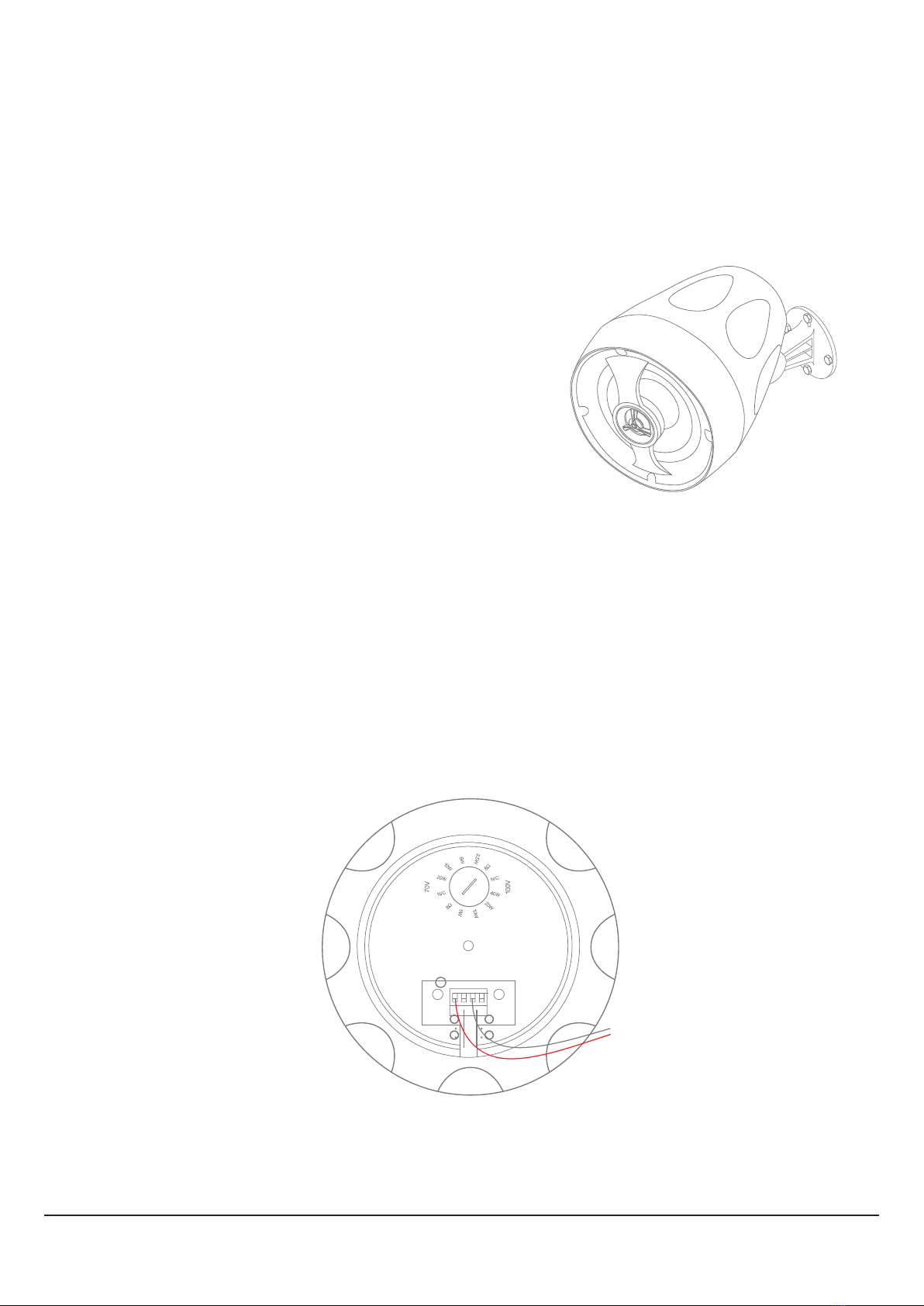
The MT-65 B/W speaker can operate in standard low impedance mode as well as in 100V/70V distributed
lines. The MT-65 B/W has a selector switch on the rear for selecting the mode of operations. The direction of the cut,
on the switch, is used to determine which mode of operation and/or power tap the speaker should be working
with. In this case the MT-65 B/W is configured to work as an 8Ω unit. Also, close to the selector switch is the
terminal block connector.
The MT-65 B/W offers versatility and performance,perfect
for both residential and commercial audio applications, the
MT-65 B/W provides a wide listening field with exceptional sound
quality. Optimized design using a 6.5" polypropylene cone woofer
that provides deep clear bass paired-up with a 1" silk dome tweeter
that produces balanced, lifelike tone and musical reproduction.
The IP66 rated weather and dust resistant enclosure is finished
with an eye-pleasing matte texture that fits perfectly into any home
or commercial setting.
PAGE 3

LOW IMPEDANCE
The MT-65 B/W in the low impedance mode of operation has a nominal impedance of 8Ω. If there is the need
to connect multiple speakers in parallel, be sure to follow the amplifier’s specifications in relation to the minimum
allowed impedance. Most amplifiers allow for a minimum 4Ω impedance which corresponds to two MT-65 B/W
speakers connected in parallel.
100V DISTRIBUTED LINES
The MT-65 B/W comes standard with a transformer for 100V/70V distributed lines, to use your speaker in the
100V distributed line mode, use the selector to configure the desired power tap (5W, 10W, 20W, 40W) for 100V and
(2.5W, 5W, 10W, 20W) for 100V.
AMPLIFIER
100V - 10W 100V - 5W 100V - 20W
100V AMPLIFIER
PAGE 4

100V LINE INSTALL REQUIREMENTS
100V POWER AMPLIFIER REQUIREMENTS
Make sure you have a powerful enough amplifier for your setup of MT-65 B/W loudspeakers. It must have at
least the total sum of power values chosen on your P6 as power tap. Applying the 20% headroom rule, in this
case, is the ideal scenario. Considering the example above, for 100V, you will need at least (10+5+20) x 1.2 = 42W
of amplifier power.
INSTALLATION
GENERAL CONSIDERATIONS
The VL Auido MT-65 B/W can be either suspended in a pendant configuration, mounted on a wall or ceiling,
using the adjustable wall-mount stand and used in a garden. Prior to installing, check the chosen structure for
weight bearing capability.
PAGE 5

HANDS-ON
SUSPENSION INSTRUCTIONS
Route the cables through the top cover.
1.
In the MT-65 B/W, use the selector to choose your desired mode of operation and power tap. Strip the wires
about 3 to 4 millimeters from the tip and mount the supplied connector. Insert the connector on the MT-65 B/W
and after fixing the buckle part, fit the cover in the MT-65 B/W and with the supplied eye bolt and nut. Be sure to
check that the eye bolt is properly and sufficiently inserted as it is through it that the MT-65 B/W is suspended.
Route the hanging cable through the eyebolt and using the two supplied carabiners secure the MT-65 B/W
to the structure. NOTE: For faster and easier installation use the available Gripple accessories.
2.
3.
CEILING
POLE
HOOK
HANGING CABLE
CARABINER
PENDANT SPEAKER
Make sure the speaker is properly secured to the structure,
and the structure can handle the total weight suspended on
it. Failure to do so may cause damage or injuries.
WARNING
PAGE 6

WALL MOUNT INSTRUCTIONS
Unscrew the rotation center screw to separate
the plastic parts of the stand. Take care to not lose
any small parts.
1.
Mount the speaker part of the stand on the
MT-65 B/W. Connect the wires and screw the
top cover supplied with the wall mount.
3.
Reassemble the stand with the MT-65 B/W
already attached and adjust as required.
4.
Use the wall mount to mark the spots for the
holes. Keep in mind that the adjustable stand cannot
tilt the MT-65 B/W, it can only rotate up and down.
Secure the wall mount to the wall with four screws.
2.
Can’t rotate this axis after install
A
B
A
B
NOTE: The logo badge can be removed,
from the grille, without damage.
PAGE 7

TECHNICAL SPECIFICATIONS
PRODUCT TYPE FULL-RANGE PENDANT SPEAKER (8Ω/100V)
FREQUENCY RESPONSE (-6dB) 90Hz - 20Hz
NOMINAL COVERAGE 90° CONICAL
RMS POWER 40W
PROGRAM POWER 80W (8Ω)
NOMINAL IMPEDANCE 8Ω
SENSITIVITY (1W, 1m) 85dB
MAXIMUM SPL (CALCULATED) 104dB
TRANSFORMER TAPS 100V 5W, 10W, 20W, 40W
TRANSFORMER TAPS 70V 2.5W, 5W, 10W, 20W
LF DRIVER 6.5” POLYPROPYLENE CONE WOOFER
HF DRIVER 1” SILK DOME TWEETER
INPUT CONNECTORS PHOENIX TYPE PLUGGABLE TERMINAL BLOCK
CABINET MATERIAL HIGH-GRADE RUGGED POLYPROPYLENE
IP RATING IP66 (ONLY WITH REAR COVER IN PLACE)
DIMENSIONS (WxHxD) 208x280x208mm (8.19x11x8.19”)
NET WEIGHT 3Kg(6.61Lb)
SHIPPING WEIGHT 4Kg (8.82Lb)
PAGE 8

WWW.VL.CO.TH
DELIVERED THE ORIGINAL SOUND
Other manuals for MT-65 B
1
This manual suits for next models
1
Other VL Audio Speakers manuals


