Vlsi HEADSPEAKER - 5.1 User manual

HeaDSPeaker - 5.1 DSP Headphone
System With Head Tracking
USER'S ANUAL
Revision history
Rev. Date Author Chapters Description
01.11 24.03.09 L All Translated version

HEADSPEAKER – 5.1 HEADPHONE SYSTEM
Part # Photo Description Checked
1 DSP unit
2Head tracking sensor
(for headphones)
3
SB cable,
A plug
mini SB (5PIN) M
4230V – SB
adapter
53.5 mm 3.5 mm
audio cable
6Software installation
media
7 Volume attenuator
83.5 mm 2 x RCA
audio cable
Page 2

HEADSPEAKER – 5.1 HEADPHONE SYSTEM
1. G eneral in stru ction s
HeaDSPeaker 5.1 headphone system makes realistic, immersive multichannel audio
playback possible using regular stereo headphones. The underlying technology is based
on modeling the human auditory mechanisms using advanced signal processing
algorithms and real-time head tracking.
To be able to produce a surround sound experience that satisfies even the most
demanding users, head tracking feature is a necessity. For this purpose, HeaDSPeaker
system provides tracking sensors that can be attached to virtually any regular
headphones.
The ”brains” of the system is a DSP unit, which acts as a transmitter for the tracking
sensors. DSP unit processes multichannel audio signal in such a way that the user
perceives sound directions as if the sound was actually played back using a set of
surround loudspeakers.
HeaDSPeaker supports lossless 5.1 (or 7.1) PCM-audio via SB-bus, or alternatively
surround-encoded multichannel audio via analog stereo connector.
Analog stereo audio will be decoded to multichannel format using DSPeaker's proprietary
DSP-logic -decoder. DSP-logic can decode the most commonly used multichannel
formats in a way suitable for headphone use. This way HeaDSPeaker supports sound
sources including surround-encoded TV-broadcasts and the latest gaming consoles
among others.
To enjoy surround sound at the maximum, it is recommended to take a couple of
minutes to configure the system based on personal qualities. HeaDSPeaker package
contains the required computer software for easy configuration and diagnostics. At the
moment, only Windows XP and Vista plattforms are supported. A Macintosh version is
under development.
Page 3

HEADSPEAKER – 5.1 HEADPHONE SYSTEM
Page 4
Figure 1: A recommended placement for the DSP unit is at the top of the display device
Figure 2: Using the spring clip

HEADSPEAKER – 5.1 HEADPHONE SYSTEM
2. D S P U nit' s Indi c ator s and C onne ction s
2.1 Front panel
1 A DIO indicator led
•OFF = no audio input
•GREEN = audio input present
2 TRACKER indicator led
•OFF = direct stereo audio (no processing)
•GREEN = head tracking functioning normally
•ORANGE = errors in tracking or tracking disabled. Head tracking is automatically
turned off when no audio is present for a while, when connected via SB.
•RED = static 5.1-auralization, head tracking disabled
3 PCM / ANALOG indicator led
•OFF = only stereo sound from SB is available
•GREEN = multichannel (5.1 tai 7.1) audio available from SB
•ORANGE = analog input is active. DSP-logic decodes surround-encoded audio to 5
channels.
4 Head tracker ultrasound-transmitter
•Must be within ”line-of-sight” with sensors attached to headphones
Page 5
Figure 3: front panel indicators of the DSP unit
1
2
3
4
5

HEADSPEAKER – 5.1 HEADPHONE SYSTEM
5 Microphone for voice
•Only operates during SB connection
•Can be used, for example, in online-gaming
2.2 Re ar Pan el C onne ctor s
•LINE IN: Stereo (stereo encoded surround) line input, 3.5mm jack
•SB: digital multichannel audio input / set-up using a computer
•SENSOR: head tracking sensor connector, 3.5mm jack
•HEADPHONES: headphone output connector (binaural 5.1-audio), 3.5mm jack
2.3 C onne ctin g for U S B audio and S et up
•Attach the head tracking sensors (part #2) to your headphones using the provided strip
or other suitable way. Make sure that connection is secure and sensors are firmly in
place (see figure 5). Please note that orientation is significant, sensors must face
towards the DSP unit and have a clear line-of-sight.
•Attach signal cable (part #5) between head tracking sensor's connector and DSP-unit's
”sensor” connector.
•Attach headphone's signal cable to DSP-unit's “headphones” connector (figure 6).
•Attach SB-cable (part #3) between a computer and the DSP-unit.
•Insert installation media into computer's drive and proceed with software installation
(see chapter 3. for further information).
•Perform the set-up procedure using the diagnostic application as described in chapter 4.
Page 6
Figure 4: rear panel connectors of the DSP unit

HEADSPEAKER – 5.1 HEADPHONE SYSTEM
Page 7
Figure : tracking sensors securely attached to headphones
Figure 6: connections in USB-audio mode

HEADSPEAKER – 5.1 HEADPHONE SYSTEM
2.4 C onne ctin g for 5.0 D olby s urround
•Attach the head tracking sensors (part #2) to your headphones using the provided strip
or other suitable way. Make sure that connection is secure and sensors are firmly in
place (see figure 5). Please note that orientation is significant, sensors must face
towards the DSP unit and have a clear line-of-sight.
•Attach signal cable (part #5) between head tracking sensor's connector and DSP unit's
”sensor” connector.
•Attach headphone's signal cable to DSP unit's “headphones” connector (figure 6).
•Attach SB voltage adapter (part #4) between a mains output and DSP unit's SB
connector.
•Attach “line-in” to headphone output or line output of the signal source (TV, Xbox360,
Playstation 3 etc) using appropriate cable (part #8 or other suitable cable). Volume
attenuator (part #7) can be used between headphone output and the headphones.
Note 1: Please do not attach volume attenuator in the sensor-connector!
Note 2: If headphone output is used, please make sure that sound source doesn't do
any unnecessary signal processing. That can potentially prevent DSP-logic from decoding
from stereo to multichannel, or interfere with HeaDSPeaker's dynamic auralization.
Page 8
Figure 7: connections in Dolby surround mode

HEADSPEAKER – 5.1 HEADPHONE SYSTEM
3. S oft w are In stallation
Connecting the DSP unit to a computer's SB port will initiate the installation of required
system drivers. To make personal adjustments, it is highly recommended to install the
provided diagnostic software also.
To install the diagnostic software, place the provided installation disc in the disc drive.
Installation procedure should start automatically. If it doesn't, autorun feature is
disabled in the operating system. In this case, view the contents of the installation disc
in file browser and launch the installer program manually.
Installer program will start by presenting a list of optional components to install. It is
advisable to make a full install. Next, the program allows to define a destination
directory. When you're ready, click install to finish the installation.
3.1 S o und S etting s U nder Windo w s X P
After the software installation has completed, attach the DSP unit to a vacant SB port.
System should automatically identify the device and install any necessary hardware
drivers. After that, please make sure that HeaDSPeaker has the default sound device
status.
•Launch control panel from the Start menu.
•Open sound devices. A window similar to that shown in figure 8 should pop up.
Page 9

HEADSPEAKER – 5.1 HEADPHONE SYSTEM
•If the topmost line displays any other device than HeaDSPeaker, open up Audio tab.
Select HeaDSPeaker from the topmost drop-down list (see figure 9). This way sound
output from the computer goes through HeaDSPeaker whenever possible.
Page 10
Figure 8: Windows XP sound and audio properties

HEADSPEAKER – 5.1 HEADPHONE SYSTEM
•Return to the first tab (Volume) and click Advanced button. Channel configuration
dialog appears. Speaker setup should be in multichannel state. If it isn't, select 5.1
surround from the list as shown in figure 10.
•Close the window by clicking OK.
•Make sure that the device is working properly by launching the diagnostic software (see
chapter 4. for further information).
Page 11
Figure 9: selecting the default sound device

HEADSPEAKER – 5.1 HEADPHONE SYSTEM
3.2 S o und S etting s U nder Windo w s Vi sta
As above, connect the DSP unit to a vacant SB port. System should automatically
identify the device and install any necessary hardware drivers. After that, please make
sure that HeaDSPeaker has the default sound device status.
•Launch control panel from the Start-menu and select sound devices. A window similar
to that shown in figure 11 should pop up.
Page 12
Figure 10: selecting surround speaker setup

HEADSPEAKER – 5.1 HEADPHONE SYSTEM
•This list displays sound devices installed in the system. Please make sure that
HeaDSPeaker is present and has a green symbol indicating the default device status.
•If HeaDSPeaker isn't the default device, right-click it and select set as default device.
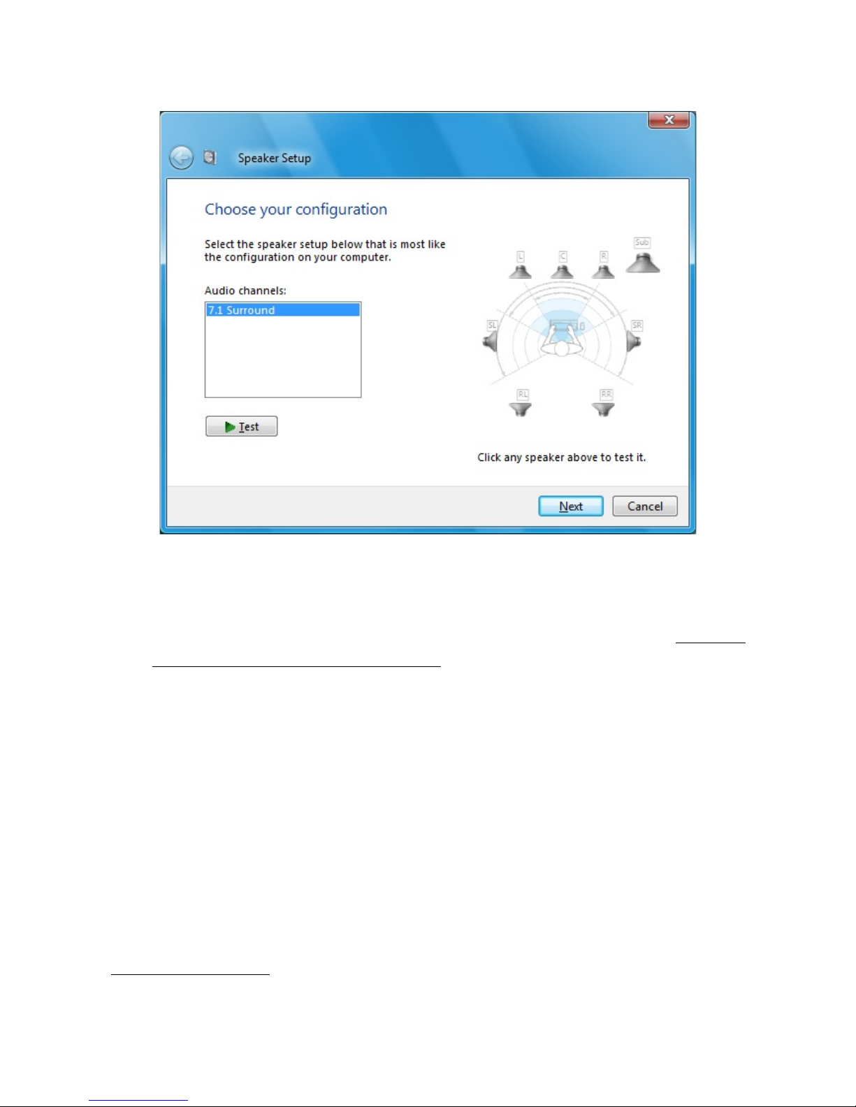
•Click the configure button at the bottom left to open a speaker configuration dialog
(figure 12). If multichannel audio configuration isn't activated, activate it from the list.
•Click next until configuration is finished. Now you're ready to launch the diagnostic
software as described in chapter 4.
Page 13
Figure 11: Sound and audio devices under Windows Vista
HEADSPEAKER – 5.1 HEADPHONE SYSTEM
3.3 Ch annel C onfiguration: 5.1 or 7.1 ?
HeaDSPeaker supports both 6-channel (5.1) and 8-channel (7.1) PCM-audio1, depending
on which firmware is installed in the device. If the name of the device has a postfix 8ch,
7.1 configuration is in use. Otherwise, six channel configuration is used. Which of the
configurations is a better choice in practise, depends on your operating system and other
applications.
Six-channel audio sources are considerably more widespread, so in general it is usually a
safer choice to use a six-channel firmware.
However, Windows Vista tends to matrix 5.1 audio channels in a way that may result in
impaired rear channel imaging. That's why we suggest 8-channel firmware for Vista
users, even if the intention is to use only 6-channel audio sources. In this case it is
advisable to use the diagnostic software to check application's behavior regarding audio
channel mapping (in particular, that rear channels are truly in the back, not in the sides).
1) when connected in SB-audio mode.
Page 14
Figure 12: Selecting surround sound setup

HEADSPEAKER – 5.1 HEADPHONE SYSTEM
Windows XP usually doesn't interfere with channel mapping, thus 6 channel mode is a
better starting point for 5.1 audio. Naturally, when full 8-channel audio is available,
corresponding 8-channel firmware should be installed regardless of the operating
system.
See page 22 for instructions on how to install the firmware.
Page 15

HEADSPEAKER – 5.1 HEADPHONE SYSTEM
4. Di a gno sti c A pplication
4.1 G en eral
Diagnostic application is a handy tool for making sure that settings are correct and the
device is working proprely. It allows adjusting several parameters according to personal
preferences. It is recommended that every user should choose an ear model that best
corresponds with individual directional hearing.
Start diagnostic application by clicking its shortcut in the desktop or start-menu folder.
Page 16
Figure 13: main screen of the diagnostic application
anage user
profiles
Open configuration
dialog
Firmware version
Head tracking
direction indicator
Change test
sound
inimize to 'notification
area' instead of taskbar
Close the
program
Add new profile

HEADSPEAKER – 5.1 HEADPHONE SYSTEM
You can hear directional test sounds by clicking any of the 7 virtual speaker icons
(subwoofer doesn't have a test sound so it cannot be clicked). Same speaker icons also
indicate channel activity. Thus, diagnostic application can be used to determine which
channels are used for audio in other applications.
Notice: if sounds are not played through the headphones, but merely through some
other device in the system (such as computer's internal speaker), check cabling and
status of the default sound device, as described in chapters 3.1 and 3.2 .
Indicator line at the bottom of the window represents tracked head direction. If tracking
sensors are correctly set-up, the line should reflect head movement. If the angle is not
straight up when your head is directly facing the display, adjust tracker offset to
compensate the angle difference. Tracker offset is one of the adjustable parameters
found in the settings screen.
Most of the settings are stored on a per-user basis. ser profile management allows
adding new users, all of which can have individual settings. You can switch active user
quickly without the need to manually re-configure the device every time.
Page 17

HEADSPEAKER – 5.1 HEADPHONE SYSTEM
4.2 M a kin g Per s on al A djust m ent s
When you're ready to make personal adjustments, click User Profile icon and select
Create New Profile (see figure 13). Type a name for the new profile and click Done. If
there is only a single person using the device, you can skip the previous step and modify
the default user directly.
Click the Config icon to open the settings dialog (shown in figure 14). It allows changing
the active ear model (which is used in producing the directional hearing sensation),
increasing or reducing head tracking sensitivity and adjusting the amount of spatial
processing (room response). You can also disable HeaDSPeaker's processing entirely.
Page 18
Figure 14: settings window
Adjust head tracker sensitivity
Adjust room response
Adjust tracker angle offset
Toggle between basic ear
models. Currently active
model is displayed in red.
Access complete
ear model database
Disable all processing
(enter bypass mode)
Disable head
tracking feature
Click any loudspeaker icon
to hear directional test sound

HEADSPEAKER – 5.1 HEADPHONE SYSTEM
Head tracker sensitivity adjusts the magnitude of the effect of the tracked head
movement. The easiest way to find the correct value is to play a test tone from any
channel. Rotate your head and pay attention on how the virtual sound source behaves
spatially. If tracker sensitivity is too great, sound source seems to travel to the opposing
direction when your head rotates. Conversely, too small value makes sound source to
”fall behind”. When the value is correct, sound source seems to stay in place.
HeaDSPeaker system supports a sophisticated room rendering algorithm. This setting
affects the acoustic reflectivity properties of a ”virtual auditorium”. If the value is set to
the minimum, rendering algorithm is disabled and only auralization (HRTF-based
processing) is performed. However, modelling the spatial properties of a virtual
auditorium improves the distance and externalization (out of head perception) of audio
sources.
Room response setting depends heavily on personal preference. It is also affected by
how much multichannel spatial cues the audio material itself contains.
Tip: if you need a quick way to toggle HeaDSPeaker's processing on and off (for
example, to listen to stereo music without processing): create a new user profile with
the profile manager, set bypass mode active to that profile only. You can now switch off
all processing with two mouse clicks, simply by activating that profile (as described later
in this manual).
Page 19

HEADSPEAKER – 5.1 HEADPHONE SYSTEM
4.3 Ch oo sin g an E ar M o del
Settings-window offers three most common ear models. The chosen model has a great
impact on the quality of the perceived directional sound. For best results, experiment
with the complete ear model database. The complete database is accessible by clicking
the advanced button.
You can activate an ear model simply by clicking its icon. Models are divided into five
classes (categories) named A, B, C, D and E. Within a class, differences between the
models are smaller. Select a different class from the list on the right to access all of the
models.
When evaluating a model, take advantage of test sounds in different directions. To play a
sound, click any of the speaker icons. The best model is the one that produces the best
immersion of directional audio in all directions. Please note that differences in the
models may cause some of them sound more ”colored” while others sound more natural.
It is normal that some of them may appear to be higher in the horizontal axis.
Page 20
Figure 1 : Choosing ear model from the complete database
Ear models are divided
into five classes (groups)
Activate ear models
by left-clicking icons
Click “Done” when you are satisfied
with selected ear model
Suitable alternatives can be
“highlighted” with right mouse button
This manual suits for next models
1
Table of contents
Other Vlsi Headphones manuals


