VLTG LX-300 User manual

Beam Moving Head Light
LX-300
User Manual
(RDM、Color LRD Display、Touch Operation)
Please read the user manual carefully before using

Contents
Chapter 1 Precautions and Installation ........................................................................................................1
1. Maintenance .......................................................................................................................................1
2. Statement ............................................................................................................................................1
3. Product Precautions.........................................................................................................................1
4. Lighting Installation..........................................................................................................................2
Chapter 2 Panel Operation ..............................................................................................................................3
1. Overview ..............................................................................................................................................3
2. Menu Operation................................................................................................................................3
1. Select Menu Item.....................................................................................................................3
2. Parameter Value Input ...........................................................................................................3
3. Setting Boolean Parameters.................................................................................................4
4. Subpage (Parameters).........................................................................................................4
3. Function Menu Description ...........................................................................................................5
1. DMX Address Code Settings................................................................................................5
2. Working Mode Settings..........................................................................................................5
3. Panel Display Settings ............................................................................................................6
4. Scene Mode...............................................................................................................................7
5. Parameters Settings ................................................................................................................7
6. View Fixture Status of Lighting............................................................................................8
Chapter 3 Channel Description.................................................................................................................... 10
1. Channel Table.................................................................................................................................. 10
Chapter 4 Common Failures and Cautions.............................................................................................. 13
1. Common Troubleshooting ......................................................................................................... 13
2. Precautions for Use ....................................................................................................................... 14
3. RDM Precautions for Use ............................................................................................................ 14

灯具使用说明书
第1页
Chapter 1 Precautions and Installation
1. Maintenance
This lamp should be kept dry to avoid working in a humid environment.
Intermittent use will effectively extend the life of the lamp.
In order to obtain good ventilation and lighting effects, pay attention to cleaning the fan
and fan net and the lens frequently.
Do not wipe the lamp body with organic solvents such as alcohol to avoid damage.
2. Statement
Its performance is intact and its packaging is complete before this product is shipped
from the factory. All users should strictly observe the warnings and operating instructions
stated above. Any damage caused by misuse is not covered by our warranty. Distributors are
not responsible for failures and problems caused by ignoring the operation manual.
This manual is subject to technical changes without notice.
3. Product Precautions
To ensure the life of the product, do not place the product in a humid or
leaky place, and do not work in an environment where the temperature
exceeds 60 degrees.
Do not place this product where it is liable to become loose or vibration.
To avoid the danger of electric shock, it need professional people to repair this product.
When the lamp is used, the power supply voltage should not change more than ±10%.
If the voltage is too high, the life of the lamp will be shortened. If the voltage is too low,
the light color of the lamp will be affected.
After the power is cut off, it takes 20 minutes for the lamp to cool down sufficiently
before it can be used again.
To ensure the normal use of this product, please read this instruction carefully.
The DMX connection uses an RS-485 cable with shielded, 120ohm characteristic
impedance, 22-24 AWG and low capacitive reactance. The terminals must be connected
using 3 or 5 pin XLR male / female connectors. (Minimum 1/4 W).
Important notice: The wires must not touch each other or the metal case.

灯具使用说明书
第2页
Figure 1 Schematic diagram of DMX cable connection
4. Lighting Installation
The lamp can be placed horizontally, Oblique hanging and upside down hanging. Pay
attention to the installation method when Oblique hanging and upside down hanging.
As shown in Figure 2, before positioning the lamp, you must ensure the stability of the
installation site. When upside down installation, you must ensure that the lamp does not fall
on the support frame, and you need to use a safety rope to pass through the support frame
and the lamp handle to ensure safety and prevent the lamp from falling and sliding.
When the lamp is installed and debugged, no pedestrians are allowed to pass under it.
Regularly check whether the safety rope is worn and the hook screws are loose.
We will not bear any responsibility for all the consequences caused by the falling
of the lamp due to the unstable installation of the hanging.
Figure 2 Schematic diagram of upside down lamps

灯具使用说明书
第3页
Chapter 2 Panel Operation
1. Overview
The schematic diagram of the luminaire panel is shown in Figure 3. The title above
shows the name of the luminaire, and the status bar below shows the signal of the current
luminaire, the status of the lamp, and the fault (When there is no fault information, "ERR" is
displayed, otherwise "NOR" is displayed).
This fixture supports DMX / RDM protocol. When the fixture is searched by the RDM
host, the three letters “RDM”will appear on the panel, indicating that the fixtures are
enumerated normally.
The display and operation are similar to "Android operating system", and you can
operate by clicking the corresponding item with your fingertip or a blunt object.
Note: Do not tap the display with sharp object to prevent damage.
Figure 3 Schematic diagram of display panel
2. Menu Operation
1. Select Menu Item
The area on the left is the TFT display area and the touch area. Use your finger or blunt
surface hardware to click on the contents of the panel, and you can complete
parameters setting or viewing status and other operations.
The right area is the auxiliary input. If you do not use the touch function that comes with
TFT, you can use the auxiliary input to select the items you want to set or view and
complete the operation.
2. Parameter Value Input
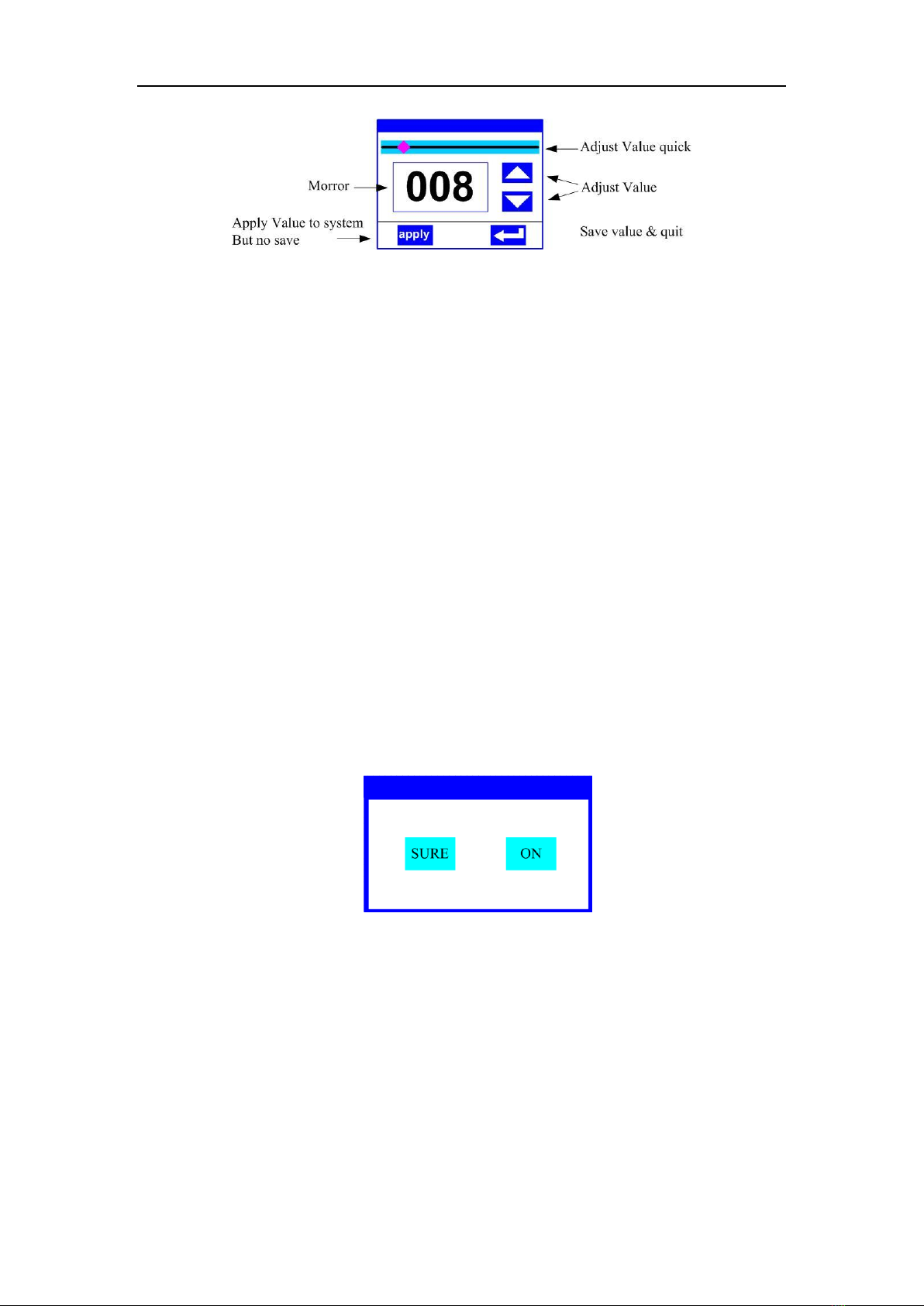
When the selected parameter item needs to enter a value, the window shown in Figure 4 will
open:
灯具使用说明书
第4页
Figure 4 Value setting page
Value Settings:You can directly pull the slider to set the required value quickly, or you
can click the right "Up" or "Down" button to set the required value precisely or use
auxiliary input to set it.
Apply Value:When the data is set by the "Up" or "Down" button, and the "Apply"
button in the lower left corner is pressed, the value is immediately sent to the fixture,
but the value is not saved.
Vale Save:Click the "OK" button in the lower right corner to save the current value to
the internal memory and apply the saved value to the fixture at the next boot.
3. Setting Boolean Parameters
When the parameter set is a Boolean value (such as ON or OFF), you can directly click
the corresponding item to switch the parameter value. This type of parameter will be
saved to the internal memory after modification. Press the parameter option on the
right, the corresponding option will be grayed out. When you release your hand, the
corresponding parameters will be changed and saved. If pressing the parameter option
is not the parameter you want to change, you can move your finger to another part of
the screen at this time, and the corresponding parameter will not change.
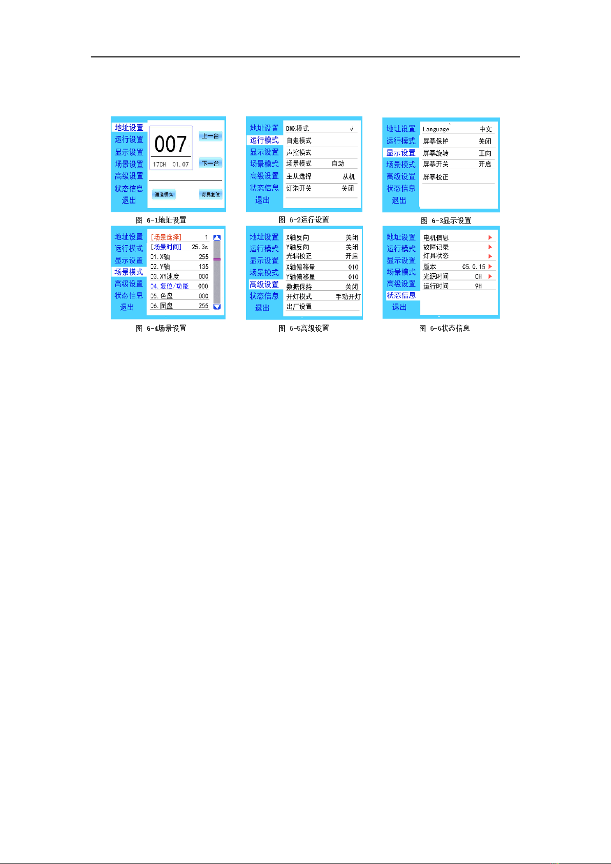
The determination of important Boolean parameters will be set through the
determination window, as shown in Figure 5 below:
Figure 5 Confirm input window
灯具使用说明书
第5页
4. Subpage (Parameters)
3. Function Menu Description
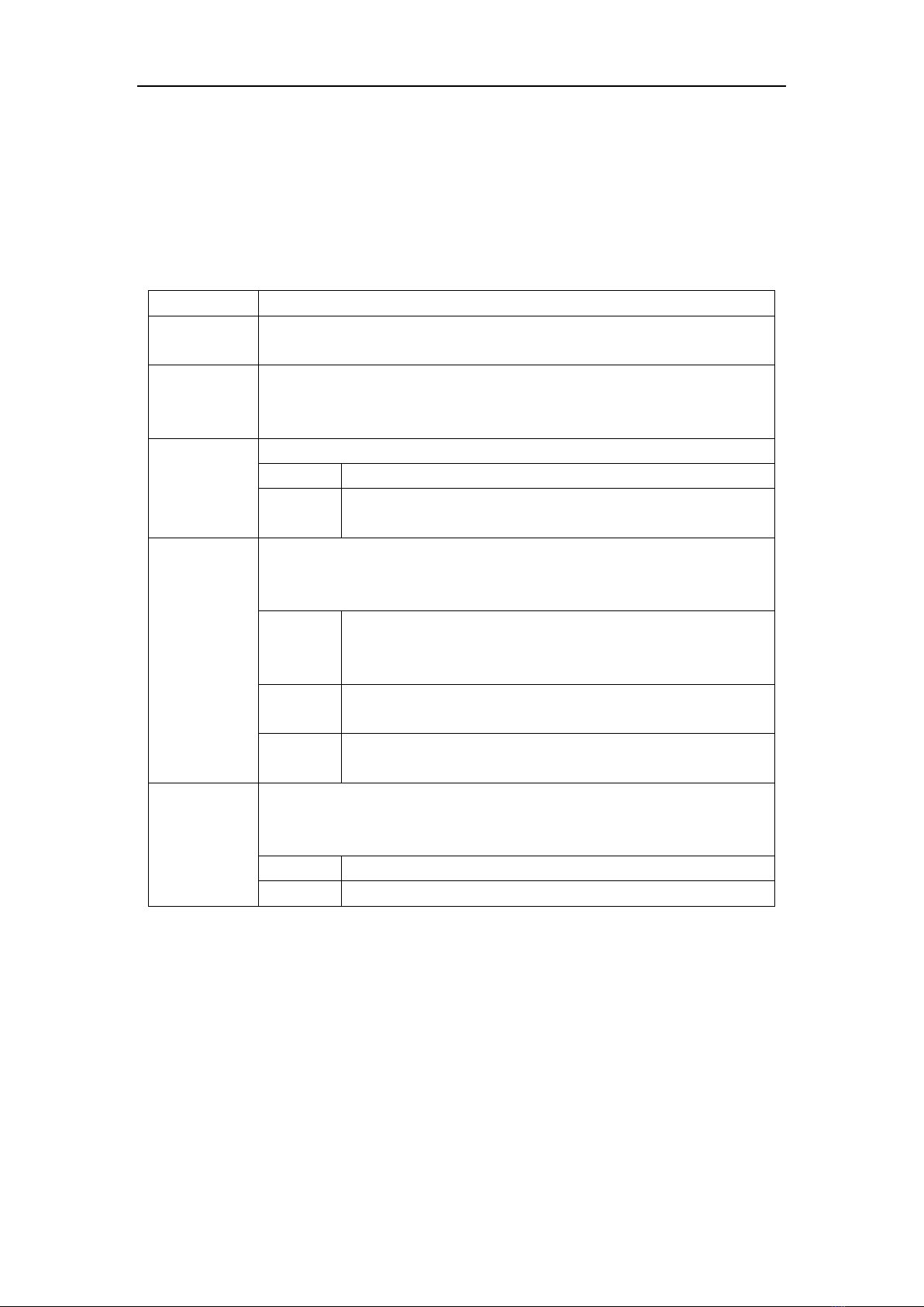
Enter the setting interface, as shown in Figure 6-1:
In the main interface, you can enter the corresponding parameter setting interface by
selecting six buttons.
In the parameter setting interface, you can press the blue option on the left to quickly
switch to other setting interfaces.
1. DMX Address Code Settings
You can set the DMX address and channel mode of the fixture through the page shown
in Figure 6-1.
The menu setting of the luminaire optimized the address setting. There are several
operations for setting the address code:
Select “Previous”or “Next”, the fixture will automatically calculate the address code of
the next or previous device based on the current address code and channel data, which
can be set quickly
Click the address code value to enter the value editing window. Here you can set any
valid address code. The luminaire automatically obtains the current channel number of
the luminaire and automatically filters the unusable address code (512-current channel
number
The lamp supports the RDM protocol, and the lamp address code can be set remotely
through RDM.
Two buttons are provided:
Channel mode: different channel modes can be selected cyclically;
Fixture reset: reset all motors.
灯具使用说明书
第6页
2. Working Mode Settings
The page shown in Figure 6-2 can be used to set the lamp's operating mode and control the
lamp. The luminaire supports four operating modes (DMX mode, self-propelled mode, sound
control mode and scene mode). For detailed parameter value settings, please refer to the
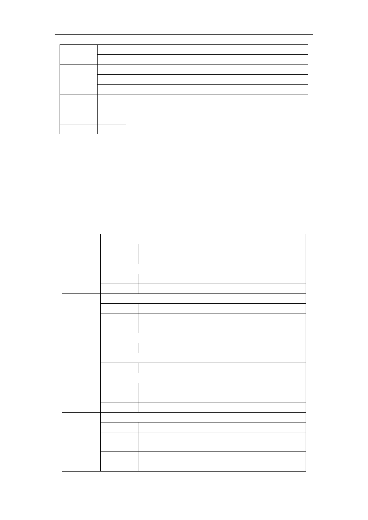
previous section. The specific parameter descriptions are shown in the following table:
Operating mode
DMX mode
Console mode, receive DMX signal, RDM signal
Self-propelle
d mode
Fixtures run automatically according to built-in program
Sound
control
mode
When the luminaire detects a strong sound, the luminaire automatically runs a
scene according to the built-in program, otherwise it keeps the last scene
Scene mode
01
Run in set scene mode, support custom editing of up to 10 scenes
1~10
Output the specified scene
Automatic
Automatically output scenes in the order of the set scene time
(non-zero). Scenes with time 0 are automatically skipped and ignored.
Self-propelle
d mode
When not in DMX mode, select the data output mode, the fixture automatically
detects the DMX status and automatically switches the output to prevent data
conflicts
Host
The lamps operate according to the built-in. If there is no signal from
DMX, data will be output (synchronized), otherwise no data will be
output.
Sub-host
Fixtures run as built-in, no data is output (other fixtures are not
synchronized)
Automatic
If there is no signal from DMX, the fixture will run as built-in;
otherwise, the fixture will work according to DMX
Light bulb
switch
(Bulb light source) Launch confirmation schedule, select "SURE" to confirm the
current operation, turn the lamp on or off, the switch interval is limited to 30
seconds
Close
Current lamp output is off
Open
Current lamp output is open
The scene mode is suitable for a single or a small number of fixtures. You only need to
output a fixed scene, or you need to run a simple program. You can edit the scene page
without connecting to the console.
If the light source is a light bulb, please wait 10 minutes after turning off the light bulb,
then turning on the light bulb.
3. Panel Display Settings
The lamp supports Chinese-English bilingual, upside down display, etc. Enter the corresponding
parameter settings as shown in Figure 6-3. The specific menu content is shown in the following
table:

灯具使用说明书
第7页
Display setting
Language
Set the display language
English
English display
Chinese
Chinese display
Screen
protector
Set the screen display content or mode after 30 seconds of no operation on the
screen
Close
Keep last operation page, on screen
Mode 1
Off screen
Mode 2
Black screen, showing the address code of the current fixture in the
lower left corner
Mode 3
Display trademark information, address code and operation mode
Screen
rotation
Set screen display orientation
Close
Do not reverse display
Open
reverse display
Automatic
Automatically detect the lamp hanging direction and automatically
switch the display direction
DMX
instructions
Set the DMX signal indicator
Mode 1
On when there is a signal, off when there is no signal
Mode 2
Off when there is a signal, on when there is no signal
Mode 3
Flashes when there is a signal, off when there is no signal
Signal
indication
brightness
Set the brightness of the signal indicator
1~10
10 levels
Screen
backlight
Set the brightness after 10's of the screen backlight in no operation. Full light during
operation
1~10
10 levels
Touch screen
switch
Select whether to disable the touch screen. When the screen is accidentally
damaged, you can disable the touch function and use auxiliary input to set the
fixture.
Touch
correction
When the screen touch is not accurate, you can enter the calibration page
For touch-enabled lamps, if a bad touch occurs, you can enter the calibration page to
recalibrate the touch accuracy of the touch screen. Under normal circumstances, please do
not enter this page. If the touch is broken, select Disable touch switch.
4. Scene Mode
Enter the page shown in Figure 6-4, the fixture enters the scene editing mode. In this
page, the fixture does not receive DMX console data, and the edited data is reflected to the
fixture immediately.
The content of the page depends on the currently selected channel, and the displayed
channel content and order are consistent with the fixture channel table. Through this page,
10 scenes can be edited, as shown in the following table:
Scene Mode
灯具使用说明书
第8页
Scene
selection
Select the current operation scenario
1~10
10 scene setting formats
场景时间
Set the retention time of the current scene in auto mode, unit is 0.1 second
0
The current scene does not participate in automatic scene output
1-255
0..1 to 25.5 seconds
1. X axis
0-255
Set the data of each channel. The display content and sequence
correspond to the channel table of the fixture.
……
0-255
……
0-255
N. Function
0-255
If the effective reset data is edited in the reset channel in the scene, the fixture will be
reset, but after reset, the corresponding reset channel value will be automatically cleared to
prevent multiple consecutive resets.
View this page to get the current channel table order of the fixture. For detailed channel
data, please refer to the detailed channel description.
5. Parameters Settings
Enter the page shown in Figure 6-5 to adjust the field parameters of the luminaire to
facilitate on-site installation of the luminaire, etc.
Advanced settings
X axis
reverse
X axis reverse settings
Close
Do not reverse
Open
reverse
Y axis
reverse
Set Y-axis rotation direction
Close
Do not reverse
Open
reverse
Optocoupler
correction
Set whether the fixture detects XY out of step and corrects it
Close
Uncorrected position after out of step
Open
Automatically correct position after out of step and record out of
step failure
X axis offset
Set the position of the zero point of the X axis of the fixture
4-150
Y axis offset
Set the position of the zero point of the Y axis of the fixture
4-48
Data
retention
Set the output status of the luminaire when there is no DMX signal
Close
No signal, the motor and light source return to the position and
state when reset is complete
Open
No signal, keep the last frame of DMX data output
Lighting
mode
Set the way to turn on the lamp for the first time after power on
lighting
Turn on the lamp when power on, reset the lamp after 30 seconds
Lighting
after reset
Reset the lamp 3 seconds after power on, turn on the lamp after
reset is completed
Manual
lighting
After resetting, manually turn on the lamp through the menu or
console
灯具使用说明书
第9页
Reset
A confirmation box pops up. After selecting "SURE", the lamp parameters return to
the factory settings.
When the power-on mode is selected, the lamp will wait for 30 seconds after the power
is turned on to allow the lamp to fully start. After the internal voltage is stable enough, the
reset procedure is started. If the on-site power capacity is stable, the power-on lighting
mode is recommended.
When the luminaire cannot correct the position, please first check whether the "optical
coupling correction" is turned off.
When the signal is unplugged, if the position of the luminaire is not output as expected,
please check the "Data Hold" setting first.
When setting the XY offset, after completing the setting, first control XY with the
maximum stroke to check that X Y will not hit the positioning rod or the housing after
setting.
6. View Fixture Status of Lighting
Enter the page shown in Figure 6-6, you can view the information and real-time status
of the luminaire to know the use status of the luminaire. If the luminaire needs to after sale,
please provide the status information displayed on this page as a basis for judgment, as
shown in the following table:
Status information
Motor
information
Display information status of all motors and signals in the light
Hall-calibrated
Not displayed, indicating that the motor is not Hall-calibrated,
0 indicates that the motor is away from the calibration position,
and 1 indicates that the motor is at the calibration position
Status
Display motor reset completion status
X axis
Display real-time position value of X-axis optocoupler
feedback
Y axis
Display real-time position value of Y-axis optocoupler feedback
Optocoupler
Display the level status of two signals of X, Y axis optocoupler,
binary
Fault / status
recording
Display the last 8 fault records during lamp reset and operation. The fault records
will not be saved after power failure. The current power-on cycle is valid
Fault data
Total number of faults detected after power-on
12::03
Power-on time when the fault occurred, Unit is minute
Hall fault
Corresponding motor does not detect a valid Hall signal when
the motor is reset
Hall short
Corresponding to the valid Hall signal detected when the
motor is reset
Optocoupler
failure
No valid optocoupler signal detected when the corresponding
motor is reset
Out of step
Corresponding motor out of step during operation
Impact
positioning rod
Impact positioning rod when the motor is reset

灯具使用说明书
第10 页
Bulb failure
Bulb accidentally extinguished
Sensor failure
The temperature sensor signal is abnormal
Fan failure
Main fan is not working properly
Lighting
status
Display key status data of current light for reference
Communicatio
n
0~100%, Communication quality of the data link inside the
luminaire
Error count
Total number of error frames detected after power-on,
cumulative
Light source
temperature
Display the current temperature of the light source, "---"
means no detection
Display board
temperature
Display the current temperature of the display board or the
surrounding ambient temperature
Sensor 1
temperature
Display the current motherboard temperature or the ambient
temperature of the motherboard installation location
Version
Information
Display the information and version of the current light, an important reference for
after-sales maintenance
device
The name of the light, the same as the equipment information
of RDM
model
Model of the lamp, same as the model information of RDM
display board
Display board fixed version and serial number
Motherboard 1
Fixed version and serial number of motherboard 1
Light source
time
Record the total accumulated elapsed time when the light source is turned on,
unit is minutes. The user manually clears it as a time reference for the regular
maintenance of the light source.
Light time
Record the total accumulated elapsed time for lighting which cannot be cleared.
Unit is minutes
Chapter 3 Channel Description
1. Channel Table
This lamp channel can be viewed in the scene mode. The channel mode is set in the
"Address Settings" page. The detailed data is shown in the following table:
Channel
Name
Value
Description
CH1
X axis
0-255
0-540°
CH2
Y axis
0-255
0-270°
CH3
X-axis
fine-tuning
0-255
0-2°
灯具使用说明书
第11 页
CH4
Y-axis
fine-tuning
0-255
0-1°
CH5
XY speed
0-255
From fast to slow
CH6
Fog
0-127
No
128-255
Insert fog
CH7
Strobe
0-3
Close light
4-103
Slow to fast pulse strobe
104-107
Open light
108-207
Slow to fast strobe
208-212
Open light
213-251
Slow to fast random strobe
252-255
Open light
CH8
Dimming
0-255
0-100% Dimming
CH9
Color
0-4
White
5-8
White + Color 1
9-12
Color1
13-16
Color1 + Color2
17-21
Color2
22-25
Color2 + Color3
26-29
Color3
30-33
Color3 + Color4
灯具使用说明书
第12 页
34-38
Color4
39-42
Color4 + Color5
43-46
Color5
47-50
Color5 + Color6
51-55
Color6
56-59
Color6 + Color7
60-63
Color7
64-67
Color7 + Color8
68-71
Color8
72-76
Color8 + Color9
77-80
Color9
81-84
Color9 + Color10
85-88
Color10
89-93
Color10 + Color11
94-97
Color11
98-101
Color11 + Color12
102-105
Color12
106-110
Color12 + Color13
111-114
Color13
115-118
Color13 + Color14
119-122
Color14
灯具使用说明书
第13 页
123-127
Color14 + White
128-191
Flowing from fast to slow
192-255
Reverse flow from slow to fast
CH10
Gobo
0-4
White
5-9
Gobo1
10-14
Gobo2
15-19
Gobo3
20-24
Gobo4
25-29
Gobo5
30-34
Gobo6
35-39
Gobo7
40-44
Gobo8
45-49
Gobo9
50-54
Gobo10
55-59
Gobo11
60-64
Gobo12
65-69
Gobo13
70-74
Gobo14
75-127
Flowing from fast to slow
128-130
Stop
131-185
Reverse flow from slow to fast
灯具使用说明书
第14 页
186-190
Slow to fast dithering pattern 1
191-195
Slow to fast dithering pattern2
196-200
Slow to fast dithering pattern3
201-205
Slow to fast dithering pattern4
206-210
Slow to fast dithering pattern5
211-215
Slow to fast dithering pattern6
216-220
Slow to fast dithering pattern7
221-225
Slow to fast dithering pattern8
226-230
Slow to fast dithering pattern9
231-235
Slow to fast dithering pattern10
236-240
Slow to fast dithering pattern11
241-245
Slow to fast dithering pattern12
246-250
Slow to fast dithering pattern13
251-255
Slow to fast dithering pattern14
CH11
prism1
0-127
Remove the prism
128-191
prism1
192-255
prism2
CH12
Prism 1
rotation
0-127
0-400°
128-187
Flowing from fast to slow
188-195
Stop
196-255
Reverse flow from slow to fast
灯具使用说明书
第15 页
CH13
prism2
0-127
Remove the prism
128-191
prism3
192-255
prism4
CH14
Prism 2
rotation
0-127
0-400°
128-187
Flowing from fast to slow
188-195
Stop
196-255
Reverse flow from slow to fast
CH15
Dimming
0-255
From far to near
CH16
Reset
100-105
Turn off the lamp for more than 5 seconds
200-205
Turn on the lamp for more than 5 seconds
210-215
Reset XY for more than 5 seconds
220-235
Reset effect motor for more than 5 seconds
240-255
Reset for more than 5 seconds
Chapter 4 Common Failures and Cautions
1. Common Troubleshooting
The lamp contains professional components such as microcomputer circuit boards,
high-voltage power supplies, etc. For your safety and product life, non-professionals
must not disassemble the lamp and related accessories without authorization.
1. Bulb does not light (except LED light source)
Possible cause: The lamp is not completely cooled, or the lamp has reached the end
of its life, the treatment is as follows:
Due to abnormal operation, the bulb is not completely cooled. The lamp body should

灯具使用说明书
第16 页
be allowed to cool for more than 10 minutes to fully restore the interior to the normal
state, and then turn on the power again;
Check whether the lamp has reached the end of its life and should be replaced with a
new one;
Check if the light bulb and lighter circuit are leaking, falling off or having poor contact;
Replace with a new ballast.
2. The beam become dim
Possible cause: The lamp has been used for a long time or the light path is not clean.
The treatment is as follows:
Check whether the lamp has reached the end of its life and should be replaced with a
new one;
Check whether the optical components or light bulbs are clean, and whether there is
dust on the light bulb optical components. The bulbs and various parts in the lamps
should be cleaned and maintained regularly.
3. The pattern is blurred
Check whether the value of the electronic focus channel is suitable for the current
projection distance.
4. The lamp works intermittently
Possible cause: The internal circuit enters the protection state, and the processing is as
follows:
Check whether the fan is running normally or is dirty, causing the internal temperature
of the lamp to rise;
Check whether the internal temperature control switch is closed;
Check whether the lamp has reached the end of its life and replace it with a new one.
5. After the lamp is reset normally, it will not be controlled by the console.
Possible cause: The signal line is faulty or the lighting parameter settings are abnormal,
and the processing is as follows:
Check the start address code and the connection condition of the DMX signal cable
(whether the signal cable cable is intact and the connection head is loose);
Add signal amplifier and 120 ohm termination resistor;;
6. Light does not start
Possible cause: The power cable is bad, and the treatment is as follows:
Check whether the fuse on the power input socket is blown and replace the fuse;
Poor line contact due to vibration during long-distance transportation of lamps
Check the input power, computer board and other plug-in devices
2. Precautions for Use
Check whether the local power supply meets the requirements of the rated voltage of

灯具使用说明书
第17 页
the product, and the leakage protector, overcurrent protector, etc. meet the
requirements of the load;
Do not use power cords with damaged insulation, and do not connect power cords to
other wires;
The lamp uses strong wind cooling, which is easy to accumulate dust. It must be cleaned
once a month, especially the cooling air vent, otherwise it will be blocked by the
accumulated dust, resulting in poor heat dissipation and abnormality of the lamp.
When installing the lamp, the fixing screws must be tightened with safety ropes, and
checked regularly;
When installing and positioning the lamp, keep the minimum distance between any
point on the surface of the lamp and any flammable and explosive materials at 10
meters and the distance from the irradiated object is 2.5 meters. Please do not install
the lamp directly on the surface of flammable substances;
The continuous working time of the lamp is not recommended to exceed 10 hours, and
the interval between continuous startup of the lamp should not be less than 10 minutes,
otherwise it will not trigger normally due to overheating protection of the lamp;
The closing time of the on-off valve should not exceed 5 minutes. If you need to close
the light for a long time, you should use the console (lamp control channel) to turn off
the lamp;
In order to ensure that multiple lights better comply with the scene effect, the light
should not always be in the current scene, that is, start the next scene action, it is best
not to exceed 3 minutes to ensure that multiple fixtures can run synchronously;
During use, if the lamp is abnormal, stop using the lamp in time to prevent other faults
from being induced.
2. RDM Precautions for Use
RDM is an extended version of the DMX512-A protocol. It is a Remote Device
Management protocol. The traditional DMX512 protocol communication is one-way
communication. The protocol is based on the RS-485 bus. RS-485 is a time-sharing
multipoint and half-duplex protocol. Only one port is allowed to be output by the host at the
same time, so pay attention to the following points when using RDM:
To use a console or host device that supports the RDM protocol host;
To use a two-way signal amplifier, the traditional unidirectional signal amplifier is not
applicable to the RDM protocol, because the RMD protocol requires feedback data, and
the use of a unidirectional amplifier will block the returned data, resulting in the failure
to search for the lamps;
All lamps must be set to DMX mode to ensure that there is only one host on the signal
line;
A 120 ohm impedance matching resistor must be inserted between terminals 2 and 3 of
the terminal plug. When the signal line is relatively long, reducing the signal reflection
will let a differential signal to be more stable, which is beneficial to the quality of
communication;
When lamps are under DMX control, but cannot be searched by RDM, first check the

灯具使用说明书
第18 页
signal amplifier, and then check whether there is a bad contact between the 2 and 3
wires of the signal cable.
Table of contents


