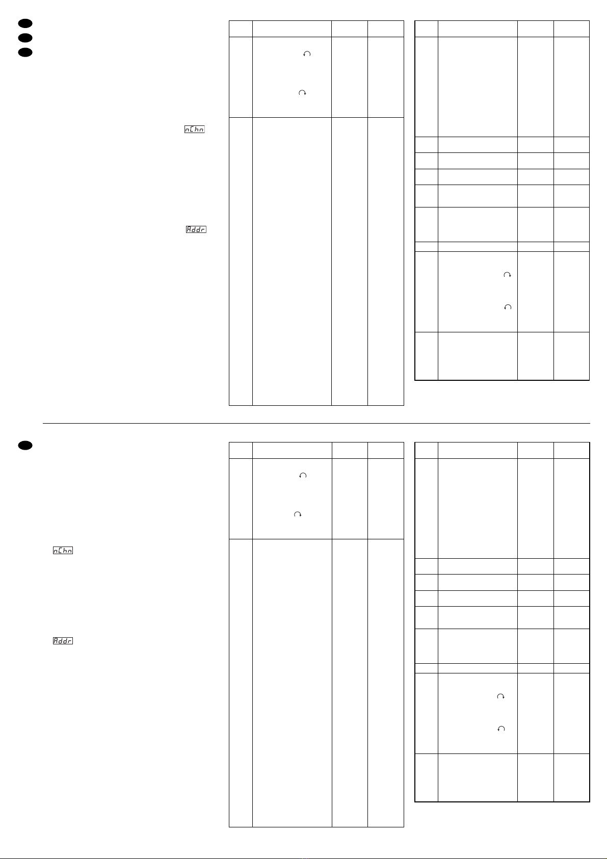
FHrS (Fixture Hours)
Durch Drücken der Taste MENU wird die Gesamtbe-
triebszeit des TWIST-250 angezeigt. Der Stunden-
zähler kann maximal 3000 Stunden zählen. Nach
Erreichen dieses Limits wechselt die Anzeige auf
gr3t (größer 3000h). Um den Zähler auf Null zu stel-
len, zuerst mit der Taste ENTER auf die Anzeige
FHrS zurückschalten. Dann gleichzeitig die Tasten
DOWN und UP drücken. Im Display erscheint Init
(Initialize). Bei Ausfall des Speichers wird FAIL an-
gezeigt. Durch Drücken der Taste MENU lässt sich
der nächste Menüpunkt anwählen.
nChn (Number of Channels)
Je nachdem welche Funktionen genutzen werden
sollen, kann die Steuerung des TWIST-250 über 10,
11 oder 13 DMX-Kanäle erfolgen:
10 Kanäle, wenn eine niedrige (8Bit) Auflösung der
Pan- und Tilt-Bewegungen ausreicht und die Funk-
tionen des Zusatzkanals (Beschleunigen/Bremsen*,
Reset, Lampe aus) nicht benötigt werden.
*Mit der Einstellung „langsames Beschleunigen und Bremsen“
wird ein sehr gleichmässiger Bewegungsablauf erreicht (z.B. bei
Fernsehlivesendungen oder Bühnenanwendungen) und mit der
Einstellung „schnelles Beschleunigen und Bremsen“ ein sehr
schneller Bewegungsablauf (z.B. für den Betrieb in Diskotheken).
11 Kanäle, wenn eine niedrige (8Bit) Auflösung der
Pan- und Tilt-Bewegungen ausreicht, aber die Funk-
tionen des Zusatzkanals benötigt werden.
13 Kanäle, wenn eine hohe (16Bit) Auflösung der
Pan- und Tilt-Bewegungen erforderlich ist und die
Funktionen des Zusatzkanals benötigt werden. Für
die Pan- und Tilt-Steuerung werden dabei je zwei
Kanäle belegt, einer für die Grob- und einer für die
Feineinstellung (siehe auch Kap. 6.4).
DieAnzahl der benötigten DMX-Kanäle (10, 11 oder
13) wird durch Drücken der Taste ENTER ange-
zeigt. Mit den Tasten UP und DOWN lässt sich die
Anzahl der Kanäle ändern. Die gewünschte Ände-
rung durch längeres Drücken der ENTER-Taste (bis
das Blinken endet) abspeichern. Eine noch nicht
abgespeicherte Änderung wird durch Drücken der
Taste MENU rückgängig gemacht.
dMMd (Dimmer Mode)
Der Dimmer-Modus wird durch Drücken der Taste
ENTER angezeigt. Mit den Tasten UP und DOWN
lässt sich die Einstellung ändern. Die gewünschte
Einstellung kann dann durch längeres Drücken der
ENTER-Taste (bis das Blinken endet) abgespeichert
werden. Mögliche Einstellungen:
CLOP (Close–Open) = dunkel →hell*
OPCL (Open–Close) = hell →dunkel*
*bei DMX-Werten 0–255, siehe auch Abb. 6 und 7
Eine noch nicht abgespeicherte Änderung wird durch
Drücken der Taste MENU rückgängig gemacht.
IPan (Pan Inversion)
Die Steuerungsrichtung des Dreharms wird durch
Drücken der Taste ENTER angezeigt. Mit den Tasten
UP und DOWN lässt sich die Einstellung ändern. Die
gewünschte Einstellung ist dann nach längerem Drü-
cken der ENTER-Taste (bis das Blinken endet) ab-
gespeichert. Folgende Einstellungen sind möglich:
no (normal) Pan normal
PI (Pan inversion) für eine entgegengesetzte Steue-
rung der Drehung (links und rechts drehend ver-
tauscht).
Eine noch nicht abgespeicherte Änderung wird durch
Drücken der Taste MENU rückgängig gemacht.
ItLt (Tilt Inversion)
Die Steuerungsrichtung des Schwenkkopfes wird
durch Drücken der Taste ENTER angezeigt. Mit den
Tasten UP und DOWN lässt sich die Einstellung
ändern. Die gewünschte Einstellung ist dann nach
längerem Drücken der ENTER-Taste (bis das Blin-
ken endet) abgespeichert. Folgende Einstellungen
sind möglich:
no (normal) Tilt normal
tI (Tilt inversion) für eine entgegengesetzte vertikale
Steuerung (nach oben und nach unten schwenkend
vertauscht).
Eine noch nicht abgespeicherte Änderung wird durch
Drücken der Taste MENU rückgängig gemacht.
teSt (Auto Test)
Um den Selbsttest zu starten, die Taste ENTER
gedrückt halten, bis t-On (test on) blinkt. Durch
Drücken der Taste MENU wird der Test beendet.
FLIP (Display Overturning)
Die Displayanzeige kann standardmäßig oder um
180° gedreht erfolgen (für abgehängte Montage).
Durch Drücken der ENTER-Taste werden beide
Möglichkeiten alternativ angezeigt. Die angewählte
Anzeigeart wird sofort abgespeichert. Durch Drü-
cken der MENU-Taste ist der nächste Menüpunkt
angewählt.
rSEt (Reset)
Zum Rücksetzen des Schwenkkopfes die ENTER-
Taste gedrückt halten, bis die blinkende Anzeige
r-On (reset on) erscheint. Der Schwenkkopf fährt
kurz in die Ausgangsstellung. Danach schaltet das
Gerät in den vorherigen Betriebsmodus zurück.
Addr (Address)
ZurAnzeige der DMX-Startadresse die Taste ENTER
drücken. Die Änderung der Startadresse erfolgt
durch die Tasten UP und DOWN. Nach dem Errei-
chen der gewünschten Adresse die Taste ENTER so
lange gedrückt halten, bis die Anzeige nicht mehr
blinkt. Das Blinken zeigt einen unterschiedlichen
Wert zum abgespeicherten Wert an. Eine noch nicht
abgespeicherte Änderung wird durch Drücken der
Taste MENU rückgängig gemacht.
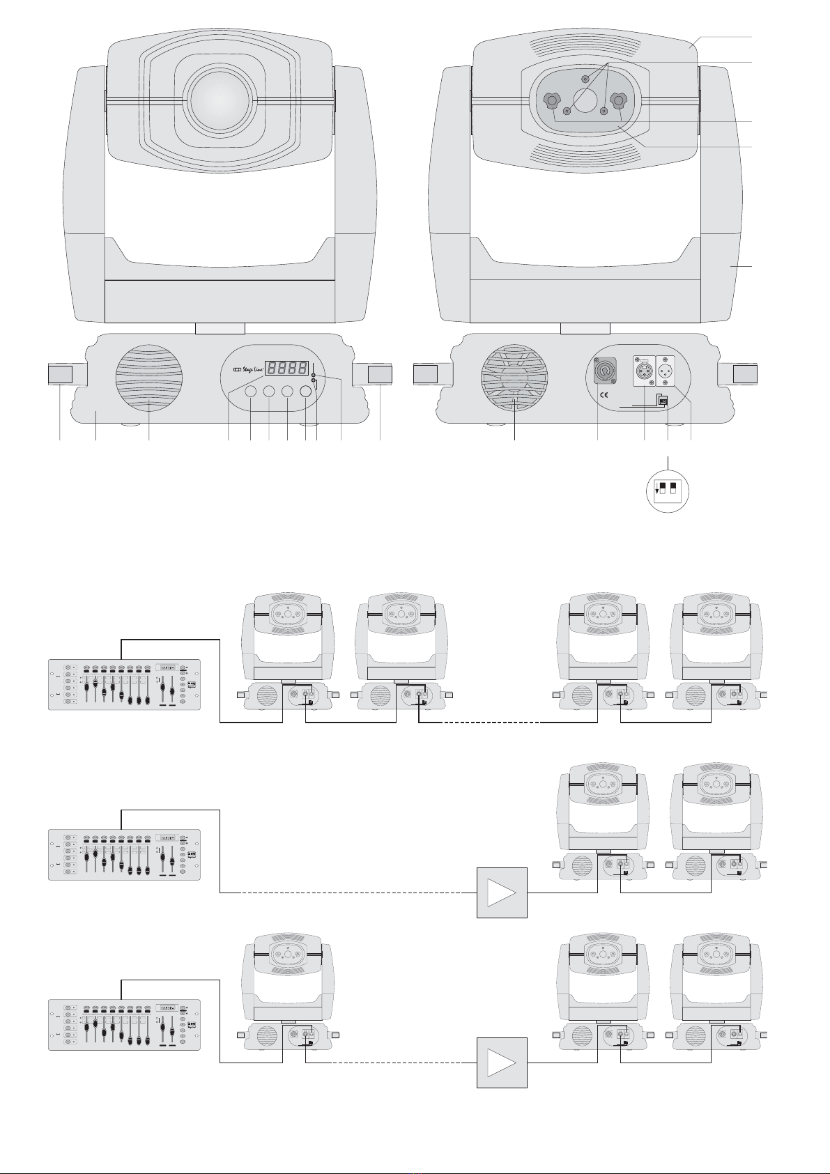
6.4 Steuerung des TWIST-250
Es besteht die Möglichkeit, eine niedrige (8Bit) oder
eine hohe (16Bit) Bewegungs-Auflösung für die
Pan/Tilt-Ansteuerung zu wählen. Im ersten Fall wer-
den 10 bzw. 11 DMX-Kanäle belegt, im zweiten Fall
13 DMX-Kanäle.
FHrS (Fixture Hours)
Press the button MENU to display the total operating
time of the TWIST-250. The hour counter can count
3,000 hours as a maximum. After reaching this limit,
the display changes to gr3t (greater than 3,000h).
To set the counter to zero, first switch back to the
display FHrS with the button ENTER. Then press
the buttons DOWN and UP at the same time. Init
(Initialize) is displayed. If the memory fails, FAIL is
displayed. Press the button MENU to select the next
menu item.
nChn (number of channels)
Depending on the functions to be used, the TWIST-
250 may be controlled via 10, 11, or 13 DMX chan-
nels:
10 channels if a low (8 bit) resolution of the panning
and tilting movements is sufficient and the functions
of the additional channel (accelerating/braking*,
reset, lamp off) are not required.
*Very even movements (e.g. for live TV programmes or stage
applications) are obtained with the adjustment “slow accelerating
and braking” and very fast movements (e.g. for disco applica-
tions) with the adjustment “fast accelerating and braking”.
11 channels if a low (8 bit) resolution of the panning
and tilting movements is sufficient but the functions
of the additional channel are required.
13 channels if a high (16 bit) resolution of the pan-
ning and tilting movements is necessary and the
functions of the additional channel are required. For
the control of panning and tilting two channels each
are reserved, one for the coarse adjustment and one
for the fine adjustment (also see chapter 6.4).
Press the button ENTER to display the number of
the required DMX channels (10, 11, or 13). The
number of the channels can be changed with the
buttons UP and DOWN. To memorize the desired
change, press the ENTER button for a longer time
(until the flashing stops). Press the button MENU to
cancel a change not yet memorized.
dMMD (dimmer mode)
To indicate the dimmer mode, press the button
ENTER. Change the adjustment with the buttons UP
and DOWN. To memorize the desired adjustment,
press the button ENTER for a longer time (until the
flashing stops). Possible adjustments:
CLOP (Close–Open) = dark →bright*
OPCL (Open–Close) = bright →dark*
*for DMX values 0–255, also see figs. 6 and 7
Press the button MENU to cancel a change not yet
memorized.
IPan (Pan Inversion)
Press the button ENTER to display the control direc-
tion of the rotary bracket. The adjustment can be
changed with the buttons UP and DOWN.To memo-
rize the desired adjustment, press the button
ENTER for a longer time (until the flashing stops).
The following adjustments are possible:
no (normal) pan normal
PI (pan inversion) for an opposite control of panning
(exchange of panning to the left and to the right).
Press the button MENU to cancel a change not yet
memorized.
ItLt (tilt inversion)
Press the button ENTER to display the control direc-
tion of the panning head. The adjustment can be
changed with the buttons UP and DOWN.To memo-
rize the desired adjustment, press the button
ENTER for a longer time (until the flashing stops).
The following adjustments are possible:
no (normal) normal tilt
tl (tilt inversion) for an opposite vertical control
(exchange of panning upwards and panning down-
wards).
Press the button MENU to cancel a change not yet
memorized.
teSt (self-test)
To start the self-test, keep the button ENTER pressed
until t-On (test on) flashes. Press the button MENU to
stop the test.
FLIP (display overturning)
The display can be indicated as a standard or turned
by 180° (for suspended mounting). Press the
ENTER button to display both possibilities alterna-
tively. The selected display type is immediately
memorized. Press the MENU button to select the
next menu item.
rSEt (Reset)
To reset the panning head, keep the ENTER button
pressed until the flashing display r-On (reset on)
appears. The panning head shortly goes to the start-
ing position. Then the unit switches back to the pre-
vious operating mode.
Addr (Address)
Press the button ENTER to display the DMX start
address. The start address is changed with the but-
tons UP and DOWN. After reaching the desired
address, keep the button ENTER pressed until the
display does not flash any more. The flashing shows
a value different from the memorized value. Press
the button MENU to cancel a change not yet memo-
rized.
6.4 Control of the TWIST-250
It is possible to select a low (8 bit) or a high (16 bit)
resolution of movement for the control of panning
and tilting. In the first case 10 or 11 DMX channels
are reserved, in the second case 13 DMX channels.
7
GB
D
A
CH