VMB TE-076 PRO User manual

VMB ESPAÑOLA S.A.
Pol. Ind. Picassent - Calle 2, final - 46220 Picassent (VALENCIA) Spain
Tel.: +34 902 34 10 34 - Fax: +34 961 22 11 77
6
TE-076
ETORRE ELEVADORA
MANUAL DE INSTRUCCIONES
ELEVATOR TOWER
GB OPERATING INSTRUCTIONS
DTRAVERSENLIFT
BEDIENUNGSANLEITUNG
FPIED ÉLÉVATEUR
MODE D'EMPLOI

Recycledpaper

NOTAS
Calidad / Seguridad - Qualität / Sicherheit
Qualité / Sécurité - Quality / Safety
Fabricante - Manufacturer - Hersteller - Fabricant
VMB Española S.A. Pol. Ind. Picassent - Calle 2, final - 46220 Picassent (VALENCIA) Spain - Tel.: 902 34 10 34 - Fax: 961 22 11 77

6
TE-076
Q
PH
S
T
BT
FJ
R
V
M2
M4
N2
W
N1
M4
M3
M1
BT
M2
MA
Posición
liberado
Posición
armado
LISTA DE PIEZAS
Ref.
2027 Gatillo retén patas.
2029 Pomo baquelita.
2030 Platillo apoyo estampado.
2037 TornilloM-8.
2040 TornilloM-6.
2046 Tuerca M-5.
2047 Arandela.
2048 Arandela.
2049 TornilloM-6.
2050 TornilloM-5.
2133 TornilloM-6.
2134 Perno roscado M-12.
2139 TornilloM-6.
2140 Tuerca.
2141 TornilloM-8.
2142 Pletina acero.
2143 Abrazadera acero.
2152 Arandela M-8.
2154 Pletina acero.
2155 Roldana acero.
2156 Pletina acero.
2157 Roldana acero.
2158 Tornillo M-12.
2159 Perno roscado M-16.
2160 Cabrestante.
2161 Manivela de acero estampado.
2162 Tornillo M-12.
2163 Roldana acero.
2164 Eje acero.
Ref.
2165 Roldana acero.
2166 Pletina acero.
2167 Eje acero.
2168 Roldana acero.
2169 Pletina acero.
2170 Pomo baquelita.
2171 Ruedas.
2172 Tramo base.
2173 Tramo 1.
2174 Tramo 2.
7603 Tramo 3.
7604 Tramo 4.
2176 Pata base.
2190 Cable acero.
2195 Estabilizador completo.
2193 Gatillos sistema ALS tramos 1, 2 y 3.
2194 Gatillos sistema ALS tramo 4 (corto).
7652 Bloqueo de transporte.
2193 Palomilla bloqueo de transporte.
7631 Pletina acero.
7632 Roldana acero.
7633 Pletina acero.

Manual de instrucciones ESPAÑOL
CONTENIDO
1. Introducción
2. Datos técnicos
3. Medidas de seguridad
4. Instrucciones de uso
5. Mantenimiento
1. Introducción.
Estimado cliente,
Para facilitar el manejo fiable de la torre
elevadora TE-076 PRO, hemos creado este
manual de instrucciones.
Leaatentamenteestemanualantesdeutilizar
la torre elevadora.
Observe los datos técnicos.
Nuestros productos han sido sometidos a
durísimas pruebas y controles durante el
proceso de fabricación.
Solamente deben utilizarse piezas de
repuesto originales.
El usuario pierde todos los derechos de
garantía, si incorpora otros repuestos que no
sean originales o lleva a cabo cualquier
modificación en el producto.
Para cualquier consulta sobre el producto,
debe indicarse el número de referencia y el
año de construcción o número de serie.
2. Datos técnicos.
2.1 - Torre elevadora modelo TE-076 PRO.
2.2 - Diseñada para levantar cargas en
sentido vertical a diferentes alturas, como
soporte de aparatos de iluminación.
2.3 - Carga máxima elevable : 200 Kg.
2.4 - Carga mínima elevable : 25 Kg.
2.5 - Altura máxima : 6,50 m.
2.6 - Altura mínima : 1,75 m.
2.7 - Superficie de la base : 2,47 x 2,47 m.
2.8 - Peso de transporte : 95 Kg.
2.9-Materialdeconstrucción:Perfildeacero
según DIN 2394.
2.10 - Sistema telescópico de 5 tramos
accionados por cable de acero guiado por
poleas acanaladas con cojinetes de
rodamiento a bolas.
2.11-Cabrestante:500Kg.decargamáxima
con freno automático de retención de la
carga.
HomologadoenDüsseldorfsegúnDIN15020
y VBG 8 con el nº 93 310.
2.12-Cable:AcerosegúnDIN3060.Calidad
180 Kg/mm2resistente a la torsión.
2.13 - Diámetro del cable : 6 mm.
2.14 - Fijación de los tramos de la torre a la
altura de trabajo por gatillos de seguridad
automáticos sistema Auto-Lock.
2.15 - Platillos estabilizadores ajustables en
las patas, con apoyos antideslizantes de
caucho.
2.16 - Anclaje de las patas por gatillos de
seguridad.
2.17-Niveldeburbujaparaajustarlaposición
vertical de la torre.
2.18 - Protección antióxido y acabado por
zincado electrolítico.
2.19 - Ruedas direccionables para el
transporte de la torre en posición vertical y
plegada hasta su emplazamiento de trabajo.
3. Medidas de seguridad.
3.1 - Colocar la torre elevadora sólo en
superficies duras y planas.
TE-076
D
D-2
2027
2027
D-1
D-3
7652 D-2
2193
2169
2165
2166
21332164
2133 2167
2168
7635
7635
7635
7635
7635
D-1
D-3 7634 7637
2133 7636
7635
BT

2159
2190
2160
2161
2050
2037
2029
2051
2047
2048
2162
B-1
B-1
BC
2163
2140
2051
2030
2046
2049
Estabilizador
completo.
Ref: 2195
TE-076
Manual de instrucciones ESPAÑOL
3.2 - Comprobar que las patas están
insertadas a fondo y sujetas por los gatillos
retenedores de seguridad (R).
3.3 - Comprobar que la torre se encuentra en
posición vertical mediante el nivel de burbuja
(F) situado en el tramo base. Ajustar si fuera
necesario con los platillos de apoyo (Q),
girandolamanivela(H)enelsentidoadecuado.
3.4 - Comprobar que la torre elevadora está
bloqueadaenlaposicióndetrabajomediante
los gatillos automáticos de seguridad (M1,
M2, M3, M4),girando lamanivela delcabres-
tante en sentido contrario a las agujas del
reloj. La torre deberá permanecer fijada a la
altura de trabajo. Una vez comprobado, girar
la manivela del cabrestante en el sentido de
las agujas del reloj hasta tensar el cable.
3.5 - Si se utiliza al aire libre, colocar la torre
ensuelofirmeyasegurarlacontralacargadel
viento mediante tirantes.
3.6 - No usar escaleras encima de la torre ni
apoyarlas en ella.
3.7 - Cuidado con salientes, cables, etc. por
encima de la torre.
3.8 - No ponerse debajo de la carga.
3.9 - No mover la torre si está con carga y
elevada.
3.10 - Antes de utilizar la torre, verificar el
estado del cable, éste no debe presentar
rotura de hilos o aplastamiento. No usar
nunca cables en malas condiciones.
3.11 - No desmontar nunca la manivela del
cabrestante (W) si la torre está con carga y
elevada.
3.12-Lacargamínimaparaunfuncionamiento
del freno sin problemas es de 25 Kg. Sin esta
carga mínima el freno no actuará.
3.13-Noengrasarnilubricarelmecanismode
freno del cabrestante.
3.14 - No autorizada para elevador de
personas.
3.15 - Para el transporte hay que bajar todos
los tramos y bloquearlos con el soporte BT.
4. Instrucciones de uso.
4.1 - Colocar la torre elevadora apoyada en
las ruedas direccionables de transporte (T)
sobre una superficie plana y firme en su
emplazamiento de trabajo.
4.2 - Sacar las patas (P) de su soporte para
transporte (S) e insertarlas a fondo en sus
alojamientosdetrabajo(V)comprobandoque
quedansujetasporlosgatillosretenedoresde
seguridad. (R)
4.3 - Ajustar la posición vertical de la torre
mediantelosplatillosdeapoyoregulables(Q)
girando las manivelas (H) en el sentido
necesario para lograr que la burbuja del
indicador de nivel (F) quede centrada en el
círculo.
4.4 - Soltar el soporte de transporte BT.
Colocar la carga a elevar sobre la torre
medianteunsoporteadecuadosegúnelcaso,
de forma que el peso de la carga sólo actúe
ensentido vertical.Lacargadeberásercomo
mínimo de 25 Kg. Esta quedará bloqueada
automáticamenteencualquierposiciónporel
sistema automático de seguridad Auto-Lock.
4.5 - Elevar:
Girarlamaniveladelcabrestante(W)en
el sentido de las agujas del reloj (N1),
elevandolacargahastalaposicióndeseada,
comprobando que los gatillos automáticos
van enclavándose, fijando automáticamente
los tramos.

2174
2134
2152 2152
2141 2140 2139
21552142
2154
2141 2140 2139
TE-076
2134
2048 2048
2142
2156
2157
A
2173
7603
2134
7632
7633
7631
2048 2048
2140
A-2
2172
7604
Gatillos
sistema
ALS
2141
A-3
A-2
2139
A-3
A-1
BT
A-1
Gatillo
tramo 4
Gatillos
tramos base,
1, 2 y 3
2191k2191
Manual de instrucciones ESPAÑOL
4.6 - Descenso:
Liberar el gatillo de seguridad (M1).
Para liberar los gatillos de seguridad, hay
que elevar ligeramente la carga con el
cabrestante para soltarlos. En la posición
normal de trabajo, el peso de la carga impide
liberar los gatillos. Una vez desbloqueado el
gatillodeseguridad(M1),girarlamaniveladel
cabrestante en sentido contrario a las agujas
del reloj (N2) hasta que, descendiendo la
carga, quede bajado al máximo el tramo 1.
Liberarelgatillo(M2)yseguirbajandolatorre
hasta que éste segundo tramo baje al
máximo. Liberar el gatillo (M3) y seguir ba-
jando la carga igualmente hasta que este
tramo quede bajado al máximo. Liberar el
gatillo (M4) y seguir bajando la carga hasta
que la torre quede completamente plegada a
su altura mínima.
La torre puede dejarse en cualquier
posición intermedia que se necesite del
mismo modo que al subir la carga.
4.7 - Para transportar la torre es necesario
plegarlabajandocompletamentelostramosy
fijarlos con el soporte de transporte BT.
Desmontar las patas liberando los gatillos de
retención y colocarlas en su posición de
transporte (S). Apretar los tornillos de
sujección (J).
5. Mantenimiento.
5.1- Comprobarperiódicamenteelestadodel
cable. Si un cable presenta rotura de hilos o
aplastamiento, debe ser sustituido
inmediatamente por otro nuevo. No utilizar
la torre elevadora con cables en mal estado.
Utilizar sólamente cable de acero DIN
3060 resistente a la torsión.
5.2 - La torre elevadora se suministra
completamente engrasada de fábrica. No
obstante, se recomienda engrasar
periódicamente según el uso, la corona
dentada del cabrestante, los cojinetes del
arbol de accionamiento y el buje, la rosca de
la manivela y los tramos.
ATENCION:
Noengrasarnilubricarelmecanismo
del freno.
Losdiscosdefreno,hansidoengrasados
conuna grasaespecialresistente alcalory la
presión. No deben ser utilizados otros
productosparaevitarinfluirnegativamenteen
el funcionamiento del freno.
No es necesario engrasar los discos de
freno.
5.3 - La torre elevadora TE-076 PRO, debe
sercomprobadaporunexpertocomomínimo
una vez al año de acuerdo con su utilización.
5.4 - Sólamente deben utilizarse piezas de
repuesto originales para garantizar una
continuada seguridad de uso.
El usuario pierde todos los derechos de
garantía, si incorpora otros repuestos que no
sean originales o lleva a cabo cualquier
modificación en el producto.
5.5 - Para solicitar cualquier pieza de
repuesto, debe indicarse su número de
referencia, que figura en las hojas de
despiece de este manual.
A-1

6
2176
C
TE-076
2170
2171
B
A
D
2026-C
2026-B
2026-B
2026-B
CERTIFICADO DE HOMOLOGACION DE LAS TORRES ELEVADORAS TE-076 PRO
Por la presente, VMB ESPAÑOLA, S.A.declaramos que las torres elevadoras para aparatos
de iluminación, modelo TE-076 PRO, responden a las prescripciones siguientes:
TIPO DE MAQUINA
MODELO
DESCRIPCION
NORMAS DE PRUEBA
RESULTADOS
Torre elevadora telescópica.
TE-076 PRO
Elevador telescópico de 5 tramos.
Altura mínima : 1.75 m.
Altura máxima : 6.50 m.
Peso mínimo de elevación : 25 Kg (250 N).
Peso máximo de elevación : 200 Kg (2.000 N)
Superficie base 2.47 x 2.47 m.
Cabrestante elevador de AL-KO.
VBG 70 (GUV 6.175) / GUV 66.15
La torre elevadora telescópica sirve para la elevación y soporte
vertical de cargas en espacios cerrados (empleando una fijación
conforme a las exigencias estáticas, también sirve para su
utilización en espacios al aire libre).
Con el peso elevado y los pasadores de seguridad insertados, la
torre elevadora cumple con las exigencias de la VBG 70 (GUV
6.15).
14. 03. 97. Ingeniero Olaf V. Brandt
La torre elevadora VMB modelo TE-076 PRO suministrada por VMB ESPAÑOLA, S.A. corresponde
a la muestra verificada.
Vicente Matali
Director Técnico
VMB ESPAÑOLA S.A.
Pol. Ind. Picassent - Calle 2, final - 46220 Picassent (VALENCIA) Spain
Tel.: +34 902 34 10 34 - Fax: +34 961 22 11 77

VMB ESPAÑOLA S.A.
Pol. Ind. Picassent - Calle 2, final - 46220 Picassent (VALENCIA) Spain
Tel.: +34 902 34 10 34 - Fax: +34 961 22 11 77
Operating instructions ENGLISH
CONTENTS
1. Introduction.
2. Technical information.
3. Safety precautions.
4. Operation.
5. Maintenance.
1. Introduction.
Dear customer,
In order to make a reliable operating of the
elevatortowerTE-076PROpossible,wehave
created this operating instruction.
Before use, you are required to read the
operating instructions.
Please note the technical data.
Our products are subjected to stringent test
prior to series production and are monitored
continously and closely during the
manufacturing process.
Inorder tomaintain thisguarantee offunction
andsafety,originalpartsofthemanufacturer's
design must be used. The user forfeits all
rights to claim if parts other than those of the
manufacturerareusedormodifiestheproduct
in any other way.
We reserve the right to modify design and
performance without prior notice when
contacting us with queries or ordering
spare parts the model type, year of manu-
facture, and serial number are to be
quoted.
2. Technical information.
2.1 - Elevator tower TE-076 PRO.
2.2 - Designed to lift loads vertically up to
different heights as support for sets of
illumination.
2.3 - Maximum load : 200 Kg.
2.4 - Minimum load : 25 Kg.
2.5 - Maximum height : 6,50 m.
2.6 - Minimum height : 1,75 m.
2.7 - Area of base : 2,47 x 2,47 m.
2.8 - Transport weight : 95 Kg.
2.9-Constructionmaterial:Steelprofiles DIN
2394.
2.10 - 5 profiles telescopic system operated
by cable of steel and guided by channelled
steel pulleys with ball bearings.
2.11 - Winch : 500 Kg. of maximum load with
automatic brake to stop the load.
Certificated in Düsseldorf according to DIN
15020 and VBG 8 with the number 93 310.
2.12-Cable:SteelDIN3060.Quality180Kg/
mm2. Twisting - resistant.
2.13 - Cable diameter : 6 mm.
2.14 - Fixing of the profiles to the height
desired by safety steel ST-37 catches.
2.15 - Adjustable stabilizing disc feet in the
legs with ruber non slip supports.
2.16 - Anchor of the legs by safety catches.
2.17-Spiritleveltoadjusttheverticallityofthe
tower.
2.18 - Antirust protection and electrolitic
cadmiated.
2.19 -Swivel wheels for the vertical transport
of the tower to its working location when
folded.
CERTIFICAT D’HOMOLOGATION DES PIEDS ÉLÉVATEURS TE-076 PRO
VMB ESPAÑOLA, S.A.certifies que les pieds élévateurs pour appareils d’illumination, modéle
TE-076 PRO, correspondent aux indications suivantes:
TYPE DE MACHINE
MODÉLE
DESCRIPTION
NORMES DES ESSAIS
RESULTATS
Tour élévatrice télescópique.
TE-076 PRO
Elévateur téléscopique de 5 tronçons.
Hauteur min. : 1.75 m.
Hauteur max. : 6.50 m.
Charge min. : 25 Kg (250 N).
Charge max. : 200 Kg (2.000 N)
Surface base 2.47 x 2.47 m.
Cabestant élévateur AL-KO.
VBG 70 (GUV 6.175) / GUV 66.15
La tour élévatrice télescopique, employant une fixation conforme
aux exigences statiques, sert á l’élévation et au support vertical des
charges aussi bien en espace fermé qu’en espace ouvert.
De part la charge qu’elle élève et les goupilles de sécurité intégrées
qu’elle posséde, la tour élévatrice remplit les conditions de la norme
VBG 70 (GUV 6.15)
14. 03. 97. Ing. Olaf V. Brandt
La tour élévatrice VMB modéle TE-076 PRO distribuée par VMB ESPAÑOLA, S.A. correspond
au modéle controlé.
Vicente MATALI
Directeur téchnique

Operating instructions ENGLISH
3. Safety precautions.
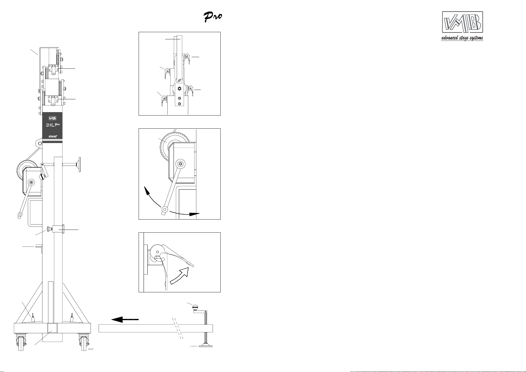
3.1 - Place the tower only in strong and level
surfaces.
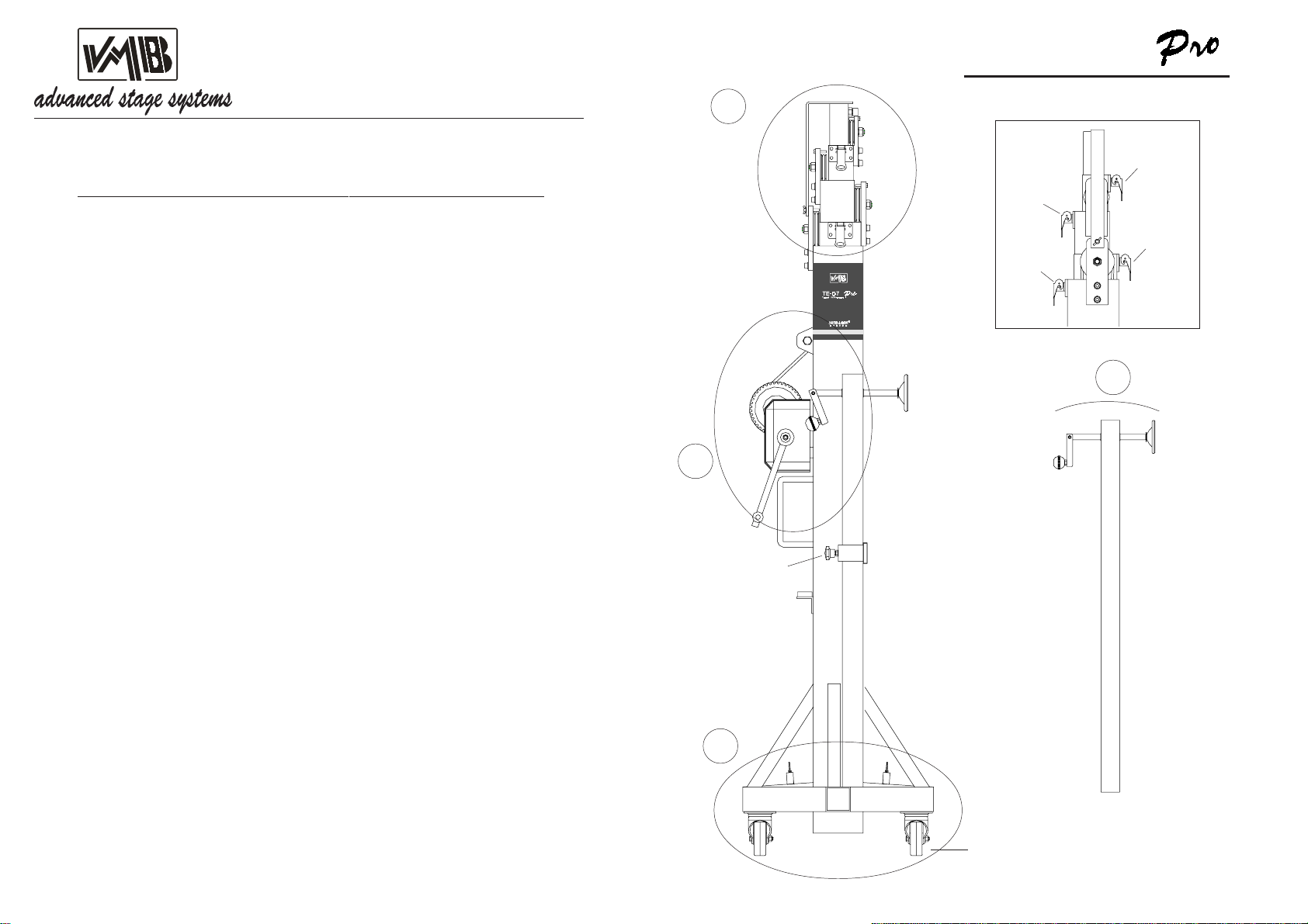
3.2-Verifythatthelegsareinsertedandtightly
fastened by the safety catches (R).
3.3 - Verify that the tower is in a vertical
positionbymeansofthespiritlevel(F)placed
in the main section. Adjust, if necessary, with
the disc feet supports (Q), rotating the hand
crank (H).
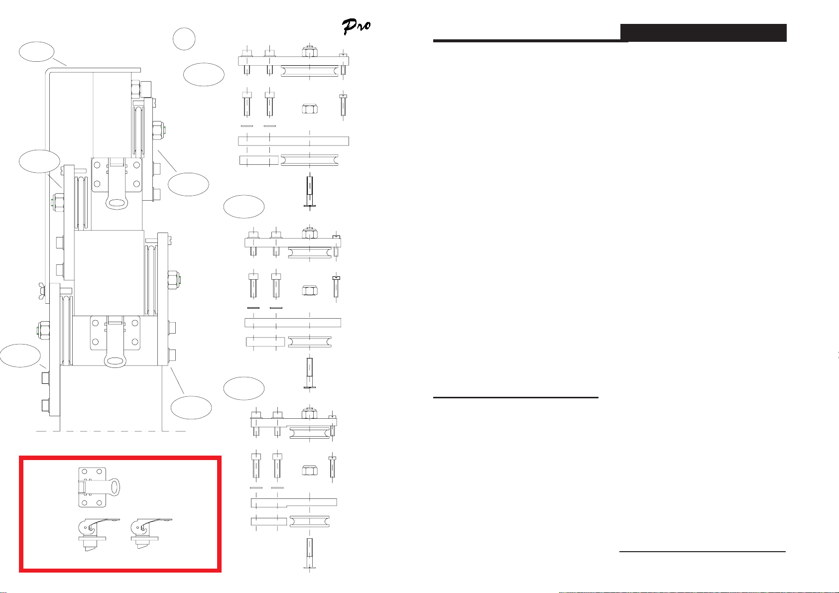
3.4 - Verify that the elevator tower is blocked
inthe workingpositionby meansofthe safety
catches (M1, M2, M3 and M4).Turn thehand
crank one round in a counterclockwise. The
towerlift will be fixed to its working height.
Once the autolock system has been tested,
turn the hand crank in a clockwise until the
cable is tense.
3.5-Tousethetowerintheopenair,placethe
tower in terra firma and protect it against the
wind action.
3.6 - Do not use stairways neither over the
tower nor leaned in it.
3.7-Becarefulwithcables,prominentobjects,
etc. placed above the tower.
3.8 - Do not stay under the load.
3.9 - Do not move the tower when it is lifted
with load.
3.10 - Before any use of the tower verify the
cable,thismustbefreeofcutsandfraying.Do
not use cables in bad conditions.
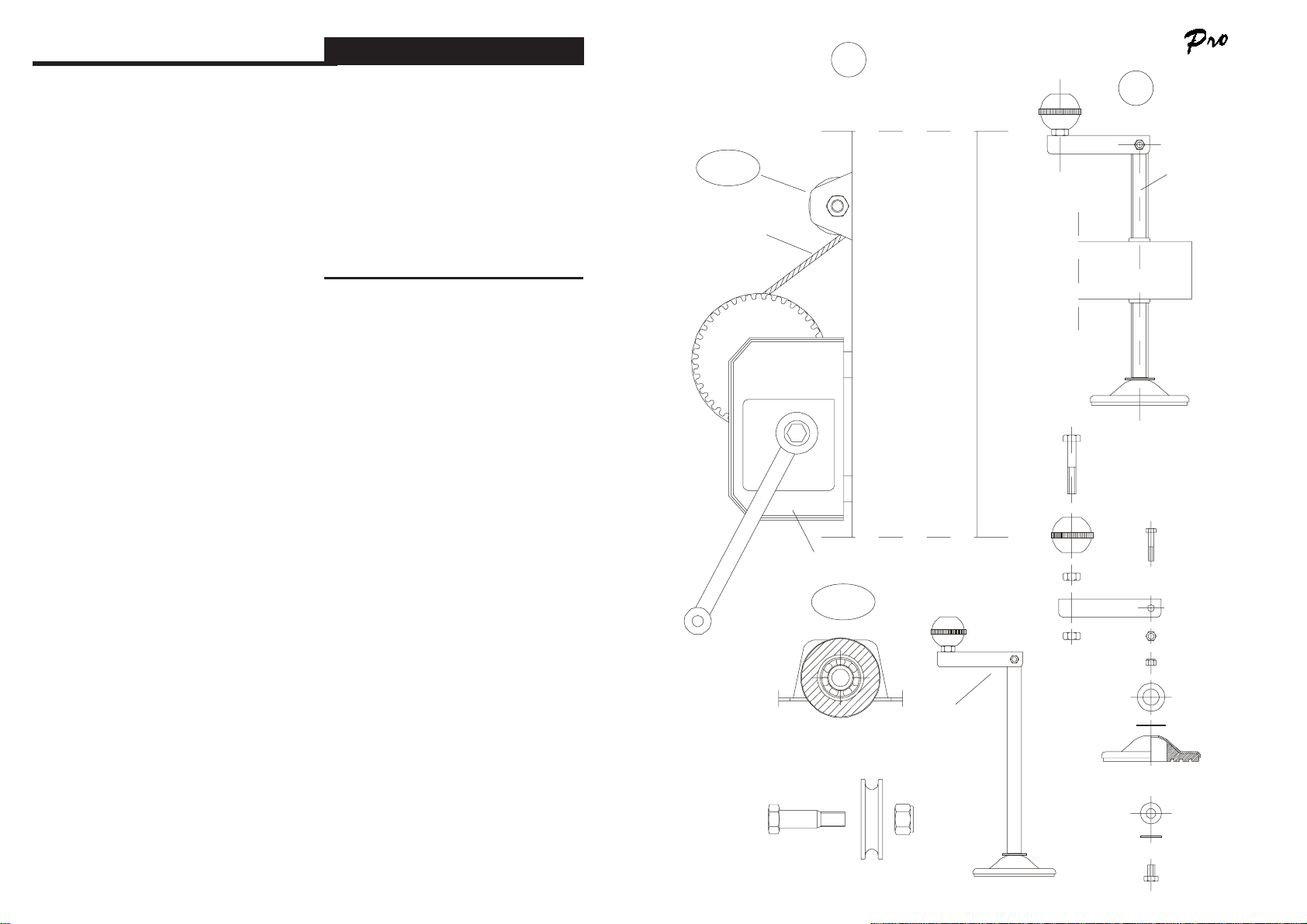
3.11 - Never take to pieces the hand crank of
the winch (W) if the tower is lifted with load.
3.12-Theminimumloadrequiredforaperfect
braking function is 25 Kg. The brake will not
function without this minimum load.
3.13 - Do not apply oil or grease to the brake
mechanism.
3.14 - Not approved for lifting persons.
3.15 - For the transport, lower all the sections
and blockade them with their safety catches.
4. Operation.
4.1 - In order to place the elevator tower in
their working location, put the tower leaned in
their transport wheels (T) on a hard and level
surface.
4.2- Getonthelegs(P)oftheirsupportforthe
transport (S) and insert them in their working
lodging (V) verifying that they are tightly
fastened by the safety catches (R).
4.3-Adjusttheverticalpositionofthetowerby
means of the disc feet supports (Q) rotating
the hand crank (H) in the necessary direction
tomanagethatthebubbleofthespiritlevel(F)
stays centred in the circle.
4.4 - Puttheload on topofthetower usingthe
suitable support, in order to make work the
weightoftheloadonlyintheverticaldirection.
The minimum load must be 25 Kg.
4.5 - Lifting:
Lifttheblockadeonthesafetycatch(BT)
and elevate the tower rotating the hand crank
of the winch (W) in a clockwise (N1), lifting the
load up to desired height.
Mode d'emploi FRANÇAIS
4.6 - Descente:
Libérer les goupilles de sécurité (M1).
Pour libérer les goupilles de sécurité, il faut
éleverlégèrementlachargeaveclecabestan
afin de les lacher. En position normale de
travail, le poids de la charge empêche de
libérer les goupilles. Une fois la goupille de
sécurité libérée (M1), tourner la manivelle du
cabestant dans le sens inverse des aiguilles
d´une montre (N2) jusqu´à ce que la charge
soit au niveau du premier tronçon. Libérer la
goupille (M2) et continuer d´abaisser la tour
élévatricejusqu´àcequeledeuxièmetronçon
soitbaisséaumaximum.Débloquerlagoupille
(M3) et continuer d´abaisser la charge afin
quelatourélévatricesoitcomplètementrepliée
et soit à sa hauteur minimum.
4.7 - Pour transporter la tour élévatrice, il faut
laplier enabaissantcomplétementlestronçons
etenlesfixantaveclescalesdetransportBT.
Replacerensuitelespiedsdansleurssupports
(S)enn'oubliantpasdeserrerlesmolettes(J)
afin de les maintenir en place.
5. Entretien.
5.1- Vérifierrégulièrementlecâble(boucles,
plis, rupture de brin, usure anormale ). Un
câble abîmé doit être remplacé
immédiatement. Ne jamais utiliser le pied
avec un câble défectueux. Utiliser
exclusivementuncâblerépondantàlanorme
DIN 3060.
5.2 - L'appareil à été lubrifié en usine. Il est
cependant recommandé de procéder
régulièrement à la lubrification de tous les
mécanismestournantstelsquerouesdentées,
poulies et roulements, axe de treuil et axe de
manivelle, profils.
ATTENTION:
Ne jamais lubrifier le mécanisme de
freinage.
Lesrondellesdumécanismede freinont
été lubrifiées en usine avec une graisse
spéciale. L'utilisation d'une autre graisse
altérerait grandement l'efficacité du freinage.
Il n'est pas nécessaire de graisser ce
mécanisme.
5.3 - Le pied TE-076 PRO doit être inspecté
annuellement par un personnel qualifié.
5.4-Afindegarantirunbonfonctionnementet
une sécurité maximale, il doit être fait usage
des pièces détachées en provenance du
fabriquant. Toute réclamation sera nulle en
cas de non respect de cette clause.
5.5-Ilestnécessairelorsdetoutecommande
d'indiquer le numéro de pièce figurant sur la
liste jointe à ce manuel.

Mode d'emploi FRANÇAIS
3. Précautions d'emploi.
3.1 - Placer le pied sur une surface dure et
horizontale.
3.2 - Vérifierqueles pieds sontverrouillés(R)
dans leur logement.
3.3-Vérifierquelepiedestenpositionverticale
au moyen du niveau à bulle (F) placé dans le
tronçon principale. Ajuster si nécessaire les
vérins (Q), au moyen de la manivelle (H).
3.4 - Lorsque le pied sera à sa hauteur
définitive, vérifier le bon enclenchement des
goupilles de sécurité (M1, M2, M3).
3.5-Encasd'utilisationenextérieur,neplacer
lapied quesur une surfacedure etélinguer si
nécessaire en cas de vent.
3.6-Nepasappuyerd'échellecontreoudans
le pied.
3.7 - Veiller à ne pas accrocher des câbles et
autres objets placés au dessus du pied.
3.8 - Ne pas stationner sous la charge.
3.9 - Ne pas déplacer le pied lorsqu'il est
déployé et chargé.
3.10 - Avant toute utilisation, vérifier le bon
étatgénéral ducâble. En casde doute,il vaut
mieux renoncer à son usage avant le
remplacement du câble.
3.11 - Il est interdit de démonter la manivelle
du treuil (W) lorsque celui-ci est en tension.
3.12 - La charge minimale pour un bon
fonctionnement du frein est de 25 Kg. En
dessous de cette charge, le frein est sans
effet.
3.13 - Ne pas mettre d'huile ou graisse sur le
méchanisme du frein.
3.14 - Ne pas utiliser ce pied pour l'élévation
de personnes.
3.15 - Pour le transport, descendre tous les
tronçons et les bloquer avec les supports BT.
4. Utilisation.
4.1 - Mettre le pied en position sur ses
roulettes(T)surunesurfacedureethorizontale.
4.2- Enleverlespieds (P) deleur dispositifde
transport (S) et les enfoncer dans leurs
logements(V)ens'assurantque les goupilles
(R) soient bien verrouillées.
4.3 - Ajuster la position verticale en tournant
danslabonnedirectionlesmanivelles(H)des
vérins (Q) de sorte que la bulle du niveau (F)
apparaisse dans le cercle.
4.4 - Débloquer le support de transport (BT).
Mettre en place la charge en se servant d'un
accessoiresupportadécuatetveilleràceque
la charge ne puisse se déplacer que dans un
planvertical.Lachargeminimaleestde25Kg.
Celle-ci se bloquera automatiquement dans
n´importequellepositiongrâceausystèmede
sécurité automatique Auto Lock.
4.5 - Elévation:
Tourner la manivelle du cabestan (W)
dans le sens des aiguilles d´une montre (N1)
pour élever la charge jusqu´à hauteur voulue
tout en vérifiant que les goupilles de sécurité
dusystèmeAutoLocksontactivéesetqu´elles
s´enclavent, bloquant automatiquement les
tronçons.
Operating instructions ENGLISH
4.6 - Lowering:
The manoeuvre of lowering is obtained
by the opposite way. Lift the blockade on the
safetycatch(M1)androtatethehandcrankof
thewinchin acounterclockwise(N2)lowering
the load until that the third profile would be
completely folded. Lift the blockade on the
safety catch (M2) and continue lowering the
tower until that this second profile would be
completely folded. Lift the blockade on the
safety catch (M3) and continue lowering the
load until that the tower would be completely
folded down to its minimum height.
Thetowercanbeleftinanyintermediate
position wich would be necessary, the same
as lifting the load.
4.7-Forthetransportofthetowerisnecessary
to fold the tower lowering completely all the
profiles, blockading them with the safety
catches (BT). Get out the legs lifting the
blockadeonthecatches andput themintheir
transport lodging (S). Press the fastening
screw (J).
5. Maintenance.
5.1 - The cable is to be regulary checked for
wear(ie:kinks,singlestrundbreakage).Faulty
cables must be replaced immediately. Do not
use the elevator tower with faulty cables.
Only use handle cables DIN 3060.
5.2-Theelevatortowerhasbeenlubricatedin
theworkshop.Itisneverthelessrecommended
thatoilisregularyappliedtothegeardrive,the
bearing bushes on the drive shaft and to the
drum hub, the thread of the handle and the
profiles of the tower.
ATTENTION:
Donotapplyoilorgreasetothebrake
mechanism.
The brake washers have been
pregreased with an special warmth and
pressure resistant grease. Do not use other
greases as this will effect the winch brake
performance.
It is not necessary greasing the brake
washers.
5.3- TheelevatortowerTE-076PROmustbe
inspected by trained personnel at least once
annually.
5.4 - In order to maintain this guarantee of
function and safety, original parts of the
manufacturer's design must be used.
Theuserforfeitsallrightstoclaimifparts
otherthanthoseofthemanufacturerareused
or modifies the product in any other way.
5.5 - When any spare part would be required,
itisnecessarytoindicateitsreferencenumber,
wich is included in the spare parts of this
manual.

VMB ESPAÑOLA S.A.
Pol. Ind. Picassent - Calle 2, final - 46220 Picassent (VALENCIA) Spain
Tel.: +34 902 34 10 34 - Fax: +34 961 22 11 77
Mode d'emploi FRANÇAIS
SECTIONS
1. Introduction.
2. Données techniques.
3. Précautions d'emploi.
4. Utilisation.
5. Entretien.
1. Introduction.
Cher utilisateur,
Le but du présent mode d'emploi est de vous
permettre l'utilisation du pied VMB TE-076
PRO avec le maximum d'efficacité et de
sécurité; c'est pourquoi nous vous invitons à
prendre connaissance de ce document avec
laplusgrandeattentionetdetenircomptedes
informations techniques qui s'y trouvent.
Nos produits subissent des test rigoureux
avant toute production qui est elle-même
sévèrement contrôlée tout au long du
processus de fabrication.
Dans le but de mantenir intactes les clauses
degarantie du produit, il est impératif de faire
usage exclusivement des composants
d'origine;toutmanquementàcet impératif ou
toute modification de quelque nature que ce
soit rendra caduque toute application de la
garantie.
VMB se réserve le droit d'apporter toute
modificationàcesproduitssansavispréalable.
Tote commande ou question relative aux
pièces détachées doit être accompagnée du
type de pied, de l'année de construction ainsi
que du numéro de série de l'appareil.
2. Données techniques.
2.1 - Pied élévateur TE-076 PRO.
2.2-Elévationàdifférenteshauteursdetoutes
charges destinées à l'éclairage.
2.3 - Charge maximale : 200 Kg.
2.4 - Charge minimale : 25 Kg.
2.5 - Hauteur maximale : 6,50 m.
2.6 - Hauteur minimale : 1,75 m.
2.7 - Surface de base : 2,47 x 2,47 m.
2.8 - Tare : 95 Kg.
2.9 - Matiére : profils d'acier DIN 2394.
2.10-Quatreprofiléstélescopiquesactionnés
par câble d'acier circulant dans des poulies à
gorge sur roulements à billes.
2.11 - Treuil : 500 Kg. de charge maximale
avec frein automatique.
Certifié à Düsseldorf suivant DIN 15020 et
VBG 8 numéro 93 310.
2.12-Câble:AcierDIN3060180Kg/mm2anti
torsión.
2.13 - Câble diamètre : 6 mm.
2.14.- Fixation des tronçons de la tour
élévatrice à hauteur de travail par des
goupilles de sécurité système AUTOLOCK.
2.15 - Vérins réglables équipés de disques
antidérapants.
2.16 - Fixation des pieds par enclenchement
de goupilles de sécurité.
2.17-Niveauàbulleafindevérifierlaverticalité
du pied.
2.18 - Protection anti-rouille et finition en zinc
électrolytique.
2.19 - Roulettes libres pour le transport du
pied replié.
CERTIFICATION OF TOWERLIFT TE-076 PRO
VMB ESPAÑOLA, S.A. hereby declares that the towerlifts for lighting equipment, model
TE-076 PRO, correspond to the following specifications:
TYPE OF MACHINE
MODEL
DESCRIPTION
STANDARD
RESULTS
Telescopic towerlift.
TE-076 PRO
Telescopic elevator with 5 sections.
Minimum height : 1.75 m.
Maximum height: 6.50 m.
Mínimum load: 25 Kg (250 N).
Maximum load: 200 Kg (2.000 N)
Area of base 2.47 x 2.47 m.
AL-KO elevating winch.
VBG 70 (GUV 6.175) / GUV 66.15
The telescopic towerlift is used for vertical liftings and for holding
up a weight indoor (using a fixing in accordance with static rules, it
can also be used in open-air spaces).
With the elevated load and its safety catches blocked, the towerlift
corresponds to the standard of the VBG 70 (GUV 6.15).
14. 03. 97. Engineer Olaf V. Brandt
The VMB towerlift model TE-076 PRO supplied byVMB ESPAÑOLA, S.A. corresponds to the
verified sample.
Vicente Matali
Technical Director

PRÜFBESCHEINIGUNG TE-076 PRO
VMB Española, S.A. bestätigt hiermit, daß die Towerlifte, Modell TE-076 PRO, den
folgenden Spezifikationen entsprechen.
GERATEART
TYPBEZEICHNUNG
BESCHREIBUNG
PRÜFGRUNDLAGEN
PRÜFERGEBNIS
Traversenlift.
TE-076 PRO
5-teiliger Traversenlift.
Mín.Höhe : 1.75 m.
Max.Höhe : 6.50 m.
Min Hebelast : 25 Kg (250 N).
Max Hebelast. : 200 Kg (2.000 N)
Standfläche: 2.47 x 2.47 m.
Seilwinde des Fabrikats AL-KO.
VBG 70 (GUV 6.175) / GUV 66.15
Der traversenlift dient zum senkrechten Anheben von Lasten und
dem Halten von angehobenen Lasten innerhalb geschlossener Raüme
(bei Verwendung einer geeigneten Seilabspannung nach statischen
Erfordernissen auch ausserhalb geschlossener Raüme).
Bei angehobener Last und verriegelten Sicherheitsbolzen erfüllt der
Traversenlift die Anforderungen der VBG 70 (GUV 6.15).
14. 03. 97. Ing. Olaf V. Brandt
Der von VMB Española, S.A. gelieferte Towerlift, Modell TE-076 PRO entsprich dem geprüften Muster.
Vicente Matali
Tech. Dir.
VMB ESPAÑOLA S.A.
Pol. Ind. Picassent - Calle 2, final - 46220 Picassent (VALENCIA) Spain
Tel.: +34 902 34 10 34 - Fax: +34 961 22 11 77
Bedienungsanleitung DEUTSCH
Inhaltsverzeichnis
1. Einführung.
2. Technische Daten.
3. Sicherheitsmaßnahmen.
4. Bedienungsanleitung.
5. Wartung.
1. Einführung.
Sehr geehrter Kunde,
die vorliegende Betriebsanleitung wurde mit
dem Zweck erstellt, eine zuverlässige
Bedienung des TE-076 PRO Hebeturms zu
ermöglichen. Lesen Sie bitte die
Betriebsanleitung vor Inbetriebnahme
sorgfältig durch.
BittebeachtenSieauchdietechnischeDaten.
Unsere Produkte unterliegen strengsten
Prüfungen und Kontrollen bei der Fertigung.
Es sind ausschließlich Original-Ersatzteile zu
verwenden. Für den Anwender werden alle
Gewährleistungsansprüche aufgehoben,
wenn er Nicht-Original-Ersatzeile verwendet
bzw.ÄnderungenamProduktselbstvormimmt.
2. Technische daten.
2.1 - Hebeturm, Typ TE-076 PRO.
2.2 - Das Gerät ist zum senkrechten Heben
von Lasten, wie auf verschiede Höhen,
konzipiert worden.
2.3 - Zulässige Hubkraft : 200 Kg.
2.4 - Mindesthublast : 25 Kg.
2.5 - Zulässige Hubhöhe : 6,35 m.
2.6 - Mindeshubhöhe : 1,75 m.
2.7 - Grundplattenfläche : 2,47 x 2,47 m.
2.8 - Transportgewicht : 95 Kg.
2.9 - Werkstoff : Stahlprofil nach DIN 2394.
2.10 - Teleskopierbares System, bestehend
aus vier, von einem über genufete Rollen mit
WälzlagerngeführtenStahlseilangetriebenen
Abschnitten.
2.11-DieWinde,miteinerzulässigenHublast
von 500 Kg, ist mit einer automatischen
Lasthaltebremse ausgestattet. In Düsseldorf
nachDIN 15020undVBG 8unter Nr.:93310
zugelassen.
2.12 - Seil : aus Stahl nach DIN 3060. Güte
180 Kg/mm2verwindungssteif.
2.13 - Seildurchmesser : 6 mm.
2.14 - Arretieren der Liftsegmente auf die
Arbeitshöhe über automatische
Sicherheitsbolzen ( Auto-Lock-System ).
2.15 - Ausleger mit verstellbaren Spindeln
und rutschfesten Gummifüßen.
2.16 - Verankerung der Ausleger über
Sicherheitsklinken.
2.17 - Wasserwaage zum Einstellen der
senkrechten Turmlage.
2.18-KorrosionsschutzundVeredelungdurch
elektrolytische Verzinkung.
2.19 - Transportrollen zum Bewegen des
Turms bei senkrechter und eingefahrener
Stellung zur Arbeitsstelle.
3. Sicherheitsmaßnahmen.
3.1- DenHubturmnuraufhartenundebenen
Flächen aufstellen.
3.2-AchtenSiebittedarauf,daßdieAusleger
vollkommen eingeschoben und mittels der
Sicherheitsbolzen befestigt sind (R).

Bedienungsanleitung DEUTSCH
3.3 - Mittels der auf der Grundplatte
vorhandenen Wasserwaage (F) prüfen Sie
bitte,obder Turmsenkrechtsteht.Bei Bedarf
mittels des Stelltellers (Q) durch drehen der
Spindelkurbel(H)inentsprechenderRichtung
die Turmlage einstellen.
3.4 - Prüfen Sie bitte, ob der turm in seiner
Arbeitsstellung mittels der Sicherheitsbolzen
(M1, M2, M3) fixiert ist.
3.5 - Bei Freiluftanwendungen, den Turm auf
festen Boden stellen und mittels Seilanker
gegen die Windbelastung schützen.
3.6 - Keine Leiter auf dem Turm verwenden
bzw. auf diesen anlehnen.
3.7-AchtenSiebitteaufherausragendeTeile
(wie Seile Drähte, Deckenvorsprünge usw.)
oberhalb des Turmes.
3.8 - Niemand soll sich unter dem Turm
aufhalten.
3.9 - Den Turm nicht bewegen, wenn dieser
unter Last steht und ausgefahren ist.
3.10 - Vor der Verwendung des Turms den
Seilzustand kontrollieren. Das Seil darf keine
drahtbrüche bzw. Quetschstellen aufweisen.
Unter keinen Umständen Seile in schlechtem
Zustand verwenden.
3.11 - Niemals die Windekurbel (W) bei unter
Last stehendem und ausgefahrenen Turm
abbauen.
3.12 - Die Mindestlast für eine reibungslose
Funktion der Bremse beträgt 25 Kg. Ohne
dieseMindestlastsprichtdieBremsenichtan.
3.13-DieLastdruckbremsewederschmieren
noch ölen.
3.14 - Der Heberturm ist nicht als
Personenaufzugzugelassen.
3.15 - Zum Transport sind die Liftsegmente
einzufahren,wobeidieEinzelsegmentemittels
der Transportsicherung BT fixiert werden.
4. Bedienungsanleitung.
4.1 - Den Hebeturm auf den Transportrollen
(T)abgestütztaufeineebeneundfesteFläche
an der Arbeitsstelle aufstellen.
4.2 - Die Ausleger (P) aus der
Transporhalterung (S) herausnehmen und in
derenArbeitsaufnahmen(V)volleinschieben.
Dabei achten Sie bitte darauf, daß sie mittels
der Sicherheitsbolzen (R) befestigt sind.
4.3 - Die senkrechte Turmlage über die
verstellbaren Spindel (Q) durch Drehen der
kurbel (H) in entsprechender Richtung zum
Zentrieren der Wasserwaagenblase (F) an
der Kreismitte einstellen.
4.4- DieTransportsicherungBT lösen.Diezu
hebende Last auf dem Turm mittels eines
geeigneten Trägers so aufstellen, daß das
Lastgewicht nur senkrecht wirkt. Die
Mindestlast muß 25 Kg. betragen. Der lift
bleibt durch das automatische Auto-Lock-
System automatisch in jeder beliebigen
Position arretiert.
4.5 - Heben:
DenTurmdurchDrehenderWindekurbel
(W)imUhrzeigersinn(N1),aufdiegewünschte
Höhebringen.PrüfenSiebitte,dassdieBolzen
desAuto-Lock-SystemsinSchaltpositionsind
und einrasten, so dass die Abschnitte
automatisch fixiert werden.
Bedienungsanleitung DEUTSCH
4.6 - Senken:
Den Sicherheitsbolzen (M1) entriegeln.
UmdieSicherheitsbolzenzuentsperren,muß
mandieLastmitderWindeleichtanheben.In
der normalen Arbeitsposition verhindert das
Lastgewicht das Entriegeln der Bolzen. Nach
dem Entriegeln des Sicherheitsbolzen (M1),
dieKurbelderWindegegendenUhrzeigersinn
(N2) drehen bis beim Senken der Last
Turmabschnitt 1 voll heruntergefahren ist.
Den Bolzen (M2) entriegeln und den Turm
weiter nach unten senken bis Abschnitt 2 voll
heruntergefahren ist.
Bolzen (M3) entriegeln und die Last weiter
senken bis der Hebeturm vollkommen bis zur
Mindesthöhe heruntergefahren ist.
4.7 - Zum Transport sind die Liftsegmente
einzufahren,wobeidieEinzelsegmentemittels
derTransportsicherungBTfixiertwerden.Die
Ausleger entsperren und diese in ihre
Transportstellung (S) bringen.
4.8 - Für den transport des Turmes ist dieser
durch Senken der Einzelabschnitte
herunterzufahren,wobeidieEinzelabschnitte
mittels der Sicherheitsbolzen (BT) befestigt
werdenmüssen.DieAuslegerentsperrenund
diese in ihre Transportstellung (S) bringen.
Die Befestigungsschrauben (J) anziehen.
5. Wartung.
5.1 - Regelmäßig den Seilzustand
kontrollieren.WeisteinSeilDrahtbrüchebzw.
Quetschungen auf, ist es sofort durch ein
meueszuersetzen.UnterkeinenUmständen
den Hebeturm mit Seilen in schlechtem
Zustand verwenden.
Nur verwindungssteifes Stahlseil nach
DIN 3060 verwenden.
5.2 - Der Hebeturm wird werkseitig komplett
geschmiertgeliefert.Eswirdjedochempfohlen,
regelmäßig (je nach Bedarf) das Zahnrad der
Winde, die Wälzlager der Antriebswelle und
Hülse,dasKurbelgewindeunddieAbschnitte
zu schmieren.
ACHTUNG:
DieBremsscheibennichteinölenoder
fetten!
5.3 - Der Hebeturm TE-076 PRO sollte von
einer Fachkraft mindestens einmal jährlich
geprüft werden.
5.4 - Für eine kontinuierliche
Bebriebssicherheit sind ausschließlich
Original-Ersatzteile zu verwenden.
Alle Gewährleistungsansprüche sind für den
Anwender aufgehoben, wenn er Nicht-Origi-
nal-Ersatzteile verwendet bzw. Änderungen
am Produkt von selbst vormimmt.
5.5 - Für die Bestellung von Ersatzteilen ist
stets dessen Bestellnummer anzugeben,
welchwe den Stücklisten-Blättern dieser
Anleitung zu entnehmen ist.
VMB Service Deutschland 0251 20 13 23
Other VMB Elevator manuals