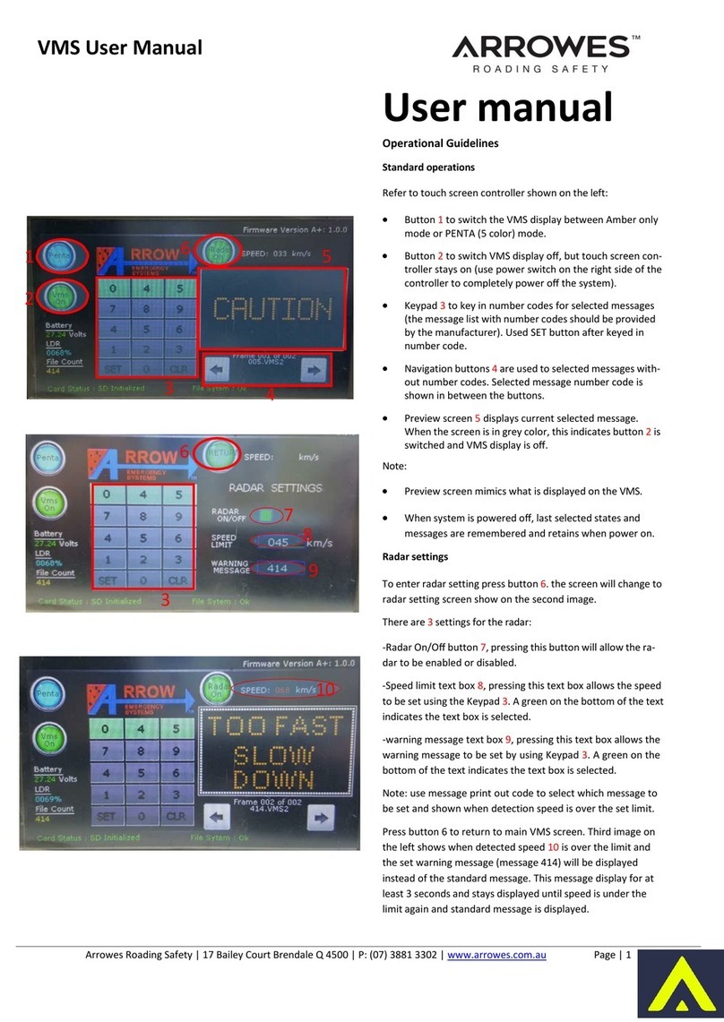
VMIC VMIVME-7586 User manual

VMIVME-7586
PC/AT COMPATIBLE
VMEbus CONTROLLER
PRODUCT MANUAL
DOCUMENT NO. 500-017586-000 B
Revised July 21, 1997
VME MICROSYSTEMS INTERNATIONAL CORPORATION
12090 SOUTH MEMORIAL PARKWAY
HUNTSVILLE, AL 35803-3308
(205) 880-0444
(800) 322-3616
FAX NO.: (205) 882-0859

COPYRIGHT AND TRADEMARKS
© Copyright 1996. The information in this document has been carefully checked and is believed to be
entirely reliable. While all reasonable efforts to ensure accuracy have been taken in the preparation of this
manual, VMIC assumes no responsibility resulting from omissions or errors in this manual, or from the use of
information contained herein.
VMIC reserves the right to make any changes, without notice, to this or any of VMIC’s products to improve
reliability, performance, function, or design.
VMIC does not assume any liability arising out of the application or use of any product or circuit described
herein; nor does VMIC convey any license under its patent rights or the rights of others.
For warranty and repair policies, refer to VMIC’s Standard Conditions of Sale.
AMXbus
, BITMODULE
, COSMODULE
, DMAbus
, IOWorks
, IOWorks Access
, IOWorks
Foundation
, IOWorks man figure™, IOWorks Manager™, IOWorks Server™, MAGICWARE
,
MEGAMODULE
, PLC ACCELERATOR (ACCELERATION)
, Quick Link
, Soft Logic Link
, SRTbus
,
TESTCAL
, “The Next Generation PLC”
, The PLC Connection
, TURBOMODULE
, UCLIO
, UIOD
,
UPLC
, Visual IOWorks
, Visual Soft Logic Control(ler)™,
VMEaccess
,
VMEmanager
,
VMEmonitor
,
VMEnet
, VMEnet II
, and
VMEprobe
are trademarks of VME Microsystems International Corporation.
The I/O man figure, UIOC®
,
the VMIC logo, and
WinUIOC
® are registered trademarks of VME
Microsystems International Corporation.
Microsoft, Microsoft Access, MS-DOS, Visual Basic, Visual C++, Win32, Windows, and XENIX are
registered trademarks and Windows NT is a trademark of Microsoft Corporation.
Pentium is a registered trademark of Intel Corporation.
Other registered trademarks are the property of their respective owners.
VME Microsystems International Corporation
All Rights Reserved
This document shall not be duplicated, nor its contents used for any
purpose, unless granted express written permission from VMIC.
®
UIOC
(VMIC logo)
WinUIOC
(I/O man figure)
(IOWorks man figure)

VMIVME-7586 Error Notification
Because of a recently discovered design flaw in the VIC64 (Cypress
Semiconductor) used to implement the VMEbus interface on the
VMIVME-7586, VMIC warns users that a malfunction may occur. The
following paragraphs below provide information from Cypress concerning
the conditions that must be present to cause this malfunction.
Cypress Erratum:
The following paragraphs came directly from the 6/13/97 Cypress Erratum (Reference No.95):
Lword and A7-A1 are driven on the VMEbus by a VIC64 slave that is not the addressed slave to the D64
transaction in progress thus corrupting the data of the transaction.The following condition must be met to see
this failure:
1. Defining this misbehaving VIC64 as the “failing slave” and the transaction in which the failure is
noted the “current transaction.”
2. The failing slave was the addressed slave to the transaction immediately preceding the current
transaction.We define this transaction to be the “preceding transaction.”
3. The preceding transaction was a D64 slave read from the failing slave.
4. The current transaction must be a D64 transaction.
5. The preceding transaction exhibits a local “read ahead” cycle which extends (local PAS+ signal is
asserted) beyond the address broadcast phase (first VMEbus DS1/0 deassertion after AS*
assertion) of the current transaction.
Work around, Hardware:
PAS* must be deasserted before DSB (later deassertion of either DS1/0) of the address broadcast cycle of
the current transaction deasserts.
VMIC’s Response:
These conditions may arise if:
1. You have more than one device that may be slave to 64-bit block transfers and at least one has a
VIC64 chip.
2. Block transfer master(s) can reassert AS* and execute a BLT 64 Address Broadcast quickly (less
than about 100 ns AS* hightime).
The VIC64 as used on the VMIVME-7586 does not cause trouble during Master Mode. In other words, the
VMIVME-7586 can safely do master BLT 64 transactions under all conditions.The described malfunction only
occurs when the VIC64 is a BLT 64
slave
(read
from/by
master)
and
the slave transaction is rapidly followed
by
another
BLT 64 slave transaction
to
another slave.

RECORD OF REVISIONS
REVISION
LETTER DATE PAGES INVOLVED CHANGE NUMBER
VME MICROSYSTEMS INT’L CORP.
12090 South Memorial Parkway
Huntsville, AL 35803-3308 • (205) 880-0444
REV LTR PAGE NO.
iii
A 10/25/96 Release 96-0744
B 07/21/97 Cover and Page iii 97-0539
DOC. NO. 500-017586-000
B

iv
VMIC
SAFETY SUMMARY
THE FOLLOWING GENERAL SAFETY PRECAUTIONS MUST BE OBSERVED DURING ALL PHASES
OF THE OPERATION, SERVICE, AND REPAIR OF THIS PRODUCT. FAILURE TO COMPLY WITH
THESE PRECAUTIONS OR WITH SPECIFIC WARNINGS ELSEWHERE IN THIS MANUAL VIOLATES
SAFETY STANDARDS OF DESIGN, MANUFACTURE, AND INTENDED USE OFTHIS PRODUCT. VME
MICROSYSTEMS INTERNATIONAL CORPORATION ASSUMES NO LIABILITY FOR THE
CUSTOMER'S FAILURETO COMPLY WITHTHESE REQUIREMENTS.
GROUNDTHE SYSTEM
To minimize shock hazard, the chassis and system cabinet must be connected to an electrical
ground. A three-conductor AC power cable should be used. The power cable must either be
plugged into an approved three-contact electrical outlet or used with a three-contact to
two-contact adapter with the grounding wire (green) firmly connected to an electrical ground
(safety ground) at the power outlet.
DO NOT OPERATE IN AN EXPLOSIVE ATMOSPHERE
Do not operate the system in the presence of flammable gases or fumes. Operation of any
electrical system in such an environment constitutes a definite safety hazard.
KEEP AWAY FROM LIVE CIRCUITS
Operating personnel must not remove product covers. Component replacement and internal
adjustments must be made by qualified maintenance personnel. Do not replace components
with power cable connected. Under certain conditions, dangerous voltages may exist even with
the power cable removed. To avoid injuries, always disconnect power and discharge circuits
before touching them.
DO NOT SERVICE OR ADJUST ALONE
Do not attempt internal service or adjustment unless another person, capable of rendering first
aid and resuscitation, is present.
DO NOT SUBSTITUTE PARTS OR MODIFY SYSTEM
Because of the danger of introducing additional hazards, do not install substitute parts or perform
any unauthorized modification to the product. Return the product to VME Microsystems
International Corporation for service and repair to ensure that safety features are maintained.
DANGEROUS PROCEDUREWARNINGS
Warnings, such as the example below, precede only potentially dangerous procedures
throughout this manual. Instructions contained in the warnings must be followed.
DANGEROUS VOLTAGES, CAPABLE OF CAUSING DEATH, ARE PRESENT IN THIS SYSTEM. USE
EXTREME CAUTIONWHEN HANDLING,TESTING, AND ADJUSTING.
WARNING

v
OR
**************
**************
*
*
**
*
*
CAUTION
NOTE:
WARNING
!
OR
GENERAL DEFINITIONS OF SAFETY SYMBOLS USED IN THIS
MANUAL
Instruction manual symbol: the product is marked with this symbol when it is
necessary for the user to refer to the instruction manual in order to protect against
damage to the system.
Indicates dangerous voltage (terminals fed from the interior by voltage exceeding
1000 volts are so marked).
Protective conductor terminal. For protection against electrical shock in case of a
fault. Used with field wiring terminals to indicate the terminal which must be
connected to ground before operating equipment.
Low-noise or noiseless, clean ground (earth) terminal. Used for a signal common,
as well as providing protection against electrical shock in case of a fault. Before
operating the equipment, terminal marked with this symbol must be connected to
ground in the manner described in the installation (operation) manual.
Frame or chassis terminal. A connection to the frame (chassis) of the equipment
which normally includes all exposed metal structures.
Alternating current (power line).
Direct current (power line).
Alternating or direct current (power line).
The WARNING sign denotes a hazard. It calls attention to a procedure, a
practice, a condition, or the like, which, if not correctly performed or adhered to,
could result in injury or death to personnel.
The CAUTION sign denotes a hazard. It calls attention to an operating procedure,
a practice, a condition, or the like, which, if not correctly performed or adhered to,
could result in damage to or destruction of part or all of the system.
The NOTE sign denotes important information. It calls attention to a procedure, a
practice, a condition or the like, which is essential to highlight.
SAFETY SYMBOLS

TABLE OF CONTENTS
VMIVME-7586 PRODUCT MANUAL
vi
CHAPTER 1 - INTRODUCTION .................................................
1-1
SECTION 1 - INTRODUCTION TO THE VMIVME-7586 ....................... 1-1
SECTION 2 - ABOUT THIS MANUAL ................................................... 1-2
SECTION 3 - PRODUCT FAMILY ......................................................... 1-3
SECTION 4 - REFERENCES ................................................................. 1-5
SECTION 5 - PC/AT FEATURES .......................................................... 1-6
SECTION 6 - VMEbus FEATURES ....................................................... 1-8
CHAPTER 2 - INSTALLATION AND SETUP ............................
2-1
SECTION 1 - INTRODUCTION .............................................................. 2-1
SECTION 2 - UNPACKING PROCEDURES ......................................... 2-2
SECTION 3 - HARDWARE SETUP ....................................................... 2-2
SECTION 4 - LED STATUS DEFINITION .............................................. 2-5
SECTION 5 - INSTALLATION ............................................................... 2-5
SECTION 6 - FRONT PANEL CONNECTORS ..................................... 2-6
SECTION 7 - PC/104 EXPANSION SITE .............................................. 2-7
SECTION 8 - BIOS SETUP .................................................................... 2-8
SECTION 9 - CONFIGURING OPERATING SYSTEMS ....................... 2-8

TABLE OF CONTENTS 500-017586-000
vii
VMIVME-7586 PRODUCT MANUA
L
GENERAL RULE REGARDING OPERATING SYSTEMS ............... 2-8
CONFIGURATION EXAMPLES ........................................................ 2-9
Configuring MS-DOS for the VMIVME-7586 ............................... 2-9
Configuring Windows for the VMIVME-7586 ............................... 2-10
CHAPTER 3 - PC/AT FUNCTIONS
................................................... 3-1
SECTION 1 - CPU FUNCTIONAL OVERVIEW ..................................... 3-1
SECTION 2 - PHYSICAL MEMORY ...................................................... 3-2
SECTION 3 - MEMORY AND I/O PORT MAPS .................................... 3-3
MEMORY MAP ................................................................................. 3-3
I/O PORT MAP .................................................................................. 3-4
SECTION 4 - PC/AT INTERRUPTS ....................................................... 3-8
SECTION 5 - ENHANCED I/O PERIPHERAL PORTS .......................... 3-12
SERIAL PORTS ................................................................................ 3-13
PARALLEL PORT ............................................................................. 3-13
SECTION 6 - VIDEO GRAPHICS ADAPTER ........................................ 3-14
SECTION 7 - PC/104 EXPANSION SITE .............................................. 3-15
CHAPTER 4 - VMEbus FUNCTIONS ........................................
4-1
SECTION 1 - INTRODUCTION .............................................................. 4-1
SECTION 2 - VMEbus INTERFACE ...................................................... 4-2
VMEBUS INTERFACE OVERVIEW ................................................. 4-2
VMEBUS INTERFACE HARDWARE ................................................ 4-4
PROGRAMMING THE VMEBUS INTERFACE ................................ 4-6

500-017586-000 TABLEOF CONTENTS
VMIVME-7586 PRODUCT MANUAL
viii
SECTION 3 - VMEbus MASTER OPERATION ..................................... 4-7
REAL MODE ACCESS ..................................................................... 4-8
PROTECTED MODE ACCESS ......................................................... 4-10
128 MBYTE - PROTECTED MODE ACCESS .................................. 4-13
SECTION 4 - VMEbus SLAVE OPERATION ........................................ 4-16
INTERPROCESSOR COMMUNICATIONS ...................................... 4-17
DUAL-PORTED DRAM ..................................................................... 4-21
SLAVE ACCESS MEMORY MAP ..................................................... 4-24
ADDRESS REMAPPING .................................................................. 4-26
SYSTEM CONSIDERATIONS .......................................................... 4-28
SECTION 5 - SYSTEM CONTROLLER FUNCTIONS ........................... 4-31
SECTION 6 - VMEbus INTERRUPT HANDLING .................................. 4-32
SOFTWARE INTERRUPTS .............................................................. 4-36
INTERRUPT ON BERR* ................................................................... 4-36
PERIODIC TIMER INTERRUPT ....................................................... 4-36
INTERRUPT PROCESSING ............................................................. 4-37
SECTION 7 - VMEbus INTERRUPTER ................................................. 4-39
SECTION 8 - VMEbus REQUESTER .................................................... 4-40
SECTION 9 - READ-MODIFY-WRITE CYCLES .................................... 4-40
SECTION 10 - BLOCK TRANSFERS .................................................... 4-42
DRAM REFRESH CONSIDERATIONS ............................................ 4-42
MASTER BLT OPERATION .............................................................. 4-43
SLAVE BLT OPERATION ................................................................. 4-45

TABLE OF CONTENTS 500-017586-000
ix
VMIVME-7586 PRODUCT MANUA
L
SECTION 11 - VME64 FUNCTIONS ...................................................... 4-45
MASTER VME64 OPERATION ........................................................ 4-45
SLAVE VME64 OPERATION ............................................................ 4-45
SECTION 12 - BYTE ORDERING ......................................................... 4-46
BYTE SWAPPING ............................................................................ 4-46
The Byte-Swapping Problem Defined .......................................... 4-47
Byte Swapping and the VMEbus ................................................. 4-48
VMIVME-7586 Byte-Swapping Hardware .................................... 4-49
Master/Slave Byte Swapping ....................................................... 4-51
SECTION 13 - VMIVME-7586 REGISTERS .......................................... 4-52
REGISTER MAPS ............................................................................. 4-52
SYSTEM REGISTER DETAILS ........................................................ 4-58
General Purpose Command Register .......................................... 4-58
Product ID Register ..................................................................... 4-61
VIC Base Register ....................................................................... 4-61
Extended/Standard Address Register ......................................... 4-62
On-Board Video Status Register ................................................. 4-63
128 Mbyte Mode Enable Register ............................................... 4-63
Rearm Interrupt Register ............................................................. 4-63
Slave Address Mask/Compare Registers .................................... 4-63
Size Register ............................................................................... 4-63
Remap Register ........................................................................... 4-64
INTERRUPT ACKNOWLEDGE REGISTER DETAILS ..................... 4-64
VIC REGISTER DETAILS ................................................................. 4-65
VMEbus Interrupter Interrupt Control Register ............................ 4-65
VMEbus Interrupt Control Registers ............................................ 4-66
DMA Status Interrupt Control Register ........................................ 4-67
Local Interrupt Control Registers ................................................. 4-68
ICGS Interrupt Control Register ................................................... 4-70
ICMS Interrupt Control Register .................................................. 4-70
Error Group Interrupt Control Register ........................................ 4-71
ICGS Interrupt Vector Base Register ........................................... 4-73
ICMS Interrupt Vector Base Register .......................................... 4-73
Local Interrupt Vector Base Register ........................................... 4-74

500-017586-000 TABLEOF CONTENTS
VMIVME-7586 PRODUCT MANUAL
x
Error Group Interrupt Vector Base Register ................................. 4-75
Interprocessor Communications Registers .................................. 4-76
VMEbus Interrupt Request/Status Register ................................. 4-76
VMEbus Interrupt Vector Base Registers .................................... 4-76
Transfer Timeout Register ........................................................... 4-77
Local Bus Timing Register ........................................................... 4-80
Block Transfer Definition Register ............................................... 4-81
Interface Configuration Register .................................................. 4-82
Arbiter/Requester Configuration Register .................................... 4-84
Address Modifier Source Register ............................................... 4-85
Bus Error Status Register ............................................................ 4-86
DMA Status Register ................................................................... 4-87
Slave Select 0 Control Register 0 ................................................ 4-89
Slave Select 0 Control Register 1 ................................................ 4-91
Slave Select 1 Control Register 0 ................................................ 4-94
Slave Select 1 Control Register 1 ................................................ 4-96
Release Control Register ............................................................. 4-99
Block Transfer Control Register ................................................... 4-100
Block Transfer Length Registers .................................................. 4-102
System Reset Register ................................................................ 4-103
INTERPROCESSOR COMMUNICATIONS REGISTERS ................ 4-103
Interprocessor Communications Switch Register ........................ 4-104
Interprocessor Communication Registers .................................... 4-105
VIC Version Register ................................................................... 4-105
Reset/Halt Status Register ........................................................... 4-105
Mailbox Semaphore Register ....................................................... 4-106
Set/Clear ICGS Switch Registers (Slave-Only) ........................... 4-108
Set/Clear ICMS Switch Registers (Slave-Only) ........................... 4-108
CHAPTER 5 - MAINTENANCE ..................................................
5-1
SECTION 1 - MAINTENANCE ............................................................... 5-1
SECTION 2 - MAINTENANCE PRINTS ................................................. 5-1
APPENDIX A - CONNECTOR PINOUTS ..................................
A-1
SECTION 1 - INTRODUCTION .............................................................. A-1

TABLE OF CONTENTS 500-017586-000
xi
VMIVME-7586 PRODUCT MANUA
L
SECTION 2 - ETHERNET CONNECTOR PINOUT ............................... A-3
SECTION 3 - FLOPPY DRIVE CONNECTOR PINOUT ........................ A-4
SECTION 4 - IDE HARD DRIVE CONNECTOR PINOUT ..................... A-5
SECTION 5 - KEYBOARD CONNECTOR PINOUT .............................. A-6
SECTION 6 - PC/104 CONNECTOR PINOUT ....................................... A-7
SECTION 7 - PRINTER CONNECTOR PINOUT ................................... A-9
SECTION 8 - SERIAL CONNECTOR PINOUT ..................................... A-10
SECTION 9 - VIDEO CONNECTOR PINOUT ....................................... A-11
SECTION 10 - VMEbus CONNECTOR PINOUT .................................. A-12
APPENDIX B - ETHERNET OPTION .........................................
B-1
SECTION 1 - INTRODUCTION .............................................................. B-1
SECTION 2 - ETHERNET SOFTWARE COMPATIBILITY ................... B-2
SECTION 3 - ETHERNET DRIVER SOFTWARE .................................. B-3
SECTION 4 - ETHERNET DIAGNOSTIC SOFTWARE ......................... B-3
SECTION 5 - TECHNICAL DETAILS .................................................... B-5
APPENDIX C - FLASH MEMORY OPTION ...............................
C-1
SECTION 1 - INTRODUCTION .............................................................. C-1
SECTION 2 - PREPARING THE FLASH MEMORY .............................. C-2
SECTION 3 - COPYING FILES TO FLASH MEMORY ......................... C-3
SECTION 4 - USING FLASH MEMORY AS BOOT DEVICE ................ C-4

500-017586-000 TABLEOF CONTENTS
VMIVME-7586 PRODUCT MANUAL
xii
SECTION 5 - REPROGRAMMING FLASH MEMORY .......................... C-4
SECTION 6 - TECHNICAL DETAILS .................................................... C-4
SECTION 7 - PROGRAMMING ............................................................. C-6
APPENDIX D - BASIC INPUT / OUTPUT SYSTEM .................
D-1
SECTION 1 - INTRODUCTION .............................................................. D-1
SECTION 2 - STANDARD FEATURES ................................................. D-1
SECTION 3 - QUICK SETUP ................................................................. D-2
SECTION 4 - PROGRAM DESCRIPTION ............................................. D-5
USER INTERFACE ........................................................................... D-6
CONTROL KEY SUMMARY ............................................................. D-7
SECTION 5 - PROGRAM MENUS AND MENU ITEMS ........................ D-8
MAIN MENU ...................................................................................... D-8
System Time ................................................................................ D-9
System Date ................................................................................ D-9
Diskette A:/B: ............................................................................... D-9
Video System ............................................................................... D-9
Large Disk Mode .......................................................................... D-9
System Memory/ Extended Memory ............................................ D-9
IDE Adapter 0 Master/IDE Adapter 0 Slave Sub-menus ............. D-10
Autotype Fixed Disk ..................................................................... D-10
Type ............................................................................................. D-11
Cylinders ...................................................................................... D-13
Heads ........................................................................................... D-13
Sectors/Track ............................................................................... D-13
Write Precomp ............................................................................. D-13
MEMORY CACHE SUB-MENU ........................................................ D-14
Internal Cache .............................................................................. D-15
External Cache ............................................................................ D-15
Cache Shadow Region ................................................................ D-15

TABLE OF CONTENTS 500-017586-000
xiii
VMIVME-7586 PRODUCT MANUA
L
Noncacheable Region ................................................................. D-15
MEMORY SHADOW SUB-MENU ..................................................... D-16
System Shadow ........................................................................... D-17
Video Shadow .............................................................................. D-17
Shadow Memory Regions ............................................................ D-17
C800 - CFFF ................................................................................ D-18
D000 - DFFF ................................................................................ D-18
E000 - EFFF ................................................................................ D-18
BOOT OPTIONS SUB-MENU ........................................................... D-19
Keyboard ..................................................................................... D-19
Boot Sequence ............................................................................ D-20
SETUP Prompt ............................................................................ D-20
POST Errors ................................................................................ D-20
Floppy Check ............................................................................... D-20
Summary Screen ......................................................................... D-21
KEYBOARD FEATURES .................................................................. D-21
NumLock ...................................................................................... D-22
Key click ....................................................................................... D-22
Keyboard Autorepeat Rate .......................................................... D-23
Keyboard Autorepeat Delay ......................................................... D-23
SECTION 6 - EXITING THE PhoenixBIOS ........................................... D-23
EXIT MENU ....................................................................................... D-23
Save Changes & Exit ................................................................... D-24
Discard Changes & Exit ............................................................... D-24
Load Default Values .................................................................... D-24
Load Previous Values .................................................................. D-24
Save Changes ............................................................................. D-25
SECTION 7 - STATUS AND ERROR MESSAGES ............................... D-26

LIST OF FIGURES
VMIVME-7586 PRODUCT MANUAL xiv
Figure 1-1 VMIVME-7586 Board View ..................................................
1-3
Figure 1-2 VMIVME-7586 Partial Block Diagram ................................
1-7
Figure 1-3 VMIVME-7586 VMEbus Functions .....................................
1-9
Figure 2-1 I/O Port and Jumper Locations .........................................
2-3
Figure 2-2 LED Position on the Front Panel .......................................
2-5
Figure 2-3 PC/104 Mechanical Connection ........................................
2-7
Figure 3-1 Connections Between the PC Interrupt Logic Controller
and the VMEbus ............................................................
3-12
Figure 4-1 VMIVME-7586 VMEbus Functions .....................................
4-3
Figure 4-2 VMEbus Interface Block Diagram .....................................
4-4
Figure 4-3 VLIC Block Diagram ...........................................................
4-5
Figure 4-4 Real Mode VMEbus Access ...............................................
4-9
Figure 4-5 Protected Mode VMEbus Access ......................................
4-12
Figure 4-6 128 Mbyte Protected Mode VMEbus Access ...................
4-15
Figure 4-7 VMEbus Slave Interface .....................................................
4-18
Figure 4-8 Slave Compare Operation ..................................................
4-20
Figure 4-9 Remap of VMEbus Space to 5x86 Space .........................
4-26
Figure 4-10 Slave Remap Circuit Overview ..........................................
4-27
Figure 4-11 Slave Addressing Detail .....................................................
4-30
Figure 4-12 Flowchart for Non-NMI Interrupt Processing for IRQ11 ..
4-38
Figure 4-13 Flowchart for NMI Interrupt Processing ...........................
4-39
Figure 4-14 Byte Relationships Using the Little-Endian 5x86 ............
4-47

LIST OF FIGURES 500-017586-000
xv VMIVME-7587 PRODUCT MANUAL
Figure 4-15 Byte Relationships Using the Big-Endian 68040 .............
4-48
Figure 4-16 5x86-to-VMEbus Data Byte Lanes ....................................
4-50
Figure A-1 VMIVME-7586 Connector Locations .................................
A-2
Figure A-2 Ethernet Connector Pinout ................................................
A-3
Figure A-3 Floppy Drive Connector Pinout ........................................
A-4
Figure A-4 IDE Hard Drive Connector Pinout .....................................
A-5
Figure A-5 PS/2 Keyboard Connector Pinout .....................................
A-6
Figure A-6 PC/AT Keyboard Connector Pinout ..................................
A-6
Figure A-7 PC/104 Connector Diagram ...............................................
A-7
Figure A-8 Printer Connector Pinout ...................................................
A-9
Figure A-9 Serial Connector Pinouts ..................................................
A-10
Figure A-10 Video Connector Pinout ....................................................
A-11
Figure A-11 VMEbus Connector Diagram .............................................
A-12
Figure B-1 Location of the Ethernet Mezzanine .................................
B-2
Figure C-1 Flash Mezzanine Jumper Location ...................................
C-2
Figure D-1 PhoenixBIOS Opening Display .........................................
D-3
Figure D-2 Elements of the PhoenixBIOS User Interface ..................
D-6
Figure D-3 PhoenixBIOS Main Menu ...................................................
D-8
Figure D-4 PhoenixBIOS IDE Adapter Master Sub-menu ..................
D-10
Figure D-5 PhoenixBIOS Memory Cache Sub-menu .........................
D-14
Figure D-6 PhoenixBIOS Memory Shadow Sub-menu ......................
D-17
Figure D-7 PhoenixBIOS Boot Options Sub-menu ............................
D-19
Figure D-8 PhoenixBIOS Example Summary Screen ........................
D-21
Figure D-9 PhoenixBIOS Keyboard Features Sub-menu ..................
D-22
Figure D-10 PhoenixBIOS Exit Menu .....................................................
D-23

LIST OFTABLES
VMIVME-7586 PRODUCT MANUAL xvi
Table 1-1 PC/AT I/O Features ............................................................ 1-8
Table 2-1 VMIVME-7586 Jumper Functions and Settings .............. 2-4
Table 2-2 VMEbus Window Addresses ............................................ 2-9
Table 3-1 VMIVME-7586 Memory Map .............................................. 3-3
Table 3-2 VMIVME-7586 I/O Address Map ........................................ 3-5
Table 3-3 PC/AT Hardware Interrupts ............................................... 3-8
Table 3-4 PC/AT Interrupt Vector Table ........................................... 3-9
Table 3-5 Parallel Port Modes ........................................................... 3-13
Table 3-6 Common Supported Graphics Video Resolutions ......... 3-14
Table 4-1 Protected Mode VMEbus Address Modifiers .................. 4-11
Table 4-2 128 Mbyte Master Window Definitions ............................ 4-14
Table 4-3 Slave Access Memory Map ............................................... 4-25
Table 4-4 Interrupt Priorities ............................................................. 4-32
Table 4-5 Interrupt Level Assignments ............................................ 4-34
Table 4-6 VMEbus Byte Assignment to the Data Lines .................. 4-46
Table 4-7 Byte Swap Modes .............................................................. 4-50
Table 4-8 System Register Map ........................................................ 4-53
Table 4-9 VIC Register Map ............................................................... 4-54
Table 4-10 Slave Access Register Map .............................................. 4-57
Table A-1 PC/104 Connector Pinout ................................................. A-7
Table A-2 VMEbus Connector Pinout ............................................... A-12
Table B-1 Boot EPROM Address Selection ...................................... B-6
Table D-1 PhoenixBIOS Setup Keystroke Actions .......................... D-7
Table D-2 PhoenixBIOS Fixed Disk Table ........................................ D-12
Table D-3 PhoenixBIOS Status and Error Messages ...................... D-26

VMIVME-7586 PRODUCT MANUAL 1-1
INTRODUCTION
INTHIS CHAPTER:
SECTION 1 - INTRODUCTION TO THE VMIVME-7586 1-1
SECTION 2 - ABOUT THIS MANUAL 1-2
SECTION 3 - PRODUCT FAMILY 1-3
SECTION 4 - REFERENCES 1-5
SECTION 5 - PC/AT FEATURES 1-6
SECTION 6 - VMEbus FEATURES 1-8
SECTION 1 - INTRODUCTIONTOTHE VMIVME-7586
The VMIVME-7586 single-board microcomputer is a complete IBM PC/AT
80486 compatible microcomputer with the additional beneÞts of Eurocard
construction and full compatibility with the VMEbus SpeciÞcation
Rev. C.1. The VMIVME-7586 also has an industry-standard PC/104
expansion site.
VMICÕs VMIVME-7586 has two operating modes: a standard PC/AT
compatible mode, and a VMEbus controller mode. Upon powerup it
functions as a standard PC/AT. It executes a PC/AT-type power-on
self-test, then boots up MS-DOS, Windows or OS/2 PC/AT compatible
operating system. Its keyboard and video console interaction with the user
is typical of a PC/AT. This PC/AT mode of the VMIVME-7586 is discussed
in Chapter 3 of this manual.
After booting, the VMIVME-7586 may take on the additional functions of a
VMEbus controller and interact with other VMEbus modules. The
VMEbus controller functions are available by programming the
VMIVME-7586Õs VMEbus interface registers according to Chapter 4 of this
manual.
The VMIVME-7586 programmer may quickly and easily control all the
VMIVME-7586 VMEbus functions simply by linking to a library of
VMEbus interrupt and control functions. This library is located in VMICÕs
VMIVME-9420 IOWorks Access software for Windows NT users and
VMIVME-7420
VMEaccess
software for MS-DOS users.
1
CHAPTER

CHAPTER 1 - INTRODUCTION 500-017586-000
1-2 VMIVME-7586 PRODUCT MANUAL
SECTION 2 - ABOUTTHIS MANUAL
Because this product bridges the traditionally divergent worlds of
Intel-based PCs and Motorola-based VMEbus controllers, some confusion
over ÒconventionalÓ notation and terminology may exist. We have made
every effort to make this manual consistent by adhering to conventions
typical for the Motorola/VMEbus world; nevertheless, users in both camps
should review the following notes:
¥ Hexadecimal numbers are listed Motorola-style, preÞxed with a
dollar sign: $F79, for example. By contrast, this same number
would be signiÞed 0F79H according to the Intel convention, or
0xF79 by many programmers. Less common are forms such
as F79
h
or the mathematicianÕs F79
16
.
¥ An 8-bit quantity is termed a Òbyte,Ó a 16-bit quantity is termed a
Òword,Ó and a 32-bit quantity is termed a Òlongword.Ó The Intel
convention is similar, although their 32-bit quantity is more often
called a Òdoubleword.Ó
¥ Motorola programmers should note that Intel processors have an
I/O bus that is completely independent from the memory bus.
Every effort has been made in the manual to clarify this by
referring to registers and logical entities in I/O space by preÞxing
I/O addresses as such. Thus, a register at ÒI/O $140Ó is not the
same as a register at Ò$140,Ó since the latter is on the memory bus
while the former is on the I/O bus.
¥ Intel programmers should note that addresses are listed in this
manual using a linear, Òßat-memoryÓ model rather than the old
segment:offset model associated with Intel Real Mode
programming. Thus, a ROM chip at a segment:offset address of
C000:0 will be listed in this manual as being at address $C0000.
For reference, here are some quick conversion formulas:
Segment:Offset to Linear Address
Linear Address
= (
Segment
×
16
) +
Offset
Linear Address to Segment:Offset
Segment
= ((
Linear Address
÷
65536
) −
remainder
) ×
4096
Offset
=
remainder
×
65536
Where
remainder
=
the fractional part of
(
Linear Address
÷
65536
)
Note that there are many possible segment:offset addresses for a single
location.The formula above will provide a unique segment:offset address by
forcing the segment to an even 64 Kbyte boundary, for example, $C000,

500-017586-000 PRODUCTFAMILY
VMIVME-7586 PRODUCT MANUAL 1-3
$E000, and so forth. When using this formula, make sure to round the offset
calculation properly!
SECTION 3 - PRODUCT FAMILY
Figure 1-1 shows a simpliÞed view of the VMIVME-7586 board. The
VMIVME-7586 is one member of VMIC's line of PC/AT compatible
VMEbus controllers, all of which combine a standard PC/AT architecture
with the ability to control VMEbus slave boards.
Figure 1-1
VMIVME-7586 Board View
J7
J6
Keyboard Port
Parallel Port
LPT1
IDE Hard Drive Port
Floppy Drive Port
P1
P2
J9
J8
PC/104 Bus J1
PC/104 Bus J2
PC/104 Expansion Site
VMIVME-7586
COM1 Port
RS-232
COM2 Port
RS-232
Power and Status Indicators
Reset Switch
Monitor Port
SVGA
Ethernet Port
Table of contents
Popular Controllers manuals by other brands

AcQuisition Technology
AcQuisition Technology Quad M-module Carrier i4000 Hardware manual
Train-Tech
Train-Tech SV1 instruction manual
Full Gauge Controls
Full Gauge Controls TC-900Ri clock manual

KaMo
KaMo MDF Series manual
American Megatrends
American Megatrends MegaRAC MG9072 datasheet

Schou
Schou outfit 18661/C31-30 instruction manual
Pegasus
Pegasus PP/EX(P) Setup instructions
Extron electronics
Extron electronics MLC 226 IP Series Setup guide
Full Gauge Controls
Full Gauge Controls MT-514 E Faston quick start guide
Whittaker
Whittaker C159980 Maintenance manual
Midtronics
Midtronics MCC-070 instruction manual
Panasonic
Panasonic AFP7CPS4E user manual
