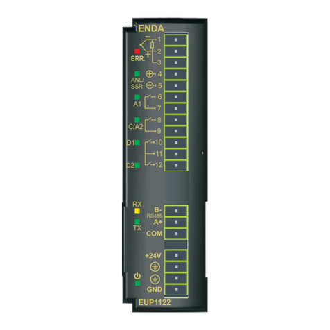
E-T-A Control Plex CPC10PB-T1 User manual

Busklemmen-Controller / Bus Controller
CPC10PB-T1 / -T4
Installationsanleitung / Installation Manual

X61 USB-Serviceschnittstelle zur Verbindung mit der
Bedienoberfläche ControlPlex®Views
Leitungslänge: max. 2 m
Typ: USB-2.0 Typ B
X61 USB service interface for connection of user
interface ControlPlex®Views
Cable length: max. 2 m
Type: USB-2.0 Type B
X51/ X52 / X53 /X54 ELBus® connectors for
SVS201-PWR-xx
Cable length: max. 2 m
Typically: H07V-K 1,5 mm²
Connector 1: ELBus®ELB Data line
Female connector 2: ELBus® DC + 24 V
Female connector 3: ELBus® GND
X51/ X52 / X53 /X54 ELBus®-Anschlüsse für
SVS201-PWR-xx
Leitungslänge: max. 2 m
Typischerweise: H07V-K 1,5 mm²
Buchse 1: ELBus®ELB Datenleitung
Buchse 2: ELBus® DC + 24 V
Buchse 3: ELBus® GND
1. Datenleitung ELBus®
2. Versorgungsspannung ELBus® + 24 V
3. Versorgungsspannung ELBus® GND
1. Data line ELBus® ELB
2. Supply voltage ELBus® + 24 V
3. Supply voltage ELBus® GND
Buchse X51/X52/X53/X54 CPC10 Connector X51/X52/X53/X54 CPC10X50-COM SVS201-PWR X50-COM SVS201-PWR
X41 voltage supply
Rated voltage: DC 24 V (18...32 V), ground
symmetrical rail (PE/FE)
Rated current: typically = 60 mA
cable cross section max. 2.5 mm2
X41 Spannungsversorgung
Nennspan-
nung:
DC 24 V (18...32 V) Tragschiene erden
(PE/FE)
Nennstrom: typ. = 60 mA
Anschlussvermögen
(Leiterquerschnitt)
max. 2,5 mm2
Safety Indication
Non-observance of the technical data can cause considerable da-
mage of the device and the entire system. E-T-A is unable to accept
responsibility for customer or third party liability, warranty claims or
damage caused by incorrect installation or improper handling in dis-
regard of the technical data.
Sicherheitshinweis
Eine Nichtbeachtung der technischen Daten kann zu erheblichen
Schäden am Gerät und an der Anlage führen. E-T-A übernimmt ge-
genüber dem Kunden oder Dritten keine Haftung, Gewährleistung
oder Garantie für Mängel oder Schäden, die durch fehlerhaften Ein-
bau oder unsachgemäße Handhabung unter Nichtbeachtung der
technischen Daten verursacht wurde.
Busklemmen-Controller
CPC10PB-T1
X81
Busschnittstelle
PROFIBUS-DP
Adressier-Drehschalter
X61
USB-
Serviceschnittstelle
LED PWR
CPC
10PB
-T1
COM-1
CPC10PB-T4
COM-2
COM-3
COM-4
X51
X52
X53
X54
X61 X81 X51/COM-1
NS
MS
CM
CE
DC
24 V
X41PWR
X61 X81
NS
MS
CM
CE
DC
24 V
X41PWR
Busklemmen-Controller
CPC10PB-T4
+ +0V 0 V
+ + 0 V 0 V X41
Spannungsversorgung
DC 24 V
LED NS
LED MS
LED CM
LED CE
X51, X52,
X53, X54
ELBus®-
Anschlüsse
Bus Controller
CPC10PB-T1
X81
bus interface
PROFIBUS-DP
Address rotary switch
X61
USB service interface
LED PWR
CPC
10PB
-T1
COM-1
CPC10PB-T4
COM-2
COM-3
COM-4
X51
X52
X53
X54
X61 X81 X51/COM-1
NS
MS
CM
CE
DC
24 V
X41PWR
X61 X81
NS
MS
CM
CE
DC
24 V
X41PWR
Bus Controller
CPC10PB-T4
+ +0V 0 V
+ + 0 V 0 V X41
voltage supply DC 24 V
LED NS
LED MS
LED CM
LED CE
X51, X52,
X53, X54
ELBus®-
connectors
LED indication and connectionAnzeige und Anschlusselemente

LED MS: Die Leuchtdiode MS zeigt den Status des internen Busschnitt-
stellen-Kommunikationsmoduls an. Nähere Informationen entnehmen
sie bitte dem Benutzerhandbuch.
LED NS: Die Leuchtdiode NS zeigt den Netzwerkstatus der Kommu-
nikation des internen Busschnittstellen-Kommunikationsmoduls zum
Master des Bussystems an. Nähere Informationen entnehmen sie bitte
dem Benutzerhandbuch.
Hinweis: Ausführliche Handbücher, Produktdatenblätter, Software-
tools sowie gerätespezifische Gerätedateien (GSD-Dateien) sind auf
der E-T-A Homepage zum Download bereitgestellt. Stellen Sie si-
cher, dass Sie immer mit den aktuellen Dokumenten arbeiten.
Note: Detailed user manuals, data sheets, software tools and pro-
duct-specific files are availabe on the E-T-Ahomepage for download.
Please make sure to always use the most recent documents.
LED MS: The LED MS shows the status of the internal bus interface
communication module. For further details please see user manual.
LED NS: The LED NS shows the network status of the communication of
the internal bus interface communication module to the master of the bus
system. For further details please see user manual.
Betriebsart Signalisierung der Betriebsart
LED CM LED CE LED PWR
Startup Mode gelb gelb grün
System Error Mode gelb rot grün
Configuration Error Mode gelb rot/aus* grün
Standalone Mode gelb - grün
Slave Mode grün rot grün
Frimewareupdate rot/aus* rot/aus* rot/aus*
Operating mode Indication of operating mode
LED CM LED CE LED PWR
Startup Mode yellow yellow green
System Error Mode yellow red green
Configuration Error Mode yellow red/off* green
Standalone Mode yellow - green
Slave Mode green red green
Frimewareupdate red/off* red/off* red/off*
Power Distribution board 1
ELBus®
ELBus®
ELBus®
ELBus®
Power Distribution board 2
Power Distribution board 3
Power Distribution board 4
COM-1
CPC10PB-T4
COM-2
COM-3
COM-4
X51
X52
X53
X54
X61X81
NS
MS
CM
CE
DC
24 V
X41PWR
+ +0V 0 V
GE R M A N Y
Typ:SVS201-PWR-16-001
DC24V/40A X31
1+ 2+ 1- 2- PE
X50
COM
F1 F2 F3 F4 F5 F6 F7 F8 F9 F10 F11 F12 F13 F14 F15 F16
X1 X2 X3 X4 X5 X6 X7 X8 X9 X10 X11 X12 X13 X14 X15 X16
1+ 2+ 1+ 2+ 1+ 2+ 1+ 2+ 1+ 2+ 1+ 2+ 1+ 2+ 1+ 2+ 1+ 2+ 1+ 2+ 1+ 2+ 1+ 2+ 1+ 2+ 1+ 2+ 1+ 2+ 1+ 2+
1- 2- 1- 2- 1- 2- 1- 2- 1- 2- 1- 2- 1- 2- 1- 2- 1- 2- 1- 2- 1- 2- 1- 2- 1- 2- 1- 2- 1- 2- 1- 2-
1/ELB
2/+24V
3/GND
Madein Germany
SVS201-PWR
CPC10PB-T4*
bus interface
PROFIBUS-DP
USB maintance
and service interface
Electronic circuit protector
ESX50D-S1-xxx plug-in type
*Only one power distribution board can be
connectet when using a CPC10PB-T1
PLC
ControlPlex®Tools
Service laptop
ControlPlex®Views
on
off
IN
/
A
ESX50D
-S110-
DC24V
r
e
s
e
t
Stromverteiler 1
ELBus®
ELBus®
ELBus®
ELBus®
Stromverteiler 2
Stromverteiler 3
Stromverteiler 4
COM-1
CPC10PB-T4
COM-2
COM-3
COM-4
X51
X52
X53
X54
X61X81
NS
MS
CM
CE
DC
24 V
X41PWR
+ +0V 0 V
GE R M A N Y
Typ:SVS201-PWR-16-001
DC24V/40A X31
1+ 2+ 1- 2- PE
X50
COM
F1 F2 F3 F4 F5 F6 F7 F8 F9 F10 F11 F12 F13 F14 F15 F16
X1 X2 X3 X4 X5 X6 X7 X8 X9 X10 X11 X12 X13 X14 X15 X16
1+ 2+ 1+ 2+ 1+ 2+ 1+ 2+ 1+ 2+ 1+ 2+ 1+ 2+ 1+ 2+ 1+ 2+ 1+ 2+ 1+ 2+ 1+ 2+ 1+ 2+ 1+ 2+ 1+ 2+ 1+ 2+
1- 2- 1- 2- 1- 2- 1- 2- 1- 2- 1- 2- 1- 2- 1- 2- 1- 2- 1- 2- 1- 2- 1- 2- 1- 2- 1- 2- 1- 2- 1- 2-
1/ELB
2/+24V
3/GND
Madein Germany
GE R M A N Y
Typ:SVS201-PWR-16-001
DC24V/40A X31
1+ 2+ 1- 2- PE
X50
COM
F1 F2 F3 F4 F5 F6 F7 F8 F9 F10 F11 F12 F13 F14 F15 F16
X1 X2 X3 X4 X5 X6 X7 X8 X9 X10 X11 X12 X13 X14 X15 X16
1+ 2+ 1+ 2+ 1+ 2+ 1+ 2+ 1+ 2+ 1+ 2+ 1+ 2+ 1+ 2+ 1+ 2+ 1+ 2+ 1+ 2+ 1+ 2+ 1+ 2+ 1+ 2+ 1+ 2+ 1+ 2+
1- 2- 1- 2- 1- 2- 1- 2- 1- 2- 1- 2- 1- 2- 1- 2- 1- 2- 1- 2- 1- 2- 1- 2- 1- 2- 1- 2- 1- 2- 1- 2-
1/ELB
2/+24V
3/GND
Madein Germany
GE R M A N Y
Typ:SVS201-PWR-16-001
DC24V/40A X31
1+ 2+ 1- 2- PE
X50
COM
F1 F2 F3 F4 F5 F6 F7 F8 F9 F10 F11 F12 F13 F14 F15 F16
X1 X2 X3 X4 X5 X6 X7 X8 X9 X10 X11 X12 X13 X14 X15 X16
1+ 2+ 1+ 2+ 1+ 2+ 1+ 2+ 1+ 2+ 1+ 2+ 1+ 2+ 1+ 2+ 1+ 2+ 1+ 2+ 1+ 2+ 1+ 2+ 1+ 2+ 1+ 2+ 1+ 2+ 1+ 2+
1- 2- 1- 2- 1- 2- 1- 2- 1- 2- 1- 2- 1- 2- 1- 2- 1- 2- 1- 2- 1- 2- 1- 2- 1- 2- 1- 2- 1- 2- 1- 2-
1/ELB
2/+24V
3/GND
Madein Germany
GE R M A N Y
Typ:SVS201-PWR-16-001
DC24V/40A X31
1+ 2+ 1- 2- PE
X50
COM
F1 F2 F3 F4 F5 F6 F7 F8 F9 F10 F11 F12 F13 F14 F15 F16
X1 X2 X3 X4 X5 X6 X7 X8 X9 X10 X11 X12 X13 X14 X15 X16
1+ 2+ 1+ 2+ 1+ 2+ 1+ 2+ 1+ 2+ 1+ 2+ 1+ 2+ 1+ 2+ 1+ 2+ 1+ 2+ 1+ 2+ 1+ 2+ 1+ 2+ 1+ 2+ 1+ 2+ 1+ 2+
1- 2- 1- 2- 1- 2- 1- 2- 1- 2- 1- 2- 1- 2- 1- 2- 1- 2- 1- 2- 1- 2- 1- 2- 1- 2- 1- 2- 1- 2- 1- 2-
1/ELB
2/+24V
3/GND
Madein Germany
SVS201-PWR
CPC10PB-T4*
Bus-Schnittstelle
PROFIBUS-DP
USB Wartungs- und
Service-Schnittstelle
Elektronischer
Sicherungsautomat
ESX50D-S1xx steckbar
*Bei der Verwendung eines CPC10PB-T1 kann
nur 1 Stromverteiler angeschlossen werden.
Steuerung
ControlPlex®Tools
Service Laptop
ControlPlex®Views
on
off
IN
/
A
ESX50D
-S110-
DC24V
r
e
s
e
t
* blinkend
* flashing
System Overview
ControlPlex®
Systemübersicht
ControlPlex®
X81 PROFIBUS-DP-Schnittstelle (beim Gerät CPC10PB-Tx)
Typ: Buchse 9-polig SUB-D
Bei der Verdrahtung und dem Anschluss an das Bussystem PRO-
FIBUS-DP sind die Installations- und Verdrahtungsvorschriften der
PROFIBUS Nutzerorganisation e.V. (PNO) einzuhalten.
X81 PROFIBUS-DP interface (for unit CPC10PB-Tx)
Type: Connector 9-pole SUB-D
When wiring and connecting to the bus system PROFIBUS-DP the in-
stallation and wiring regulations of the PROFIBUS User Organisation
(PNO) have to be observed.
LED CM: Die Leuchtdiode CM zeigt den Status der Kommunikation
zwischen der Kommunikationseinheit und den elektronischen Siche-
rungsautomaten an.
LED CE: Die Leuchtdiode CE zeigt den Status der Kommunikations-
einheit an.
LED PWR: Bei angelegter Versorgungsspannung leuchtet die Diode
PWR grün.
LED CM: The LED CM shows the status of the communication between
the communication unit and electronic circuit protector.
LED CE: The LED CE shows the status of the communication unit.
LED PWR: The PWR diode lights up green if voltage is applied.

http://www.e-t-a.de/qr1014
Installationsanleitung / Installation Manual CPC10PB-T1 /-T4 (D,E)
Bestell-Nr. / Ref. number Y31179301 - Index: a
Ausgabe / Issue: 01/2015 / Alle Rechte vorbehalten / All rights reserved
E-T-A Elektrotechnische Apparate GmbH
Industriestraße 2-8 .90518 ALTDORF
GERMANY
Tel. 09187 10-0 .Fax 09187 10-397
This manual suits for next models
1
Other E-T-A Controllers manuals
E-T-A
E-T-A ControlPlex CPC20PN User manual
E-T-A
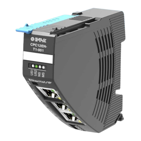
E-T-A EtherNetIP ControlPlex CPC12EN User manual
E-T-A
E-T-A E-1071-623 User manual
E-T-A
E-T-A ControlPlex CPC10PB User manual
E-T-A
E-T-A EM12D-TMB Series User manual
E-T-A
E-T-A ControlPlex CPC12 User manual

E-T-A
E-T-A ControlPlex CPC12 User manual
E-T-A
E-T-A ControlPlex CPC12 T Series User manual
E-T-A
E-T-A EtherNetIP ControlPlex CPC12EN User manual
E-T-A
E-T-A ControlPlex CPC12 T Series User manual
