VMT VMT10 Series User manual
WICHTIG:
Wir weisen ausdrücklich darauf hin, dass Brems- und Kupplungsteile sicher-
heitsrelevante Fahrzeugteile sind. Daher dürfen erforderliche Arbeiten nur
von entsprechend qualizierten Personen durchgeführt werden.
Lesen Sie diese Montageanleitung in Ruhe bis zum Ende durch, bevor mit den
Arbeiten begonnen wird. Diese Montageanleitung dient nur als Richtlinie und
ist nicht für einen bestimmten Motorradtyp erstellt.
Für Fahrzeugspezische Anleitungen, Entlüftungsvorschriften und Anweisun-
gen richten Sie sich jeweils nach dem Werkstatthandbuch des Fahrzeugher-
stellers oder fragen Ihren Fachhändler.
Hinweis:
Dieser universelle Bremsleitungs- und Kupplungsleitungs Verlängerungsad-
apter ist zur Verwendung an Fahrzeugen mit einer Gewindesteigung von
M10x1.0 M10x1.25 und 3/8“UNF-24 geeignet.
IMPORTANT:
Rider and passenger safety depend upon the correct installation of this kit.
Use the appropriate service manual procedures. If the procedure is not within
your capabilities or you do not have the correct tool, have a certied
professional perform the installation. Impropper installation of this kit could
result in death or serious injury.
Please read these assembly instructions carefully to the end before starting
any work. These assembly instructions are only intended as a guideline and
have not been prepared for a specic type of motorcycle.
For vehicle-specic instructions, venting instructions and directives, refer to
the vehicle manufacturer’s workshop manual or ask your specialist dealer.
Note:
This universal brake line and clutch line extension adapter is designed for use
on vehicles with a thread pitch of M10x1.0,M10x1.25 and 38“UNF-24.
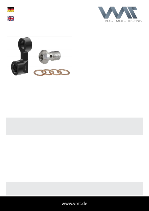
Lieferumfang:
•1x Adapter
•1x Hohlschraube V2A Torx
•4x Kupferdichtringe
Delivery of contents:
•1x adapter
•1x banjo bolt V2A Torx
•4x copper sealing rings
VMT10x1U
VMT10x1U
04/2022
Montageanleitung
3cm Brems- und Kupplungsleitungs-Verlängerung universal (Radial)
3cm extension for brake hoses and cluth hoses for motorcycles (radial)

Demontage
Lösen Sie den Brems- bzw. Kupplungsschlauch an der zu verlängerden Stelle.
ACHTUNG: Hierbei entweicht etwas Bremsüssigkeit (bzw. je nach System Mine-
ralöl). Fangen Sie diese ab, so dass keine Komponenten des Fahrzeugs in Verbin-
dung mit der Flüssigkeit kommen. Es können Lackschäden entstehen!
Solange das System geönet ist, darf der Brems- und Kupplungshebel nicht beschä-
digt werden! Sollte das dennoch passieren, muss das Brems- bzw. Kupplungssystem
komplett entlüftet werden. Gehen Sie hierbei nach Fahrzeughandbuch vor oder besu-
chen Sie eine Fachwerkstatt.
Montage
Montieren Sie den Adapter (4) mit der originalen Hohlschraube
(1) (nicht im Lieferumfang)an dem Brems- bzw. Kupplungs-
zylinder, der Bremszange, oder an Verteilern (Anzugsdrehmo-
ment nach Fahrzeughandbuch!). Die beiliegenden Dichtringe
(5) werden zwischen den Bauteilen verwendet. Anschließend
wird der originale Brems- bzw. Kupplungsschlauch (3)
mit der beiligenden Hohlschraube (2) befestigt (An-
zugsdrehmoment 18-23Nm). Nutzen Sie hierfür die
beiliegenden Dichtringe.
In vielen Fällen ist eine Entlüftung des Hydrauliksys-
tems nicht notwendig (bei der Montage an Geberzy-
lindern). Betätigen Sie den Hebel mehrmals (min. 3
Minuten lang). Sollte der Systemdruck nicht herge-
stellt worden sein, spannen Sie den Bremshebel bzw.
Kupplungshebel über Nacht unter Druck an den Lenker.
Anschließend funktioniert das System wieder normal.
In Einzelfällen kann eine Entlüftung des Systems erfor-
derlich werden. Wird der Adapter an anderer Stelle ei-
nes Bremssystems oder Kupplungssystems eingesetzt,
ist eine Entlüftung des Systems generell notwendig.
Bei Radialzylindern mit untenliegendem Ausgang ist
eine Montage ohne Entlüftung erschwert.
Kontrolle
Kontrollieren Sie den Mindestüssigkeitsstand am Fenster des Ausgleichsbehälters
und füllen Sie ggf. nach Fahrzeughandbuch nach. Entfernen Sie restliche Flüssigkei-
ten an der Außenseite der Bauteile und prüfen Sie die Dichtigkeit der Verbindungen.
Vor der ersten Fahrt muss in Schrittgeschwindigkeit eine Bremsprüfung erfolgen.
Die Arbeiten sind nun abgeschlossen! Eine regelmäßige Prüfung des festen Sitzes
und der Dichtigkeit der Bauteile muss jedoch gewährleitet sein. Sollte ein Bauteil
Beschädigungen aufweisen, muss dieses umgehend ersetzt werden.
Hinweis:
• Bitte verwenden Sie nur geeignetes Werkzeug
• Achten Sie auf einen sicheren Halt des Motorrads während der Arbeiten
• Führen Sie die Montage in sauberen und nicht staubenden Bereichen durch
• Eine zweite Person zur Hilfe erleichtert die Montage erheblich
Vielen Dank, dass Sie sich für ein Qualitätsprodukt
der VOIGT MOTO TECHNIK entschieden haben.

Disassembly
Disconnect the brake or clutch line at the point to be extended.
ATTENTION: This causes some brake uid (or mineral oil, depending on the
system)to leak out. Prevent this from coming into contact with any components of
the vehicle. Damage to the paintwork may result!
As long as the system is open, the brake and clutch lever must not be damaged!
If this should however happen, the brake or clutch system must be completely re-
vented. Proceed according to the vehicle manual or visit a specialist workshop.
Assembly
Mount the adapter (4) with the original banjo bolt (1) (not
included)on the brake or clutch cylinder, the brake caliper, or
on splitters (torque as specied in the vehicle manual!).
The enclosed sealing rings (5) are used between the
components. Then fasten the original brake or clutch hose (3)
with the enclosed banjo bolt (2) (torque 18-23Nm).
Use the enclosed sealing rings here as well.
In most cases, it is not necessary to bleed the hydraulic
system (when mounting on the hand master
cylinders). Operate the lever several times (for at
least 3 minutes). If the system pressure has not been
established, clamp the brake lever or clutch lever to
the handlebar under pressure overnight. The system
will then function properly again. In individual cases, it
may be necessary to bleed the system. If the adapter
is used elsewhere in a brake or clutch system, bleeding
of the system is generally necessary. In the case of
radial cylinders with a bottom outlet, installation
without bleeding is more dicult.
Inspection
Check the minimum uid level at the window of the uid container and top up
according to the vehicle manual if necessary. Remove any remaining uid from the
outside of the components and check the tightness of the connections. Before the
rst ride, a brake test must be carried out at walking speed.
The work is now complete! However, a regular check of the secure t and the
tightness of the components must be ensured. If a component is damaged, it must
be replaced immediately.
Note:
• Please make sure to only use suitable tools
• Make sure that the motorcycle is secured safely
• Carry out the installation in clean and dust-free areas
• A second person to help out considerably eases the installation
Thank you for choosing a quality product
from VOIGT MOTO TECHNIK GmbH.

VOIGT MOTO TECHNIK
Table of contents
Languages:
Other VMT Motorcycle Accessories manuals


