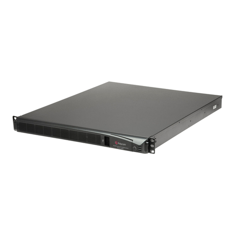
Vocord Avantpost VB4 User manual

User’s guide
Compact server
for video surveillance systems
VOCORD Avantpost
VB4/VB8
Date of issue: April, 2009


Table of Contents
Introduction ................................................................................................................................................ 7
1. User Guide Contents ......................................................................................................................... 8
2. Typographical Conventions ................................................................................................................ 9
2.1. Special Elements .................................................................................................................... 9
2.2. Abbreviations ........................................................................................................................ 9
2.3. Terms ................................................................................................................................... 9
3. Send Us Your Comments ................................................................................................................. 10
1. General Information ............................................................................................................................... 11
1.1. Device Application Areas .............................................................................................................. 11
1.2. Performance Capabilities, Technical Specifications ........................................................................... 11
1.3. Device Models ............................................................................................................................ 13
1.4. Package Contents ........................................................................................................................ 14
1.5. Minimum Hardware and Software Requirements ............................................................................ 14
1.6. Storage and Operating Conditions. Reliability Characteristics ............................................................ 15
1.7. Safety Requirements .................................................................................................................... 15
2. Video Server Operation Description .......................................................................................................... 17
2.1. Recording Modes ........................................................................................................................ 18
2.2. Alarm Sensor Triggering Modes .................................................................................................... 19
2.3. Motion Detector: General Information ........................................................................................... 21
2.4. Maximum Frame Rate .................................................................................................................. 22
2.5. Streaming Video Viewing Modes ................................................................................................... 23
2.6. Web Interface ............................................................................................................................. 23
2.7. OWS Software ............................................................................................................................. 24
2.8. Configuring the Device Network Settings ....................................................................................... 24
2.9. Data Exchange Between Video Server and OWS ............................................................................. 25
2.10. Hard Drive. Archive Structure. Video Record Size ........................................................................... 25
2.11. PTZ Video Camera Control .......................................................................................................... 26
2.12. Authorization System. Login and Password ................................................................................... 27
3. Hardware Installation .............................................................................................................................. 29
3.1. Device Installation ....................................................................................................................... 30
3.2. Signal Sources and Connection Cables ........................................................................................... 31
3.3. Connectors ................................................................................................................................. 31
3.3.1. Unused Connectors, Ports and Indicators ............................................................................ 31
3.3.2. Video Inputs .................................................................................................................... 32
3.3.3. Audio Inputs .................................................................................................................... 32
3.3.4. Ethernet (LAN) Connector ................................................................................................. 33
3.3.5. Alarm Inputs Connector .................................................................................................... 33
3.3.6. Power Connector .............................................................................................................. 34
3.3.7. RS232/485 Connector ..................................................................................................... 34
3.4. Video Output .............................................................................................................................. 35
3.5. Switches ..................................................................................................................................... 36
3.6. Indicators ................................................................................................................................... 38
4. OWS Software Installation and Uninstallation ............................................................................................ 39
4.1. Software Installation .................................................................................................................... 39
4.2. Software Uninstallation ................................................................................................................ 42
4.2.1. Using the setup_Tahion.Avantpost.exe Application .............................................................. 42
5. Initial Configuration ................................................................................................................................ 45
5.1. Web Browser Configuration .......................................................................................................... 45
5.2. IP Packet Filtering Permissions ....................................................................................................... 48
5.3. Locating the Device in the Network ............................................................................................... 49
5.4. Configuring the Device ................................................................................................................. 49
5.5. Enabling Hardware Acceleration ................................................................................................... 49
5.6. Ports Used by the Device and OWS ................................................................................................ 52
6. Web Interface ........................................................................................................................................ 53
6.1. Running the Web Interface ........................................................................................................... 53
6.2. Web Interface Design Principles .................................................................................................... 54

6.3. Screen Forms Layout .................................................................................................................... 54
6.3.1. Control Panel ................................................................................................................... 55
6.3.2. User Menu ...................................................................................................................... 56
6.4. Monitor ...................................................................................................................................... 56
6.4.1. Monitoring mode ............................................................................................................. 57
6.4.2. Step-frame mode ............................................................................................................. 61
6.5. Archive ....................................................................................................................................... 62
6.5.1. Archive Records Table ....................................................................................................... 63
6.5.2. Download Exported Files ................................................................................................... 65
6.6. Settings ...................................................................................................................................... 66
6.6.1. General Settings ............................................................................................................... 66
6.6.2. Audio Channels ................................................................................................................ 68
6.6.3. Video Channels ................................................................................................................ 68
6.6.4. Video Channel N .............................................................................................................. 69
6.6.5. Sensors ........................................................................................................................... 72
6.6.6. Motion Detectors ............................................................................................................. 73
6.6.7. RS-232/422/485 Control Interface .................................................................................. 75
6.7. Administration ............................................................................................................................ 76
6.7.1. Users .............................................................................................................................. 77
6.7.2. Settings Import ................................................................................................................ 79
6.7.3. Settings Export ................................................................................................................. 81
6.7.4. Date and Time .................................................................................................................. 82
6.7.5. Network .......................................................................................................................... 83
6.7.6. Diagnostics ...................................................................................................................... 88
6.7.7. System mode ................................................................................................................... 90
6.7.8. Embedded Software Updating ........................................................................................... 91
6.8. Situations When User Action is Required ........................................................................................ 93
7. Tahion.NetView Utility ............................................................................................................................. 95
7.1. Starting the Utility ........................................................................................................................ 95
7.2. Main Window ............................................................................................................................. 95
7.2.1. Workspace Area ............................................................................................................... 96
7.2.2. Menu .............................................................................................................................. 98
7.2.3. Toolbar ............................................................................................................................ 99
7.2.4. Main Window Advanced View ........................................................................................... 99
7.2.5. Context Menu ................................................................................................................ 100
7.2.6. Device Filtering ............................................................................................................... 101
7.3. Tooltip Menu ............................................................................................................................ 102
7.4. Message Windows .................................................................................................................... 102
8. Tahion.Avantpost Application ................................................................................................................ 105
8.1. Starting the Utility ...................................................................................................................... 105
8.2. Main Window ........................................................................................................................... 106
8.3. “Monitor”Mode ....................................................................................................................... 107
8.4. “Archive”Mode ......................................................................................................................... 108
8.4.1. Playback Block ............................................................................................................... 109
8.4.2. Archive Records Table ..................................................................................................... 110
8.5. Settings Window ....................................................................................................................... 112
8.5.1. Settings Tree .................................................................................................................. 114
8.5.2. Parameters Panel (Image Settings) ................................................................................... 114
8.5.3. Parameters Panel (Video Export Settings) .......................................................................... 119
9. Tahion.Tunnel Utility ............................................................................................................................. 121
9.1. Starting the Utility ...................................................................................................................... 121
9.2. Main Window ........................................................................................................................... 121
10. VocordErrorReportTool Utility ............................................................................................................... 125
11. Recommended Operating Guidelines .................................................................................................... 127
11.1. General Video Server Operating Guidelines ................................................................................ 127
11.1.1. General Instructions ...................................................................................................... 127
11.1.2. Connection Status Check and User Notification ................................................................ 127
11.1.3. Resolving the New Device IP Address .............................................................................. 128
4
VOCORD AVANTPOST VB4/VB8

11.1.4. Maintenance Recommendations .................................................................................... 128
11.1.5. Audio Recording Recommendations ............................................................................... 129
11.1.6. Turning the Device Off .................................................................................................. 129
11.1.7. If the Battery Has Run Out ............................................................................................. 130
11.2. Device Administration .............................................................................................................. 130
11.2.1. Importing/Exporting Device Settings .............................................................................. 130
11.2.2. Device Diagnostics ........................................................................................................ 130
11.3. Configuring the Device ............................................................................................................. 135
11.3.1. Compression Settings .................................................................................................... 135
11.3.2. Motion Detector Setup .................................................................................................. 136
11.4. Using the Tahion.NetView Utility ............................................................................................... 138
11.4.1. Scanning Network for Devices ....................................................................................... 139
11.4.2. Viewing Device Information ........................................................................................... 139
11.4.3. Editing Channel Name .................................................................................................. 139
11.4.4. Switching Off/On the Connection Status Monitoring for Selected Device ............................ 139
11.4.5. Deleting Device from the List ......................................................................................... 139
11.4.6. Removing Device from the Configuration (Configuration File) ........................................... 140
11.4.7. Saving the Configuration (Configuration File) to OWS Hard Drive ...................................... 140
11.4.8. Enabling/Disabling Tooltips ........................................................................................... 140
11.4.9. Enabling/Disabling Configuration Autosave .................................................................... 140
11.4.10. Enabling/Disabling Logging ........................................................................................ 141
11.4.11. Changing the Log File Maximum Size ........................................................................... 141
11.5. Working with the Tahion.Avantpost Application .......................................................................... 141
11.5.1. Working with the Archive of a VOCORD Avantpost Device ................................................ 141
11.5.2. Audio Playback ............................................................................................................ 142
11.6. Establishing Connection Using the Tahion.Tunnel Utility ............................................................... 143
12. Troubleshooting Recommendations ...................................................................................................... 145
12.1. Troubleshooting ...................................................................................................................... 145
12.2. Connecting the Device with Crossover Cable .............................................................................. 149
12.2.1. Recommendations for Making a Crossover Cable ............................................................. 150
12.2.2. Device Network Settings Check ...................................................................................... 150
12.2.3. Configuring the OWS Network Settings .......................................................................... 151
12.2.4. Configuring the Device Network Settings ........................................................................ 154
13. Settings Examples ............................................................................................................................... 155
13.1. Continuous Recording .............................................................................................................. 155
13.2. Alarm Triggered Recording ....................................................................................................... 156
13.3. Combined Continuous Recording and Alarm Triggered Recording ................................................. 157
Glossary .................................................................................................................................................. 159
© V
© Voc
ocor
ord T
d Telec
elecom
om5
VOCORD AVANTPOST VB4/VB8


Introduction
Video surveillance systems have become an integral part of modern security systems. The Vocord company presents
a modern solution for extending video surveillance systems capabilities —the video server1VOCORD Avantpost VB4
(VOCORD Avantpost VB8).
The VOCORD Avantpost VB4 and VOCORD Avantpost VB8 device models have similar technical specifications and
are software-compatible. The 8-channel VOCORD Avantpost VB8 device model has more channels for connecting
video cameras and slightly broader functionality than the 4-channel VOCORD Avantpost VB4. For more detailed de-
scription of device models refer to Device Models.
The VOCORD Avantpost video server can be used as a stand-alone recording device. In the stand-alone mode, the
audio and video data are recorded to a removable hard drive. You can control the device and access streaming or re-
corded video and audio data via Local Area Network or Internet.
The video server can also operate as a remote device in a distributed video surveillance system. In this case the video
and audio data are recorded at the recording station.
The description of video server as a remote device is beyond the scope of this User Guide.
VOCORD Avantpost features:
•compact size;
•operation under extreme conditions;
•low power consumption;
•high-quality synchronous video and audio recording;
•user-friendly Web interface for operating the device. You can control the video server from any PC with a Web
browser installed.
The device has all the necessary video processing and transmitting capabilities. Depending on the number of connected
cameras, video resolution and network bandwidth, up to 50 fps of PAL format video data can be transferred (total
for all video channels). The device performs the analogue-to-digital conversion and compression of data coming from
one or several video cameras. The integrated Web server allows operating the device and transmitting the video stream
(monitoring channel signal) over the LAN or Internet.
VOCORD Avantpost can be used as part of an analogue video surveillance system for transmitting the video signal
from 1 to 8 analogue cameras over the network or recording it to a hard drive. VOCORD Avantpost can be integrated
into video surveillance systems at shops, airports, passenger terminals, banks, large office areas, kindergartens and
etc. The video surveillance system operator or responsible company staff can monitor the video signal coming to the
video server through the Local Area Network or Internet.
The device features 4 external alarm sensor inputs, a built-in motion detector, an alarm relay output and prerecording
function. Video recording may be initiated by triggering an alarm sensor or a motion detector, which allows tracking
and analysing events that happened after the alarm triggering.
VOCORD Avantpost has a RS-232/422/485 control interface. It allows operators to control a PTZ camera while
viewing the monitoring channel video.
1Hereinafter the VOCORD Avantpost VB4 (VOCORD Avantpost VB8) video server will also be referred to as VOCORD Avantpost, “the video server”
or “the device”.

The device is intended for use by the following organizations:
•security services;
•dispatching desks and emergency services;
•call processing centers;
•airway, energy, and industrial companies;
•financial companies (banks, exchanges, brokerage companies).
This User Guide contains the device and software description. All information on device installation and usage is
contained in one document.
The User Guide is intended for experienced users.
1. User Guide Contents
The document contains the following chapters:
Describes document structure and device features.Introduction
Describes the purpose of the device, its application areas,
functional capabilities, hardware and software require-
ments, operating conditions, and device design.
General Information
Describes various aspects concerning viewing and record-
ing video with the device.
Video Server Operation Description
Provides information on assembling, signal sources, cables,
connectors, switches, and indicators of the device.
Hardware Installation
Describes operator workstation software installation and
uninstallation procedure.
OWS Software Installation and Uninstallation
Describes the configuration following the hardware and
software installation.
Initial Configuration
Describes the Web interface of the device.Web Interface
Describes the Tahion.NetView utility.Tahion.NetView Utility
Describes the Tahion.Avantpost application.Tahion.Avantpost Application
Describes the Tahion.Tunnel utility.Tahion.Tunnel Utility
Describes the VocordErrorReportTool utility.VocordErrorReportTool Utility
Describes standard operating guidelines and details of
specific operations.
Recommended Operating Guidelines
Describes possible operation problems and solutions.Troubleshooting Recommendations
Provides examples of video channel settings for the device.Settings Examples
Provides definitions of the terms used in this User Guide.Glossary
The User Guide can be read consecutively or used as a reference source. If this is your first time reading the User Guide,
we recommend reading it in consecutive order. For obtaining only essential information about device and software
installation and initial configuration refer to sections: General Information, Hardware Installation, Software Installation,
and Initial Configuration. The sections mentioned above also contain references to other sections of this User Guide.
8
INTRODUCTION

2. Typographical Conventions
Fonts and formatting used in the document for various terms and titles:
DescriptionFont, formatting
Used for utility and application titles, screen forms, win-
dows and window elements, and keyboard keys.
Bold
Used for document titles and references to terms.Italic
2.1. Special Elements
Note –provides additional information on the subject. A Note can precede a chapter, section, subsection, figure or
immediately follow the related element.
Caution –attracts attention to important information. Directions and notes marked with this element should be strictly
followed to ensure reliable operation of hardware and software and to avoid data losses.
Object names, basic operation names and field values are put in double quotation marks. Numeric literals used without
units of measurement are put in angle brackets.
2.2. Abbreviations
The following abbreviations are used in this User Guide:
DescriptionAbbreviation
Screen formSF
Operator workstationOWS
The following abbreviations are used to specify time and date:
•DD - day of a month;
•MM - month;
•YYYY - year;
•hh - hours;
•mm - minutes;
•ss - seconds;
•ms - milliseconds.
2.3. Terms
The following terms are used in this User Guide:
© V
© Voc
ocor
ord T
d Telec
elecom
om9
INTRODUCTION

DescriptionTerm
Move the mouse pointer to an object (field, button, etc.),
then quickly press and release the mouse button. Use the
left mouse button by default.
Click
Type a text or a number using keyboard.Type
Select and run a menu command or click a command but-
ton in a dialogue box.
Select
Quickly press and release a mouse button twice.Double-click
Press a keyboard button.Press
Move the mouse pointer to an object, press the mouse
button and move the object without releasing the mouse
button.
Drag
3. Send Us Your Comments
Please let us know if you have any comments or suggestions on how to enhance the quality and contents of this
document. Please send your comments to the Vocord company in the following cases:
•you find mistakes in the text;
•information is incomplete;
•you need additional explanation and examples for better understanding of the subject;
•any merits of this document should be maintained and developed in the following versions.
Please send us your feedback and proposals using one of the following ways:
•Fax: +7 (495) 787-2626
•Request/question form found at our Web sites: www.vocord.ru, www.vocord.com, www.vocord.net
•E-mail: support@vocord.com [mailto:support@vocord.com]
•Mailing address: VOCORD Company, P.O. Box 7, 123298 Moscow, Russia
10
INTRODUCTION

CHAPTER 1. GENERAL INFORMATION
1.1. Device Application Areas
The chapter contains information about device application areas, performance capabilities, design, conditions of use,
safety requirements, package contents, minimum PC hardware and software requirements.
Video server VOCORD Avantpost is intended to work as a part of a video surveillance system, to perform analogue-
to-digital video and audio signal conversion and transfer converted data via computer network or record data to a
hard drive.
The video server is resistant to low temperatures. While the video server is turned off, its temperature decreases to
the environment level. To ensure high power-up speed of the device in such conditions, there is a built-in automatic
warm-up and temperature control system.
The device application areas:
•company and government automobile vehicles, including police vehicles on duty;
•public vehicles, school buses;
•counterterrorism systems for rail transport and underground railway;
•stand-alone video recording systems in local government offices or unguarded sites, such as: schools, hospitals,
kindergartens, front doors, garages, lifts;
•stand-alone video recording systems at production and service facilities, such as: gas-filling stations, production
plants with aggressive environments;
•remote self-contained production facilities, such as: cellular operator base stations, radio-relay stations, oil and
gas pipeline compressor stations, electrical substations and long-distance electrical supply networks;
•offshore facilities, such as: lighthouses, broadcast relay stations.
1.2. Performance Capabilities, Technical
Specifications
The device performance capabilities:
•continuous recording of video and audio data from analogue sources;
•alarm sensor triggered recording;
•motion detector triggered recording;
•combined continuous recording and alarm/motion triggered recording with individual image quality settings for
each mode;
•triplex mode support: you can simultaneously record video, view streaming video (the monitoring channel) and
transmit recorded data over the network;

•channel can be viewed in monitoring mode or less resource consuming step-frame mode;
•support for synchronous video and audio recording and subsequent synchronous playback;
•PTZ camera control through the RS-232/422/485 interface;
•creating and maintaining a video records archive on the hard drive;
•automatic saving of record attributes, such as: channel name, recording start time, recording end time;
•support for searching the video records by date and time of recording;
•device settings can be changed during device operation (configuration in "hot" mode);
•support for full remote access from an unlimited number of terminals (including access via Internet connection);
•multiple-level access control system.
Technical specifications of VOCORD Avantpost are presented in the Table 1.1.
Table 1.1. Technical Specifications of the Device
ValueParameter
General Specifications
4 (model VOCORD Avantpost VB4)Number of input video channels
8 (model VOCORD Avantpost VB8)
1a(model VOCORD Avantpost VB8)Video output
4Number of input audio channels
2.5" HDD up to 500 GBbor a flash SSD up to 80 GBBuilt-in storage media
Ethernet 10/100 BASE-TNetwork interface
RS-232/422/485Control interface
NoUSB interface
Yesc
Remote control port (infrared port)
4Galvanically isolated alarm sensor inputs
1Alarm relay output
195 x 130 x 32 mmDimensions
10 –24 V DCPower supply voltage
10 W / 20 W with thermostatingMaximum power output
Video Specifications
CompositeInput video signal type
PALInput video colour format
4:2:2 YUV 9-bitOutput digital video format
Composite / S-video, PAL (VOCORD Avantpost VB8
model)
Output video signal type
720x576(PAL)Max resolution
JPEG 2000Video compression format
25 fps per channel 720x576(PAL)Max recording rate (frames per second) in 2-channel
mode
12.5 fps per channel 720x576(PAL)Max recording rate (frames per second) in 4-channel
mode
12
CHAPTER 1. GENERAL INFORMATION

ValueParameter
6.25 fps per channel 720x576(PAL) ( VOCORD Avantpost
VB8 model)
Max recording rate (frames per second) in 8-channel
mode
Audio Specifications
Two-wire symmetricalAudio input type
5 / 0.4 VInput signal level
16 kHzAudio sample rate
PCMAudio compression format
Motion detector
YesNoise level autodetection
YesBrightness alteration compensation
aThe current version of the VOCORD Avantpost VB8 model features the video output function for channels 1-4 only. If this function is being used,
channels 5-8 must be turned off.
bHDDs with any storage capacity are supported.
cThe current version of the device does not feature infrared port.
The device is equipped with internal power supply source - a lithium battery CR2032 3V, which may last up to 3 years.
The battery is used to power the internal clock of the video server when the main power supply is off.
1.3. Device Models
The VOCORD Avantpost VB4 (see Figure 1.1) and VOCORD Avantpost VB8 (see Figure 1.2) device models are
identical in technical specifications. Embedded software of the two models is based on same principles. The difference
between the models is shown in Table 1.2.
Figure 1.1. VOCORD Avantpost VB4 Device (Overall View from the Front Panel)
Figure 1.2. VOCORD Avantpost VB8 Device (Overall View from the Front Panel)
© V
© Voc
ocor
ord T
d Telec
elecom
om13
CHAPTER 1. GENERAL INFORMATION

Table 1.2. VOCORD Avantpost Device Models
VOCORD Avantpost VB8VOCORD Avantpost VB4Description
8-channel case4-channel caseDesign
84Number of input video channels
6.25 fps per channel 720x576(PAL)12.5 fps per channel 720x576(PAL)Max recording rate (frame rate) when
using all channels
Yesa
NoVideo output
aThe current version of the VOCORD Avantpost VB8 model features the video output function for channels 1-4 only. If this function is being used,
channels 5-8 must be turned off.
1.4. Package Contents
Package includes:
•VOCORD Avantpost video server;
•DC power supply unit (adapter) 12V;
•MINI-DIN jack;
•VOCORD Avantpost software CD;
•User Guide.
1.5. Minimum Hardware and Software Requirements
VOCORD Avantpost is intended to work as a part of the client-server system, where the device acts as a server and a
computer with special software installed acts as a client. Hereinafter the computer will be referred to as the client
computer or the operator workstation (OWS).
Minimum hardware requirements for the operator workstation (OWS):
•processor Core 2 Duo 1.8 GHz;
•motherboard (Intel recommended);
•1 GB RAM;
•video adapter. AGP GPU NVidia or ATI based video adapters are recommended with 64 MB or more memory and
latest drivers installed (Catalyst drivers for ATI, and ForceWare drivers for NVidia);
For ATI Radeon video adapter Catalyst 7.12 driver (December, 2007) or later version is recommended, otherwise
high-quality video playback is not guaranteed.
•video hardware support of DirectX 9.0c or later;
•sound card (for audio playback);
•Ethernet 10/100 Mbit/s network adapter;
•monitor.
14
CHAPTER 1. GENERAL INFORMATION

Minimum software requirements for the operator workstation (OWS):
•Windows XP Service Pack 2 or Windows Server 2003 operating system;
•Web browser: Microsoft Internet Explorer 6.0 or later, or Mozilla Firefox 1.5 or later.
It is not recommended to install NOD32 or NVIDIA firewall software at the OWS side. In case of using these firewalls
reliable network performance of VOCORD Avantpost software is not guaranteed.
The Opera internet browser is not recommended for use.
1.6. Storage and Operating Conditions. Reliability
Characteristics
ValueParameter
Storage and operating conditions
-30°C to +45°COperating temperature
-40°C to +60°CTransport and storage conditions
5% to 95%, no condensationOperating and storage humidity
UHL 3.1 (temperate and frigid climate)Designed for operation in climate zones, according to GOST
15150 69
For HDD-enabled
devices
19 m/s2 (2 G), 10 - 500 HzMaximum operating vibration
2200 m/s2 (225 G), 2 msMaximum shock
Reliability characteristics
30 yearsMean time between failures (not counting interruptions),
according to GOST 27.002-89
5 yearsAverage operating lifea
aOperating life can be extended by replacing the HDD storage and the built-in battery.
The following operating conditions must be observed:
•follow the instructions and safety rules described in this User Guide;
•ensure proper grounding of the device;
•follow the requirements to signal sources and connection cables (see section "Hardware Installation" (p. 29));
•proper device shutdown (power off);
•other requirements correspond with general requirements for common radio and electronic appliances.
1.7. Safety Requirements
1. Handle with care to avoid mechanical damage.
2. Prevent the ingress of foreign objects inside video server case.
© V
© Voc
ocor
ord T
d Telec
elecom
om15
CHAPTER 1. GENERAL INFORMATION

3. Keep away from moisture.
4. Keep away from direct sunlight.
5. Unplug the power cable before any transportation of the device.
6. Do not let the device get wet from condensate. If the device has been brought to warm room from a cold envir-
onment, allow at least 2 hours before turning the device on.
7. Use protective packaging to avoid damage during transportation. It is recommended to use original packaging
for transportation of the device.
8. To avoid unauthorised access to the data stored on the video server, install the device to a secure place. Physical
damage of the device may cause data loss.
9. The device must be connected to a 220V 50Hz power supply via standard adapter. It is recommended to install
uninterruptible power supply.
10. You should not open the device case! It may lead to an electric shock and device malfunction. Any maintenance
or repair work that require opening the device case shall be performed by qualified personnel.
16
CHAPTER 1. GENERAL INFORMATION

CHAPTER 2. VIDEO SERVER OPERATION
DESCRIPTION
The VOCORD Avantpost video server performs analogue-to-digital conversion, compression and HDD recording (see
term Recording) of audio and video data from connected input sources (see term Signal source). The video server
can also deliver streaming video (monitoring channel signal) (see term Streaming video) and previously recorded
data over LAN and Internet connection.
General information on video and audio recording is provided in section "Recording Modes".
Up to 4 alarm sensors can be connected and up to 4 motion detectors can be set up, one detector per video channel
(see term Video channel). The alarm sensors can be set to various triggering modes, which are described in section
"Alarm Sensor Triggering Modes". For motion detector operation description see section "Motion Detector: General
Information" .
The monitoring channel signal in live video mode is transmitted with constant frame rate of 25, 12.5 or 6.5 fps (the
latter value is available only in VOCORD Avantpost VB8 model). The same values are maximum possible video recording
frame rates for this channel. For information on supported frame rates depending on what channels are used see
section Maximum Frame Rate.
You can view the streaming video in step-frame mode, which is less resource consuming. For comparative description
of monitoring channel viewing modes refer to section Streaming Video Viewing Modes.
The video server embedded software ensures proper device operation, control and data transmission over the network.
The embedded software supports Web server functionality, allowing to access and operate the video server via Web
interface. For a description of Web interface features see section "Web Interface".
For instructions on updating your video server embedded software to the latest version see section "Embedded Software
Updating" (p. 91).
In a fixed surveillance system the device acts as the server side of the client-server architecture, and can be accessed
by the client, a computer with special software installed. Hereinafter the computer will be referred to as the client
computer or the operator workstation (OWS) (see term Client computer (Operator Workstation)).
VOCORD Avantpost software installed at the OWS supports video server control, playback of streaming video and
audio, PTZ camera control settings setup (see term Dome (PTZ) camera). For a description of OWS software package
contents and capabilities see section OWS Software.
You can control and configure the video server via Web interface. This requires a Web browser installed at the OWS.
The number of OWS connections is unlimited.
The video server and OWS may be located in networks of various configuration. For locating the device in the network
see section "Configuring the Device Network Settings". For a description of possible methods of network communic-
ation between the device and OWS see section "Data Exchange Between Video Server and OWS".
The video and audio data are recorded to a removable hard drive. A video records archive is created and maintained
(see term Archive). For information on HDD recording and playback, records archive structure and estimates of video
data size see section Hard Drive. Archive Structure. Video Record Size .

The device features a RS-232/422/485 port for controlling a PTZ video camera. See section "PTZ Video Camera
Control" for a description of PTZ video camera control options and interface specifications.
You can connect an executive device (for example, an alarm signal device) to the video server alarm relay output,
provided that the executive device has independent power supply. An alarm signal device may be used additionally
to inform the operator about an alarm sensor or motion detector activation.
The device is powered from a 220V 50Hz power supply line via standard 12V adapter. The 12V AC-DC power adapter
is supplied with the device.
The device can be accessed and controlled by users (see term User) with different access rights. For information on
assigning different access rights to users see section "Authorization System. Login and Password".
2.1. Recording Modes
The video server can be used for video recording or synchronous video and audio recording.
The following recording modes are available:
•contiunous recording (recording with constant parameters);
•alarm sensor triggered recording (see term Sensor (p. 162)) or motion detector triggered recording (see term
Motion detector (p. 161)) - “alarm triggered”recording (with parameters specified for “alarm triggered”recording);
•continuous recording combined with “alarm triggered”recording (combined recording mode). When using
combined recording mode you can set specific recording parameters for each recording mode. This allows to save
disk space by continuously recording video at low detail and switching to more detailed recording only when
needed.
The following parameters can be configured when recording video: brightness, contrast, chrominance, sharpness,
resolution and frame rate. For each channel the parameters are configured separately via Web interface. For information
on configuring video channel parameters see section "Video Channel N" (p. 69).
The resolution and frame rate parameters are configured separately for each recording mode (or can be set identically
for different recording modes).
In combined recording mode the video is recorded contiuously with constant parameters, but on alarm sensor or
motion detector triggering the device switches to “alarm triggered”recording, which usually implies better image
quality. The alarm sensor or motion detector triggering and corresponding recording parameters are shown in diagram
Figure 2.1.
18
CHAPTER 2. VIDEO SERVER OPERATION DESCRIPTION

Figure 2.1. Combined Recording Mode Diagram
In some cases it is needed to record events that occur immediately before alarm triggering. This can be done by setting
up the “prerecording time”- the amount of recording time before the alarm triggering. This certain amount of video
is stored at all times in the prerecording buffer (see term Prerecording buffer (p. 162)) and added to the beginning of
recorded data when switching to “alarm triggered”recording mode.
The maximum amount of prerecording time is limited by the size of the prerecording buffer and depends on the total
streaming data flow from all cameras.
The maximum amount of prerecording time is calculated as follows: the prerecording buffer size (15 MB) is divided by
the device data throughput limit defined in the General settings SF (see section "General Settings" (p. 66)).
The alarm sensor triggering can be momentary or continuous as specified on the diagram “Alarm Sensor Triggering
Duration”. The alarm sensor triggering duration depends on the alarm sensor triggering mode (see section "Alarm
Sensor Triggering Modes" (p. 19)). In contrast to alarm sensor, the motion detector always triggers continuously.
When triggering stops, the “alarm triggered”recording remains active for the “hold-off time”.
In general, total recording time for “alarm triggered”recording is a sum of prerecording, triggering and hold-off time
periods. In case of momentary triggering, there is no triggering period. You can set the prerecording time and hold-
off time when configuring alarm sensor or motion detector settings (see section "Settings" (p. 66)).
If you set the same resolution and frame rate for continuous recording and “alarm triggered”recording modes, recording
will be performed continuously with constant parameters.
2.2. Alarm Sensor Triggering Modes
There are several types of alarm events that can be triggered. The type of event to trigger is defined by the alarm
sensor triggering mode. For information about configuring the triggering mode see section "Sensors" (p. 72).
The triggering mode determines the timing of “alarm triggered”video record (see Table 2.1).
© V
© Voc
ocor
ord T
d Telec
elecom
om19
CHAPTER 2. VIDEO SERVER OPERATION DESCRIPTION

Table 2.1. Alarm Sensor Triggering Modes and Record Timing
Video record timing rules
(prerecording is excluded)
Alarm sensor
operation
Mode typeTriggering
event
Triggering mode
name
No recording is made.Alarm sensor is not
working.
--Never
Recording starts upon alarm
sensor triggering and stops when
the hold-off time has elapsed.
Alarm sensor triggers
once - when the circuit is
closed or opened.
Momentary trig-
ger
Circuit clos-
ing/opening
On circuit clos-
ing/opening
Recording starts upon alarm
sensor triggering and stops when
the hold-off time has elapsed.
Alarm sensor triggers
once - when circuit is
closed.
Momentary trig-
ger
When circuit is
closed
On circuit closing
Recording starts upon alarm
sensor triggering and stops when
the hold-off time has elapsed.
Alarm sensor triggers
once - when circuit is
opened.
Momentary trig-
ger
When circuit is
opened
On circuit opening
Recording starts when normally
opened circuit is closed and con-
Alarm sensor is continu-
ously triggering while the
Continuous trig-
ger
Normally opened
circuit is closed
Continuous trigger-
ing while circuit is
closed tinues until the circuit is opened
plus the alarm sensor hold-off
time period.
circuit is closed, i.e. from
the moment of closing
and until the moment of
opening the circuit.
Recording starts when normally
closed circuit is opened and con-
Alarm sensor is continu-
ously triggering while the
Continuous trig-
ger
Normally closed
circuit is opened
Continuous trigger-
ing while circuit is
opened tinues until the circuit is closed
plus the alarm sensor hold-off
time period.
circuit is opened, i.e.
from the moment of
opening and until the
moment of closing the
circuit.
For “Momentary trigger”modes the total recording duration is a sum of prerecording duration and alarm sensor hold-
off time period.
For “Continuous trigger”modes the alarm sensor is triggering while the alarm event holds (the circuit is opened/closed),
therefore the total recording duration is a sum of prerecording duration, triggering duration and alarm sensor hold-
off time period.
An example illustrating this difference between the two mode types is shown in Table 2.2.
Table 2.2. Recording Time Calculation Example
Recording
duration (sec)
Alarm sensor hold-off
time period (sec)
Alarm sensor
operation
Prerecording
duration (sec)
Alarm sensor
triggering mode
85The alarm sensor was
triggered by circuit
closing
3On circuit closing
3+10+5=185The alarm sensor was
triggered by curcuit
3Continuous trigger-
ing while circuit is
closed closing and worked for
10 sec, while the circuit
was closed.
20
CHAPTER 2. VIDEO SERVER OPERATION DESCRIPTION
This manual suits for next models
1
Table of contents
Popular Server manuals by other brands

HP
HP T5125 - Compaq Thin Client Hardware reference guide

Moxa Technologies
Moxa Technologies NPort 5200A Series Quick installation guide

Savant
Savant PAV-SMS2001 Deployment guide

McDATA
McDATA 1U Server Installation and service manual

Supermicro
Supermicro SuperServer SYS-2029U-E Series user manual

Aventura
Aventura DH5-Series Hardware reference manual