Vogt AM Series User manual


2
Introduction
Introduction
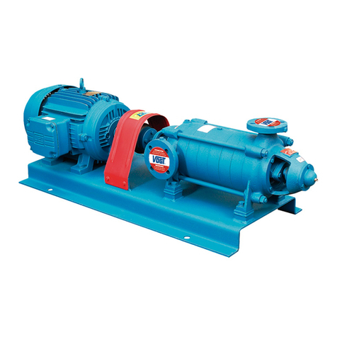
This manual deals with the installation, operation and maintenance of VOGT Monobloc
AM series centrifugal pumps.
The operation of a centrifugal pump, chosen in accordance with all the technical
background, can deliver for various causes, a poor service. This is generally due to
poor installation and/or operation of the pumping equipment.
Efficient service is only achieved by installing and operating the pumping equipment
correctly, therefore, the instructions in this manual must be fully complied with.
Pumps should not be used for purposes other than the service conditions stipulated at
the time of purchase.
The nameplate installed on the pump describes the most important features of the equipment purchased.
The design, materials and workmanship incorporated in the construction of VOGT pumps allow for a long, trouble-free
service life. The life and satisfactory performance of the VOGT pumping equipment, in any case, depend on a correct
application, installation and, in addition, of a periodic inspection and careful maintenance.
VOGT S.A. will not be responsible for physical injury, damage or other inconveniences caused by improper installation,
operation or maintenance.
The warranty is only valid when the equipment is used for the application for which it was ordered.
In case of any doubt or additional information regarding the installation, operation or maintenance of the pumping
equipment, contact qualified technical personnel by calling the head office or any authorized distributor.
VOGT S.A. reserves the right to make changes in design, dimensions, etc., at any time without notice and without
incurring any obligation.
The contents of this publication are based on the latest product information at the time of going to press.
No part of this publication may be reproduced without written permission from VOGT S.A.
This manual should be considered a permanent part of the pump and should remain with the pump if it is sold or moved.

3
Safety
Instructions
Indicates a procedure, operation, etc., with a strong possibility of severe personal injury, loss of life or irreparable
damage to equipment, if not performed properly.
Indicates a procedure, operation, etc., with a strong possibility of severe damage to the pumping equipment, if not
performed properly.
THE CONTENTS OF THIS MANUAL MUST BE READ AND UNDERSTOOD BEFORE INSTALLING AND OPERATING THE
PUMPING EQUIPMENT.
CAREFULLY READ AND UNDERSTAND THE MOTOR MANUAL, ATTACHED TO THIS MATERIAL, PROVIDED BY THE
MOTOR MANUFACTURER, BEFORE OPERATING THE PUMPING EQUIPMENT.
•Learn how to stop the pumping equipment quickly and understand the operation of all controls. Do not allow pumping
equipment to be used without proper instructions.
•Never place your hands, feet or any part of your body near rotating or moving parts.
•Never operate the pumping equipment if it is missing any protection from rotating parts.
•Always keep the pump at least one meter away from building walls or other equipment during operation to prevent fire
and to provide adequate ventilation.
•Always perform inspection before starting the pump. In this way you can avoid an accident or damage to the equipment.
•Children and pets should not go near the pump operation area, let alone touch the pump, as they could be injured by
touching the motor-driven equipment.
•Never place flammable items such as fuel, matches, etc., near the pump while it is running.
•Never place objects or items of any kind on the motor or pump, as this may create a fire hazard.
•Always maintain good cooling air circulation if the pump is to be operated in a small room.
!CAUTION
NOTE
!WARNING
!WARNING
2.1 Definitions
Provides useful information regarding a procedure, operation, etc., that facilitates the correct use of the pumping
equipment.
2.2 General Safety Considerations
Safety Instructions

4
Safety
Instructions
Safety Instructions
2.3 Qualification and Training of Operating Personnel
Personnel responsible for operation, maintenance, inspection and assembly must be suitably qualified and authorized.
The scope of responsibility and supervision of the personnel must be exactly defined by the plant operator. The plant
operator must ensure that the operating instructions are fully understood by the personnel.
2.4 Risks due to non-compliance with Safety Instructions
VOGT S.A. declines all responsibility that may arise from not respecting the safety standards in force at any time, during
the handling, installation or operation of its equipment.
The working conditions indicated in the order cannot be modified. Should this occur, VOGT S.A. must be informed.
Improper use outside the working conditions, or assembly/disassembly by untrained personnel may lead to risks to life,
the pump and other accessories in use or the normal operation of the equipment.
In order to benefit during the warranty period from the Guarantee offered by VOGT S.A., it is necessary that:
•The instructions in this manual have been correctly followed.
•The equipment is disassembled only by authorized personnel of our Technical Assistance Services or
directly by our factory personnel.
Any modification of the equipment must be previously consulted with VOGT S.A. For safety reasons, spare parts and
accessories authorized by VOGT S.A. must be used. The use of non-original spare parts exempts VOGT S.A. from any
responsibility.

Equipment
Description
Equipment Description
- 10 -
Figure 1
3.1 Pumping Equipment,
Main Components
1.- Discharge Flange
2.- Water Cutting Rubber
3.- Monoblock Shaft Clamp
4.- Motor Lifting Eyebolt
5.- Electric Motor
6.- Motor Terminal Box
7.- Pumping Equipment Base
8.- Union Body
9.- Pump Body
10.- Suction Mouth
11.- Priming plug
12.- Drain plug
The operation of a centrifugal pump, chosen in accordance with all the technical background, can give poor service for
various reasons. This is generally due to improper installation or mishandling of the pumping equipment.
Efficient service can only be achieved by installing the pump correctly, therefore, the instructions in this manual must be
complied with in their entirety. Pumps should not be used for purposes other than the service conditions stipulated at
the time of purchase. The nameplate installed on the pump describes the most important features of the equipment
purchased:
5
3.2 Identification Plate
1.- Height (mca)
2.- Electric Motor
3.- Pump Series
4.- Pump Model
5.- Pump Material Wetted Zone Pump
6.- Pump Type of Execution
7.- Sealing Type
8.- Nominal Impeller Ø
9.- Motor Cover Standard
10.- Impeller Ø
11.- Flow Rate (m³/h)
12.- Pump Serial No.
Figure 2

6
Equipment
Description
Figure 3
Equipment Description
3.3 AM Series Centrifugal Pump
3.3.1 AM Series Sectional Cutting, Models 701 and 751
3.3.2 AM Series Pump Parts and Parts Description, Models 701 and 751
Impeller
Pump Body
Union Body
Monoresorte Mechanical Seal
Angular Flank Suction
O'Ring Pump Body / Union Body
Check valve
Clamp Shaft
Pump Body Bolt / Union Body
Union Body Bolt / Motor
Suction Angle Flange Bolt
Clamp bolt
Priming plug
Drain plug
Golilla Water Cutter
Electric Motor
C-Din Flange Cover
1.07
2
3
11
13.01
19.01
22.01
23
25.01
25.13
25.18
25.22
30.01
30.02
38
100.01
101.01
NUM. DENOMINATION
Table 1

7
Equipment
Description
Figure 4
Equipment Description
3.3.3 AM Series Sectional Cutting, Models 744 and 733
3.3.4 AM Series Pump Parts and Parts Description, Models 744 and 733
Impeller
Pump Body
Union Body
Monoresorte Mechanical Seal
Angular Flank Suction
Straight Flank Unloading
O'Ring Pump Body / Union Body
Straight Flank Packing Discharge
Check Valve
Clamp Shaft
Pump Body Bolt / Union Body
Union Body Bolt / Motor
Straight Flank Bolt Discharge
Suction Angle Flange Bolt
Clamp bolt
Priming plug
Drain plug
Golilla Water Cutter
Electric Motor
C-Din Flange Cover
1.07
2
3
11
13.01
13.04
19.01
20.06
22.01
23
25.01
25.13
25.16
25.18
25.22
30.01
30.02
38
100.01
101.01
NUM. DENOMINATION
Table 2

8
Equipment
Description
Figure 5
Equipment Description
3.3.5 AM Series Sectional Cutting, Models 901
3.3.6 AM Series Pump Parts and Parts Description, Models 901
Impeller with Stem
Pump Body
Union Body
Register Cover
Monoresorte Mechanical Seal
Angular Flank Suction
O'Ring Pump Body / Union Body
O'Ring Register Cap
Check Valve
Clamp Shaft
Pump Body Bolt / Union Body
Union Body Bolt / Motor
Suction Angle Flange Bolt
Clamp bolt
Stud Stud Cap Register
Stud Nut Register Cap
Flat Stud Register Cap
Priming plug
Drain plug
Golilla Water Cutter
Electric Motor
C-Din Flange Cover
1.07
2
3
5.07
11
13.01
19.01
19.12
22.01
23
25.01
25.13
25.18
25.22
26.06
28.07
29.06
30.01
30.02
38
100.01
101.01
NUM. DENOMINATION
Table 3

9
Transportation,
Storage and
Handling
!WARNING
4.2 Factory Packaging and Protections
After the painting phase, VOGT S.A. performs the following:
•All openings are sealed by means of plastic parts, or plasticized adhesives.
•AM Series pumps are delivered in packaging consisting of a fully enclosed cardboard box mounted on a wooden
pallet. In all cases, the equipment is firmly secured to prevent movement during transport and handling. These
protections are exclusively for transport and at most for short term storage. In any case, the following storage
instructions must be followed.
CAUTION
4.3.1 Before Storage !
•Storage should be in a place protected from the outside, away from shocks, solar radiation, dust, humidity and
flooding.
•The pumping equipment should not be stacked on top of each other, even if the type of packaging makes this
possible.
•The pump and auxiliary lines should be kept clear of the pumping fluid.
•It is recommended to coat the unpainted parts of the pump with a protective material (e.g. petroleum jelly or
similar).
•Apply from the suction inlet oil or some anti-rust liquid in the wear ring areas, to avoid seizure.
•The electric motor shall be disconnected and the connection cables shall be removed and the terminal box shall be
closed with its cover.
•The electric boards shall remain in vertical position and disconnected.
Figure 6
Transportation, Storage and Handling
The pump and its components are heavy. Improper handling during handling and hoisting could cause serious personal injury
and/or damage to the equipment.
4.1 Transportation and Handling
The transport and handling of the equipment must be carried out with means suitable for the weight to be supported; the weight
is generally indicated on the delivery note, if this is not the case and there is no certainty of being able to handle the equipment,
please contact VOGT S.A. to indicate the same. For the handling, the equipments that require it have appropriate eyebolts on the
bench. However, remember that the equipment must never be lifted by means of the eyebolts of each one of its elements, e.g.,
engine and pump eyebolts, which are exclusive for their independent transport. Neither should the suction and discharge ports
of the pump, nor pipes or connecting elements, e.g. couplings, be used. In any case, if the equipment is to be lifted by means of
slings, these must pass under the pump and motor bodies.
4.3 Storage Instructions
These instructions are for storage less than 12 months from the date of shipment. If longer, please request instructions for long
term storage.

10
Transportation,
Storage and
Handling
•Remove the temporary protections and visually check the condition of all the elements.
•If the pump has been stored and/or stopped for a long period of time (more than 6 months), it is necessary to renew
the lubrication of the motor bearings as indicated in the motor manual.
•After a short storage period, it is sufficient to manually rotate the pump shaft to unlock the rotor assembly.
•Review and apply the short-term storage instructions specified in the manuals for the motor and other items used.
•Observe the other steps listed in the "Start-up" section.
If the equipment is going to be stopped for a certain period of time and there is danger of frost, it is necessary to drain the
pump completely to avoid its deterioration due to the possible freezing of the contained fluid.
Transportation, Storage and Handling
4.3.2 After Storage

11
Installation
Installation
!WARNING
•Pumps should always be installed in dry and clean locations. If the place of installation is humid, wet or with particles in
suspension, the appropriate motor should be selected for these conditions.
•When installing the pumping equipment, it should be protected from solar radiation, since this has a direct and negative
impact on the operation and useful life of the equipment, since it significantly increases the temperature and accelerates
the aging of paints and external surface finishes. Therefore, for equipment that is not installed in pump rooms or
similar, the installation of awnings or protective roofs should be considered.
•Sufficient space should always be left for disassembly and maintenance of the pump unit. In normal installations,
pumps should be located near the source of supply of the fluid to be pumped.
•Install the equipment well leveled and if possible on a solid concrete base with anchor bolts, to avoid vibrations and
displacements.
•The design of piping systems, anchorages and other areas of the installation is not the responsibility of VOGT S.A.
•VOGT S.A. only offers the data and comments as an aid, but cannot assume responsibility for the design, assembly and
operation of an installation. It is recommended that the client consult a specialist in the design of foundations, piping,
wells, etc. to complement and interpret the information provided by VOGT S.A. and to ensure correct operation.
5.3 Mounting Positions
AM Series pumps should be mounted horizontally, never mounted vertically or at an angle.
THE PUMP AND ITS COMPONENTS ARE HEAVY. IMPROPER HANDLING DURING HANDLING AND HOISTING COULD CAUSE
SERIOUS PERSONAL INJURY, LOSS OF LIFE AND/OR DAMAGE TO EQUIPMENT.
5.1 Checking the Pump on Arrival
Check upon arrival that the pump and accessories have not been damaged or lost in transit. If so, immediately report the
damaged or missing parts to VOGT S.A., to the authorized distributor or to the company that carried out the transport.
VOGT S.A. provides its Monoblock series pumping equipment, whose bases are designed to be placed on the foundation and
anchored with bolts, as indicated later in this manual. The possibility of grouting the carbon steel bases to the foundation is
at the customer's discretion.
5.2 General Rules for Locating Pumps

12
Installation
5.4 Foundations
Most pumps give the most satisfactory service when a rigid foundation is used. Foundations are usually made of
concrete, but can also be made of structural steel, in both cases they must be sturdy and non-vibrating.
If the foundation surface is concrete, it must be set horizontal and flat before the pumping equipment is placed. The
space required for a pumping unit and the placement of anchor bolts are defined by the drawings supplied by the
manufacturer.
The unit can be supported on a generously dimensioned foundation. This foundation must be completely flat, smooth
and level. The unit shall be fastened to this foundation by means of suitable anchor bolts to avoid possible vibrations
due to operation.
5.5 Anchor Bolts
VOGT S.A. supplies the pumping equipment with bases, these must be anchored to the foundation by means of anchor
bolts, as shown in figure 7 and applying the tightening torque according to table N° 4.
Figure 7
Base Carbon Steel
130
200
300
400
5 / 8
3 / 4
7 / 8
1
Nominal Bolt Ø
(Inch)
Tightening
Torque (Am)
Table 4 Anchor Bolt Tightening Torque
ANCHORING
CARBON STEEL
BASES
FOUNDATION
ANCHOR BOLT
SAFETY LOCKNUT
FIXING
NUT
CONCRETE
FOUNDATION
AA Cutting
BASE EQUIPMENT
SERIES AM
Once the process has been completed, it is advisable to mount a locknut on the bolt nuts to prevent them from loosening
during operation of the equipment.
5.6 Joints to Rigid Pipe System
For optimum operation of the motor-pump equipment, the piping should not exert stresses on it. The equipment can be
deformed, broken or misaligned when the piping is not aligned with the suction and discharge axes of the pump. The
position of the suction and discharge ports must be completely parallel, with their concentric axes, in order to minimize
stresses on the pump necks that could deform the pump or cause misalignment of the axes.
Do not use the pump as an installation fastening point. The suction and delivery piping must not produce stresses on the
suction and discharge ports of the pump that may exceed their maximum values. The pipes must be fixed to the walls or
floors of the pump room in such a way that the pump is not subjected to their weight, see figure 8.
Installation
!CAUTION

13
Installation
The diameters of the pipes, valves and fittings must be calculated according to the expected head losses in the installation
and in such a way that the fluid velocities are:
•Velocity in delivery pipe: 2 to 3 m/s.
•Velocity in suction pipe: 1 to 2 m/s.
To avoid pump cavitation, the available NPSH of the suction piping system must be higher than the NPSH required by the
pump. This is achieved by lowering the head loss of the suction piping, increasing its diameter, minimum possible length,
minimum number of fittings, not exceeding the required flow rate, low temperature (minus 33ºC if water, minimum negative
head and even better if the suction is positive.
If a long suction line is required, it should be installed with a continuous elevation slope in the direction of the pump and
without high points, to avoid the accumulation of air pockets, see figure 9.
Figure 8
Figure 9
If a reduction is installed in the suction line, it must be eccentric and its straight part must be at the top, to facilitate
the exit of trapped air bubbles to the pump, see figure 9.
Figure 10
10 x 0
0
The elbows and fittings installed on the pump suction must be selected and installed in such a way that the liquid
enters the impeller in a symmetrical and orderly manner, this is achieved by installing a section of pipe of the same
diameter as the pump suction and a length of 10 times that diameter, figure 10.
Installation

14
Installation
If the pump sucks under load, the suction pipe must be stagnant and with a diameter generally larger than the pump mouth. The
diffuser cone can be eccentric or concentric. Install a gate valve for isolation during maintenance, see figure 12.
Figure 12
Figure 11
VÁLVULA DE
RETENCIÓN
CHECK VALVE
10 x 0
Lc=7x(01-03)
0
01
03
Lc=7x(01-02)
10 x 0
0
01
02
4 x 0
0
Installation
The end of the suction pipe, which goes at the source of the fluid, should be submerged at least 4 times its diameter to avoid
the formation of vortices, which cause air to pass into the pump and cut off the liquid flow, figure 10.
After the suction and discharge pipes have been installed, they should be cleaned of any debris before starting up the
equipment, in order to avoid damage to the pump and other equipment installed in the system.
It is advisable to use a suction strainer in the suction pipe, amply dimensioned to prevent the entry of dirt larger than the size
allowed by the pump. Avoid sharp bends and fittings that narrow or widen abruptly (cones, valves, etc.).
The discharge piping should generally be larger in diameter than the pump discharge port. A gate valve should also be fitted to
regulate the flow and prevent possible overloading of the motor, as well as to isolate the pump during maintenance. To prevent
fluid backflow from the rising main, it is recommended that a check valve be placed in the rising main between the pump and
the control valve.
If the pump is in negative suction, the suction pipe must be absolutely stagnant and always rising towards the pump, with
diameter generally larger than the suction port of the pump. The diffuser cone for the adaptation shall be eccentric with the
upper part horizontal. Check that, at the normal working point, the NPSH required by the pump is at least 0.5 m lower than the
available NPSH of the installation. To prevent the pump from overpriming at a standstill, a foot valve should be placed at the
end of the suction pipe. It is recommended that the length of the cone diffusers be at least 7 times the difference of the nominal
diameters of the inlet and outlet of the cone, see figure 12.

15
Installation
Figure 13
EXPANSION JOINT
EXPANSION JOINT
CHECK VALVE
Installation
5.7 Expansion Joint
Dimensional changes in piping and equipment, caused by variations in the working temperature of the piping system and the
pump, either by the temperature of the pumped fluid or by exposure to changing environmental conditions, result in large
magnitude stresses and forces that are transmitted to the pumping equipment and can damage it. That is why VOGT S.A.,
recommends the use of expansion joints as part of the piping system that connects to the pump, when conditions warrant it, see
figure 13.
Even though the absorption of axial movements, caused by temperature changes, is the main work performed by the expansion
joints, they also act as vibration isolators reducing the propagation of vibrations, produced by the operation of the equipment,
through the piping system and also act as compensators of lateral, angular and torsional movements.
Start-up
Start-up
A self-priming pump must be primed at the first start-up or in very spaced runs. Priming consists of filling only the pump
body with the liquid to be pumped. When the pump starts operating, the design of the pump causes the liquid contained in it
to start producing a vacuum that extracts the air from the suction pipe and the liquid starts to rise, after a few minutes it
reaches the pump and normal pumping starts.
When the pump stops the liquid can be suspended by the check valve and the pump is primed, this allows it to pump
immediately when it starts up again.

16
Start-up
•Disconnect the motor from the mains.
•Remove the priming plug on the top of the pump body.
•Pour liquid through the delivery pipe until it overflows through the priming hole.
•While priming, rotate the pump shaft by hand to break any sticking.
•Replace the priming plug in its position.
Never run a pump dry. Most centrifugal pumps have a mechanical seal or stuffing box, therefore they cannot be run dry
under any working conditions, otherwise the sealing elements will be seriously damaged.
Before starting the pump, the suction pipe must be completely filled with the fluid to be pumped, this allows the pump to
start always primed and prevents the accumulation of air in the suction system. The procedure is as follows:
6.2 Pump Priming
6.3 Minimum Flow Rate
It must be taken into account that there is a minimum flow rate at which the pump must work, which is given by the
temperature of the pumped fluid, according to the following table.
0ºC < T < 50 ºC => 20% of the flow rate of the maximum efficiency point
50ºC < T < 80 ºC => 30% of the flow rate of the maximum efficiency point
6.4 Pumped Fluid Density
The power required for pump operation increases directly with the density of the pumped fluid. In order not to overload the
electric motor, it must be ensured that the pumped fluid corresponds to that which was originally considered for the
selection of the pump and its motor.
6.5 Checks on Electric Motor
When making the electrical connection, make sure that the type of current and rated voltage indicated on the motor
nameplate are in accordance with the type of current and voltage of the power supply at the place of installation.
Check the direction of rotation of the motor by running it for a moment. The direction of rotation must correspond to that
indicated by the arrow engraved on the pump body. If the direction of rotation is not correct, two phases must be inverted in
the terminal box of the motor (if it is a three-phase motor). Follow the indications described in the motor manual. The electric
board must be suitable for the type of motor drive, direct start, star-diagonal, soft starter, etc.
Verify that the degree of insulation and protection of the motor corresponds to the conditions in which it will operate.
!CAUTION
NOTE
Start-up
6.1 Before Start-up
After a pump has been installed and all mechanical, hydraulic and electrical connections have been made, it is ready for
commissioning. However, prior to initial start-up, the following is recommended:

17
Start-up
It is important to check before the first start-up that the technical specifications of the motor, which come on the nameplate,
correspond to the technical characteristics required by the pump and those of the place where the motor is going to operate.
Verify that:
•The characteristics of the mains supply, voltage, number of phases, frequency, and amperage match those of the
motor.
•The electrical panel must be suitable for the type of motor drive, direct start or star-delta.
•The degree of insulation and protection of the motor must correspond to the conditions in which it will operate.
•Before final start-up, it is necessary to check the direction of rotation to prevent damage to the thrust assembly. The
direction of rotation of the motor is correct when it coincides with the direction indicated by the arrow cast on the
pump body (counterclockwise when looking at the motor facing the shaft).
6.6 Engine Considerations !CAUTION
6.7 Other General Operating Considerations
DO NOT throttle the suction of the pump, when the suction of a centrifugal pump is throttled, a reduction of the absolute
pressure at the impeller inlet is originated. This is very harmful for the pump, since it causes erosion and premature
destruction of its components, product of the phenomenon called cavitation. Suction throttling is only allowed when the
available NPSH of the installation exceeds by a wide margin the NPSH required by the pump.
If the pump is stalled or rotates with difficulty, the equipment must not be operated until the cause of the problem is located
and solved.
6.8 Rotation Management Control
Before final start-up, it is necessary to check the direction of rotation to ensure correct operation of the pump.
Correct direction of rotation
The motor cables are marked with the letters U-V-W, and should be connected to the corresponding U-V-W terminals on the
control panel. Identify and mark the power supply terminals R-S-T, using a cyclic phase detector with a clockwise rotating
indicator, and connect them to the R-S-T terminals on the control panel.
If you do not have a cyclic phase detector, precede as indicated. Connect the power supply cables to the control panel and to
the power supply circuit, just for a moment, and observe in which direction the motor-pump assembly tends to rotate. The
direction of rotation of the motor is correct when the assembly tends to rotate in the direction indicated by the arrow cast on
the pump. If the motor pump tends to rotate in the opposite direction to that indicated by the arrow, reverse the position of
any two power cables and you will obtain the correct direction of rotation.
Start-up

18
Start-up
To make a delta connection, the bridges are placed in the electric motor box connecting: U with Z, V with X, W with Y. The
wires from the electric panel to the motor junction box connect the terminals: U to U, V to V, W to W, (see fig. No. 14-a).
To make the star connection connect together the three terminals: X-Y-Z of the junction box and connect the terminals U-V-
W with the corresponding terminals U-V-W on the electric panel. The power supply terminals R - S - T must be connected
to the power supply busbars or terminals on the electric panel (fig. No. 14-b).
Figure 14 a Figure 14 b Figure 14 c
Motors with 6 wires can be started using a Star/Delta splitter only if the supply line voltage is equal to the minimum voltage
shown on the nameplate, between the two values specified by the manufacturer. To make the star-delta connection, in the
motor box, all jumpers are removed, leaving the terminals free. The 6 wires from the board to the motor connect the 6
terminals of the board to the 6 terminals of the motor junction box as follows: U to U, V to V, W to W, Z to Z, X to X, Y to Y.
(see fig. No. 14-c).
Designation of the Power Cables of
the Three-Phase Lines By Different
Manufacturers
R = L1
S = L2
T = L3
Designation of Cables and Terminals of
Three-Phase Electric Motor Coils by
Different Manufacturers
X
Y
Z
4
5
6
U2
V2
W2
=
=
=
=
=
=
U1
V1
W1
=
=
=
U
V
W
1
2
3
=
=
=
Start-up
6.8.1 Instructions for the Connection of Three Phase Electric Motors
Electrical
Panel
Electrical
Panel
Electrical
Panel

19
Maintenance
•Adequate and periodic maintenance of the equipment is essential to obtain a good level of performance and an extension of
the service life.
•For the motor, the required service intervals and the type of maintenance to be performed are described in the MAINTENANCE
SCHEDULE described in the respective motor manual provided by the manufacturer.
•It is recommended that the pump be overhauled at the factory EVERY 3000 OPERATING HOURS OR ONE YEAR, whichever
comes first.
•If the pump has been used with water containing suspended solids, sludge, etc., it should be cleaned with clean water after
the work is completed, in order to reduce corrosion, erosion and remove sediments.
•ALWAYS USE ORIGINAL SPARE PARTS for maintenance or repair. The use of replacement parts that do not have the same
quality can damage and shorten the useful life of the equipment.
7.2 Engine Lubrication
Motor lubrication should be carried out according to the indications given by the motor manufacturer. However, consider that
some motor manufacturers for their standard lines, contemplate that motors of less than 50 HP do not need relubrication since
these motors have sealed bearings, therefore only motors of more than 50 HP need relubrication.
7.3 Electric Motor Drive
Each electric motor has a degree of protection that must satisfy each particular situation; in order to carry out a program of
revision and cleaning of its internal components, it is advisable to carry out voltage and amperage controls on each phase
separately.
7.4 Mechanical Seal
The mechanical seals used as standard in the Monobloc series pumps are of the unbalanced internal monospring type. This
spring produces the minimum contact force between the sealing surfaces of the rotating and stationary units. The stationary
unit is mounted on the junction body in an elastomer cup. Its design allows the sealing surfaces to remain in contact, even if
natural wear or axial and radial oscillations occur in the rotation of the unit. These seals consist of the following elements:
Maintenance
7.1 General Considerations !CAUTION
Ceramics
Coal
Buna
Buna
AISI 302
AISI 302
A
B
C
D
E
F
Mono-Spring, Unbalanced
Basic
TableNº 5
Figure 15
Stationary Ring
Contact Face
Elastomeric Semi Bellows
Cup Type Seat
Spring
Chassis
Ceramics
Coal
Vitón
Vitón
AISI 302
AISI 302
Mechanical Seal
PAC-SEAL Type 21 Seal
Alternative

20
Maintenance
Maintenance
Newly installed mechanical seals may leak liquid between their sealing faces, this is small and should diminish with some time
of operation. Mechanical seals do not require maintenance, but when they have completed their service life, they should be
replaced completely with new seals.
When a seal is to be installed, always remember that it should be done with the utmost care and cleanliness, so the contact
protection between the two sliding surfaces should be removed only at the time of assembly.
Table of contents
Other Vogt Water Pump manuals
Popular Water Pump manuals by other brands

Sandpiper
Sandpiper s05 Service & operating manual

SymCom
SymCom PumpSaver Plus 235P installation instructions

Makita
Makita EW1050H instruction manual

salmson
salmson IMMERSON S Installation and starting instructions

salmson
salmson SXE-DXE Installation and starting instructions

Simer
Simer SMART GEYSER 2330-03 owner's manual

Parker
Parker Commercial Hydraulics PGP030/031 Series Service manual

Graco
Graco saniforce 2150 Operation

Graco
Graco Merkur W10CAS Assembly

3P PRINZ
3P PRINZ Pompe 3P M Series Instruction & maintenance manual

Balcrank
Balcrank Lynx Series Operation, installation, maintenance and repair guide

Balcrank
Balcrank Lynx Operation, installation, maintenance and repair guide