Vogt HAD Series User manual


2
Introduction
Introduction
VOGT is a company that provides comprehensive solutions in fluid handling
equipment according to the needs of the mining industry. Accordingly, VOGT offers a
range of pumping equipment capable of operating at high demands in slurry fluids that
reduce the cost of operation, maintenance and initial investment. VOGT Pumps offer a
high resistance to wear, thus increasing the useful life of its components.
The main purpose of this manual is to provide the necessary information for
installation, maintenance and start-up of the VOGT HAD Series pumps. In order to
increase the productivity of the equipment, it is recommended to carefully follow the
instructions below.
Store equipment indoors and cover flanges from contact with the environment.
Apply rust preventative coating to ground areas and rotate shaft on average once a month. Kendall Seal N Sound or
similar product is recommended.
For storage longer than 18 months, consider proper drainage of the pump and purge the labyrinth with grease to avoid
contamination of the bearings. Re-pack for long periods of time.
2.1 Indispensable to Maintain VOGT Warranty

3
Safety
Instructions
• The contents of this manual must be read and understood before installing and operating the pumping equipment.
• Carefully read and understand the motor manual, provided by the motor manufacturer, before operating the pumping
equipment.
• Learn how to stop the pumping equipment quickly and understand the operation of all controls. Do not allow the pumping
equipment to be used without the necessary instructions.
• Never place your hands, feet or any part of your body near rotating or moving parts.
• Never operate the pump without safety devices installed.
• Never operate the pumping equipment if any protection of the rotating parts is missing.
• The direction of rotation of the motor has to be checked before connecting belts or couplings. Operating the pump in the
wrong direction can cause accidents to personnel and damage to the equipment.
• Always carry out the inspection before starting the pump in order to avoid an accident or damage to the equipment.
• Never place flammable items such as fuel, matches, etc., near the pump while it is running.
• Never place objects or items of any kind on the motor or pump as this may create a fire hazard.
• The pump should not be operated at low or near zero flow conditions as this may cause vaporization of the pumped liquid,
the high pressure generated may cause accidents to personnel and damage to equipment. Slurry pumps should not be
operated at a flow rate less than 25% of BEP (Best Efficiency Point) for a given RPM level, as equipment damage and injury
could result.
• Never apply heat to remove the impeller, disassemble the pump or any part of it, as this could result in an explosion of the
trapped liquid.
• Never operate the pump beyond the operating range for which it was ordered.
• Always disconnect electrical power to the motor before performing repair and maintenance work.
• Never lift the complete equipment (pump-motor-bank assembly) by any part other than the lifting shackles with which the
structural frame is equipped.
!WARNING
VOGT S.A. INFORMS THAT CONTINUOUS OPERATION OF CENTRIFUGAL PUMPS WHEN SUCTION AND DISCHARGE ARE
BLOCKED IS POTENTIALLY DANGEROUS. EXCESS HEAT IS GENERATED WHICH VAPORIZES THE TRAPPED LIQUID.
THIS CAN CAUSE AN EXPLOSION WHICH CAN BE LIFE-THREATENING.
2.2 General Warnings
Safety Instructions

4
Safety
Instructions
Safety Instructions
•Never lift pumping equipment components and subassemblies (motor, pump, etc.) by anything other than the
proper lifting eyebolts suitable for each individual operation.
•Do not work under suspended loads.
•Never change the operating conditions without the respective approval and authorization of VOGT S.A.
•Check belt tension before starting up the equipment.
•Prime pump before operating, to avoid solid particles settling on start-up and causing equipment jamming.
•Do not pump very hot liquid into a cold pump or very cold liquid into a hot pump. The sudden change in
temperature will damage internal components and cause the pump casing to rupture.
•Use care when handling worn components with sharp edges (wear gloves during each maintenance operation).

Pump
Identification
- 10 -
5
Pump Identification
3.1 Pump Identification Codes
Each VOGT Pump has a nameplate on the base where the Pump model is identified. Each digit or letter of the equipment
code refers to the following:
Example:
40/25 2-HAD:
Inlet diameter of 40 [mm].
Discharge diameter of 25 [mm].
2 = bearing holder size
HAD= VOGT HAD Series pump, with interchangeable liners
A. Suction diameter is expressed in millimeters, e.g. 40, 50, 75, 100, etc.
B. Discharge diameter is also expressed in millimeters, such as 25, 40, 50, 75, etc.
C. The pump bearing carrier consists of a casing and bearing assembly. The size of the casing is identified between
one and four numbers, such as 2, 4, 5, 2021, etc.

6
Transaction
Information
Transaction Information
The pump performs its pumping work by means of the centrifugal rotary action of the impeller rotating inside the casing
and for everything to work properly the following considerations must be kept in mind:
1. Complete check of the entire pumping system prior to start-up. Piping properly aligned to the pump, valves in good
condition, controls operational, pump alignment and belt tension checked, etc.
2. GAP between impeller and suction disk should be checked. This should be between 1 and 2 [mm], to increase
efficiency and decrease recirculation inside the equipment.
3. Activate the water seal system before starting the pulp pump, adjust flow and pressure according to the equipment
requirements. This operation is performed with the pump in commissioning to verify water flow through the jacket.
4.1 Pump Baseplate
Before leaving the factory, the pump and its motor unit are mounted on a level base that serves as an assembly stand.
For alignment in the field, compensating bases (slats) are used to lift the motor if necessary for the correct assembly of
the motor-pump assembly. The bases installed on the foundation in the equipment installation area will support the base
of the assembly. Once the base of the assembly is installed and tightened against the foundation, the alignment of the
equipment is started, using the lag bolts if necessary.
4.2 Foundations
The foundation supporting the pump-motor assembly must be able to withstand vibrations of both the pump and the
motor and should be as close as possible to the source of the fluid to be conveyed. The motor pump assembly should
be supported on a generously sized foundation. This foundation must be completely flat, smooth and level. The unit shall
be tied to this foundation by means of suitable anchor bolts to avoid possible vibrations due to operation. The space
required for a pumping unit and the placement of anchor bolts are defined by the drawings supplied by the
manufacturer.
4.3 Alignment of the Axis
Regardless of whether they are direct coupled or belt driven, the pump and motor shaft must be precisely aligned.
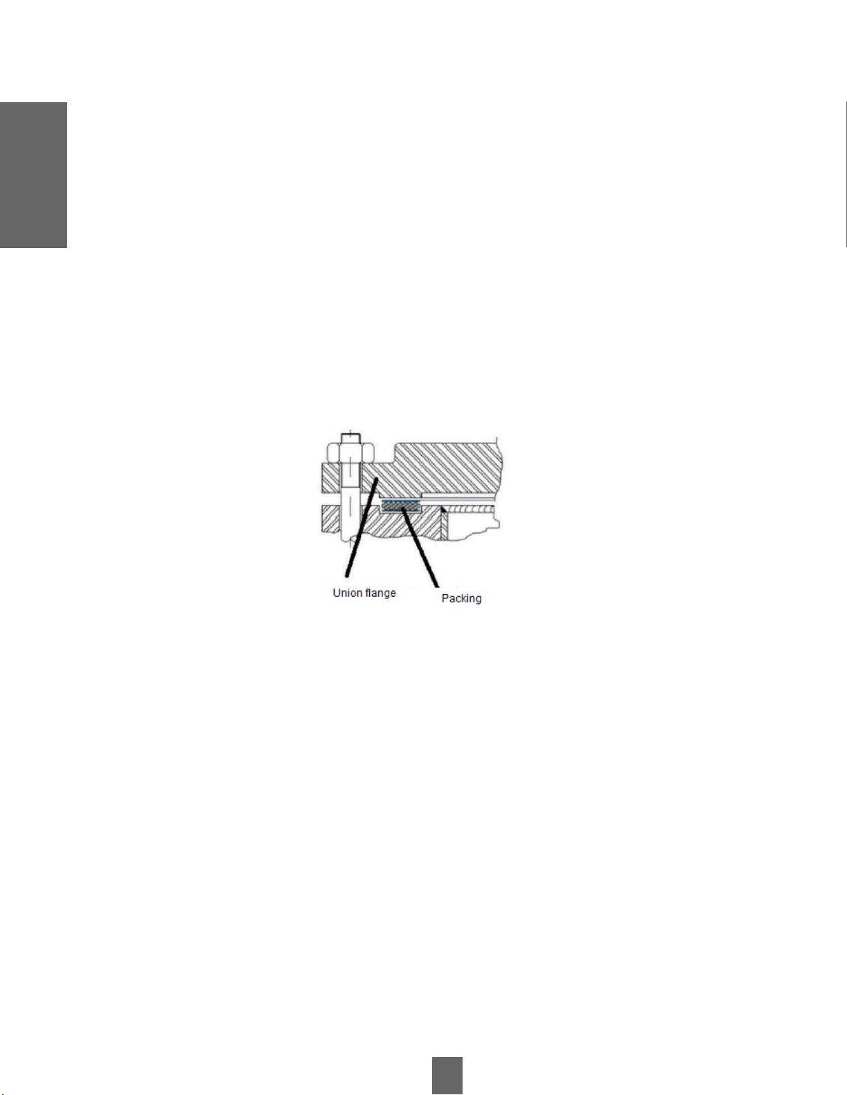
4.4 Pipelines
For optimum operation of the pump-motor unit, the piping should not exert stresses on it, since the unit can deform,
misalign or break when the piping is not correctly aligned with the suction and discharge shafts of the pump. The
position of the flanges must be totally parallel, with their concentric axes, in order to minimize stresses in the pump
necks that deform the pump or produce a misalignment of axes. The bolts or studs must be able to pass loosely through
the holes in the flanges. Do not use the pump as an installation fastening point. The suction and delivery piping must not
cause stresses on the pump flanges that could exceed their maximum values. The piping should be fixed to the walls or
floors of the pump room in such a way that the pump is not subjected to the weight of the piping.

7
Figure 1. Typical flange arrangement
Transaction Information
4.5 Suction Conditions
The suction and discharge system should be adequately insulated to ensure cleanliness and maintenance of the pump
when required. The suction piping should be as short as possible and have few bends. The pipe diameter should be
calculated for the minimum slurry velocity thereby reducing head losses, but keeping the velocity above the settling
velocity of the solid particles.
When the diameter of the suction pipe is larger than that of the pump flange, a reduction should be used whose shape
avoids the formation of air bubbles that then enter the pump.
Transaction
Information

8
Pump Start
- Water pressure should be approximately 10 to 15 [psi] higher than pump discharge pressure.
- Clean water, free of impurities.
- Maintain system flow rates within the parameters given in Table 1.
Pump Start
Before putting a VOGT pump into operation for the first time, the following steps should be taken:
5.1 Water System Control Seal
Water System Control Seal
5.2 Axis Unlocking
In case the shaft becomes blocked during transport, use the shaft wrench to rotate the shaft manually in the direction
indicated on the pump housing.
5.3 Motor Rotation Control
With the motor and pump uncoupled, check that the pump rotates freely in the direction indicated on the pump casing,
otherwise the impeller could unscrew causing serious accidents.
5.4 Pump Start
The bearing carrier is supplied with an initial grease charge from the factory, therefore no additional grease should be
added at start-up.
The following graph establishes a comparison between typical times and temperature characteristics of a new grease
lubricated bearing carrier.
Table 1: Range of flow rates per installed bearing carrier

9
Pump Start
Initial Start-up
Next Starts
Figure 2. Time compared to temperature characteristics of a grease lubricated bearing assembly
The most common causes of high initial temperatures are:
-Excessive grease in bearings during initial start-up due to excessive relubrication.
-Belt drive tension is high for initial operation.
-Operation while idle state is indicated.
-Initial grease load is high to improve the chance of the bearings surviving the initial storage period.
!WARNING
-Do not add grease during start-up and initial operation.
-Check belt tension.
-Run the pump at the active operating point.
-According to the graph in figure 2, the temperature should not exceed a pick of 105°C, then wait approximately 4 hours
to cool it down and test it again. The pick should go down until it stabilizes.
If the assembly continues to heat up, recheck belt tension, operating point and speed. Check:
- Presence of solid particles inside. It is recommended to split the tests with water.
- Verify system pressure and flow.
Pump Start

10
Pump Start
NOTE
The equipment should operate by controlling the flow, discharge pressure and motor speed mentioned within the
operating curve of the equipment, based on this the pump should not work in a range less than 25% at the highest
efficiency point (BEP).
Prime the pump when it is to be put into operation.
The water leaking from the stuffing box is warmer than the water flowing through the pump due to the friction between
the jacket and the packing installed inside the system. If the water leakage through the stuffing box is very low and
causes smoke or steam, the pump should be stopped and its installation checked.
Abnormal start-up
If the pump does not prime, it may be due to one or more of the following causes:
- Pulp accumulation in the suction pipe.
- Air entering the packing press.
- Impeller blockage by oversize or oversize solid material (clogging).
- Blockage in the discharge duct either by oversize particles, flow velocity less than the settling velocity or by the
discharge angle of the line.
5.5 Shutdown Procedure
Before turning off the pump, you should let it run for a short period only with clean water to free the system of
impurities, then turn off the control panel equipment to finally and after a while at lower power stop the water system
seal.
Pump Start

11
Pump
Maintenance
FRAME SIZE
BEARING HOLDER
ADD
[gr]
RPM OF THE BEARING HOLDER
200 300 400 600 800 1000 1200 1500 2000 2500 3000 4000
2 6 3000 2400 1800 1500 1000 800 650 300
3 9 3600 2400 1800 1600 1200 900 580 500 *
4 14 2500 2000 1500 1200 800 500 500
6 35 7000 4200 2000 1800 1200 700 400 400
19 50 3000 2000 1400 1000 600 400 400
2021 66 3800 2800 1500 900 500 300
2122 125 4800 3000 1800 900 400 400
19 33 3000 2000 1400 1000 600 400
2021 50 3800 2800 1500 900 500 300
2122 42 4800 3000 1800 900 400 400
Suggested lubrication interval (hours) based on Mobil XHP 222 standard mineral grease
Table 3: Recommended grease used
Pump Maintenance
6.1 Impeller Adjustment
As mentioned above, pump efficiency and component wear rate vary as a function of the GAP between the impeller and
the pump. Accordingly, the pump should have a GAP between 1 and 2 [mm] to achieve the best performance. For a
pump with centrifugal seal it is recommended to double this difference, so as not to increase the seal area pressure.
6.2 Bearing Lubrication
For reliable operation it is recommended to regularly inspect the bearing temperature and determine the frequency, the
amount of lubricant to be added and the date of the next inspection. These depend on the size of the bearing holder, the
operating speeds and mainly on the judgment of the field maintenance team according to the measured bearing
temperatures.
6.3 Grease Lubricants
Grease with the following technical specifications is recommended:

12
!WARNING
Pump Maintenance
Table 2 is referential, field judgment during operation is essential. Normal operating conditions include:
• Clean environment.
• Pumps covered or protected from the weather (rain, snow, ice, dust, etc.).
• Normal ambient temperatures (0 - 35°C).
• Properly installed stuffing box.
Figure 3. Lubrication points for bearing carrier
Table 4. Recommended amount of grease for initial use in each bearing
Pump
Maintenance

13
Table 5. Grease lubrication intervals / labyrinth seals
Pump
Maintenance
Pump Maintenance
6.4 Lubricants - Oil
The oil used in all oil lubricated bearing assemblies should be as specified in this item. Oils with viscosities higher than
recommended are likely to cause excessive churning and heat generation in the bearing assembly.
Oil lubricated bearing assemblies should operate partially submerged. Sealing at both ends is by lip seals and piston
rings.
Figure 4. Lubrication level
The labyrinth seals at both ends should be lubricated with grease providing additional security for extended lip
seal / bearing life.
Grease purge labyrinth
The labyrinth grease purge is used to prevent contaminants from entering the bearing assembly, thereby
prolonging bearing life and lowering maintenance costs. Therefore, careful attention paid to labyrinth grease
purging is an essential maintenance requirement.

14
Table 6. Service Intervals
Table 7. Oil Volume 100/75 #4-HAD Pump
Pump
Maintenance
Quantity of oil
Pump Maintenance
The grease that escapes outward along with the centrifugal effect when the pump is running keeps the labyrinth purged
of grit and moisture. To improve purging, particularly at the wet end of the bearing assembly, replace the standard
labyrinth grease purge nipple with an automatic grease feeder system (three-month capacity on smaller bearings and
one-month capacity on larger ones). In this case, check at regular intervals that it is not completely discharged.
6.5 Oil service intervals and quantities
This section contains information on service intervals and required amounts of oil lubrication for bearing assemblies.

15
•Shell Omala 150 or equivalent.
•Grease (to purge grease from the labyrinth).
Table 8. Grease Specifications Labyrinth Seals
- For general applications: Mobil HP or equivalent.
- When water splashing is likely: Shell Calinthia T or equivalent.
Pump
Maintenance
Pump Maintenance
6.6 Recommended Lubricants

16
Parts and
Assembly
NOTE
- The labyrinth type lock nut has left hand threads.
It is very important to clean the housing, covers, shaft and any component that may have impure materials when
installing new bearings.
Figure 5. Placement of lubricating grease retainers and bearing cones
Parts and Assembly
7.1 Wear Components
The service life of wear parts, such as impellers and liners, varies with the pump and installation. If the pump
performance drops, the replacement of wear components or adjustment of the impeller setting should be evaluated
depending on their condition.
It is recommended to measure wear parts from time to time at the beginning in order to develop a maintenance plan.
7.1.1 Bearing Assemblies (Up to Size 6)
This section contains information for pumps designed as indicated above and as shown in Figure 5. The pump bearing
housing configuration consists of opposed tapered roller bearings.

17
· Apply oil or light grease to the flat surfaces of the bearing and shaft.
· Slide a LUBRICATING GREASE RETAINER.
· The tapered bearing is installed with the larger diameter against the retainer installed in step 2. To preheat the
bearing it is recommended not to exceed 120°C.
· Install the other grease retainer.
· Spray the bearings with a dehydrating fluid to remove all moisture.
· Apply oil or light grease to the inside diameter of each end of the BEARING COVER.
· Press the bearing holder cap onto one end of the bearing holder until it is just below the face of the end of the cover.
Figure 6. Placing the impeller end bearing holder cover on the impeller housing
Figure 7. Positioning of the shaft in the bearing holder cover
Parts and Assembly
7.2 Lubricating Grease Retainers and Tapered Bearings Assembly (fig. 5)
7.3 Placement of the Impeller End Bearing Cap in the Housing
Parts and
Assembly

18
•The cap is placed with a gasket (symmetrical cap on both sides). Use thick only for sealing, usually 0.018" to 0.020".
•Tighten screws evenly.
Parts and Assembly
The cover of the bearing holder is symmetrical and the lid can be placed at either end. The small diameter of the cap should
face the front. For single row tapered bearings, the caps and cones are non-matching and can be interchanged. Assembly
will be easier if you hold the cover vertically.
7.4 Attaching the Shaft to the Bearing Housing (fig. 6)
For assemblies up to size 3, this procedure can be performed with the housing in the horizontal position. For larger sizes, it
is advisable to assemble in a vertical position so that the bearings will fit concentrically.
Place this grease by hand on the bearing housing shaft to fill the space between the bearings and the bearing housing (both
ends).
Take shaft from threaded end and when inserting into bearing housing tap with a mallet lightly and evenly.
Place the cover on the housing and screw the bolts on it.
The shaft should barely rotate and there should be practically no axial play.
7.5 Separation Measurement (Drive Side)
Measure the gap between the bearing housing cover and the housing for installation of the gaskets. Once installed, close the
assembly and tighten the cover bolts securely again.
7.6 Mounting Labyrinths, Piston Rings and Bearing Seals (fig. 8)
Grease each SEAL and fit it into the groove of the Labyrinths with the lip pointing towards the inside of the Bearing Housing.
Grease the two PISTON RINGS and fit them into the grooves of each Labyrinth. Leave the joints in diametrically opposite
position.
Slide the labyrinths onto the shaft. The labyrinth corresponds to the motor side. Push the labyrinths into the Cover until the
Piston Rings prevent further entry.
Insert two ALLEN BOLTS into the motor side Labyrinth and secure it against the Shaft.
Confirm that the Shaft turns freely.
Install the PLUGS in the Bearing Housing and the automatic grease nipples in both Covers.
Parts and
Assembly

19
Once the bearing carrier cover on the drive side has been moved as shown in Figure 8 and all bolts have been
tightened properly, it is necessary to measure the actual axial play in the bearing carrier.
Table 8. Axial set specifications
Figure 8: Assembly of labyrinths, piston rings and bearing seals
Figure 9. Measurement of axial clearance
Parts and Assembly
7.7 Axial clearance check
Parts and
Assembly

20
Parts and Assembly
Figure 10. Verification of axial clearance - Vertical
7.8 Smaller Sizes (2-3-4-5)
In horizontal position add a mounting bracket with a dial indicator secured to the cover as shown in figure 9. Rotate the
shaft and record the maximum and minimum.
7.9 Larger Sizes (6-18-19-2021-2122)
Position the bearing holder vertically as shown in figure 10 and repeat the process above leaving the pump side shaft
upwards.
Parts and
Assembly
This manual suits for next models
11
Table of contents
Other Vogt Water Pump manuals
Popular Water Pump manuals by other brands

Wayne
Wayne Shallow Well SWS50 Operating instructions and parts manual

Aussie Pumps
Aussie Pumps QP60TDK Series Operations & parts manual

Yamaha
Yamaha YP30G owner's manual

RODEX
RODEX RDX8501 instruction manual

PYD Electrobombas
PYD Electrobombas KBS Series Operating and maintenance manual

laguna
laguna Utility Pump 1 manual