Vogt VCBS Series User manual


2
Introduction
Introduction
The nameplate installed on the pump describes the most important features of the equipment purchased.
The design, materials and workmanship incorporated in the construction of VOGT pumps allow for a long, trouble-free
service life. The life and satisfactory performance of the VOGT pumping equipment, in any case, depend on a correct
application, installation and, in addition, of a periodic inspection and careful maintenance.
VOGT S.A. will not be responsible for physical injury, damage or other inconveniences caused by improper installation,
operation or maintenance.
The warranty is only valid when the equipment is used for the application for which it was ordered.
In case of any doubt or additional information regarding the installation, operation or maintenance of the pumping
equipment, contact qualified technical personnel by calling the head office or any authorized distributor.
VOGT S.A. reserves the right to make changes in design, dimensions, etc., at any time without notice and without
incurring any obligation.
The contents of this publication are based on the latest product information at the time of going to press.
No part of this publication may be reproduced without written permission from VOGT S.A.
This manual should be considered a permanent part of the pump and should remain with the pump if it is sold or moved.
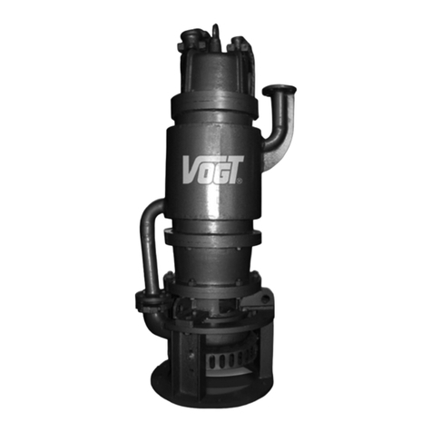
This manual deals with the installation, operation and maintenance of tripod mounted
vertical cantilever centrifugal pumps. This manual should be read and understood
before installing and operating the pumping equipment.
The operation of a centrifugal pump, chosen in accordance with all the technical
background, can give poor service for various reasons. This is usually due to poor
installation and/or operation of the pumping equipment.
Efficient service is only achieved by installing and operating the pumping equipment
correctly, therefore, the instructions in this manual must be fully complied with.
Pumps should not be used for purposes other than the service conditions stipulated at
the time of purchase.

3
Safety
Instructions
Indicates a procedure, operation, etc., with a strong possibility of severe personal injury, loss of life or irreparable
damage to equipment, if not performed properly.
Indicates a procedure, operation, etc., with a strong possibility of severe damage to the pumping equipment, if not
performed properly.
THE CONTENTS OF THIS MANUAL MUST BE READ AND UNDERSTOOD BEFORE INSTALLING AND OPERATING THE
PUMPING EQUIPMENT.
CAREFULLY READ AND UNDERSTAND THE MOTOR MANUAL, ATTACHED TO THIS MATERIAL, PROVIDED BY THE
MOTOR MANUFACTURER, BEFORE OPERATING THE PUMPING EQUIPMENT.
•Never apply heat to remove the impeller. An explosion of the trapped fluid could result.
•Never use heat to disassemble the pump or any part of it, as there is a risk of explosion of the fluid trapped in it.
•Never operate the pump without the core cover properly installed.
•Never operate the pump beyond the operating range for which it was ordered.
•Never change the service conditions without the respective approval and authorization of VOGT S.A.
•Always disconnect electrical power to the motor before performing repair and maintenance work.
•Never operate the pump without safety devices installed.
•Learn how to stop the pumping equipment quickly and understand the operation of all controls. Do not allow the pump to
be operated without the necessary instructions.
•Never place your hands, feet or any part of your body near rotating or moving parts.
•Never place flammable items such as gasoline, matches, etc., near the pump while it is operating as this may create a fire
hazard.
•Never place objects or items of any kind on the motor, as this may create a fire hazard.
•Never lift the pumping equipment by anything other than the lifting eyes.
!CAUTION
NOTE
!WARNING
!WARNING
2.1 Definitions
Provides useful information regarding a procedure, operation, etc., that facilitates the correct use of the pumping
equipment.
2.2 General Safety Considerations
Safety Instructions

4
Safety
Instructions
Safety Instructions
2.3 Qualification and Training of Operating Personnel
Personnel responsible for operation, maintenance, inspection and assembly must be suitably qualified and authorized.
The scope of responsibility and supervision of the personnel must be exactly defined by the plant operator. The plant
operator must ensure that the operating instructions are fully understood by the personnel.
2.4 Risks due to Non-Compliance with Safety Instructions
VOGT S.A. declines all responsibility that may arise from not respecting the safety standards in force at any time, during
the handling, installation or operation of its equipment.
The working conditions indicated in the order cannot be modified. Should this occur, VOGT S.A. must be informed.
Improper use outside the working conditions, or assembly/disassembly by untrained personnel may result in risks to
life, the pump and other accessories in use or normal operation of the equipment.
In order to benefit during the warranty period from the Guarantee offered by VOGT S.A., it is necessary to:
•The instructions in this manual have been correctly followed.
•The equipment is disassembled only by authorized personnel of our Technical Assistance Services or
directly by our factory personnel.
Any modification of the equipment must be previously consulted with VOGT S.A. For safety reasons, spare parts and
accessories authorized by VOGT S.A. must be used. The use of non-original spare parts exempts VOGT S.A. from any
responsibility.

Equipment
Description
Equipment Description
Therefore, the pumping equipment must not work outside the values (limits) indicated on the nameplate,
otherwise it could cause motor overload problems.
- 10 -
3.1 Pumping Equipment,
Main Components
5
3.2 Identification Plate
The operation of a centrifugal pump, chosen in accordance with all the technical background, can give poor service, for
various reasons. This is generally due to an inadequate installation or a bad handling of the pumping equipment.
Efficient service can only be achieved by installing and operating the pump correctly, therefore, the instructions in this
manual must be fully complied with. Pumps should not be used for purposes other than the service conditions
stipulated at the time of purchase.
The nameplate attached to the pump describes the most important features of the equipment purchased:
INDUSTRIA MECANICA
H
COD.
AÑO
n
Q
m.c.a. m 3
/ h
R.P.M.
ALVAREZ DE TOLEDO 669
SANTIAGO - CHILE
VOGT S.A.
N° 1
2
2004 2840
2.900
59 50
VS 660 A F C C F H 250
3
4
5
6
7
8910
11
12
13
14
Serial Number
1
Flow rate ( m3 / h )
2
Impeller Diameter ( mm )
3
Pump length ( mm )
4
Bushing Material
5
Base Plate Material (Base / Columns)
6
Shaft Material
7
Pump Body and Impeller Material
8
Drive Type
9
Model
10
Series
11
Height ( m.c.a. )
12
Rotation speed ( rpm )
13
Year of Manufacture
14 Figure 2
Figure 1
1.- Motor Cap
2.- Electric Motor
3.- Motor Support
4.- Cantilever Support
5.- Base Structure
6.- Spacer Column
7.- Pump Body
8.- Eccentric Reduction
9.- Upper Suction Disc
10.- Lower Suction Disk
1
2
3
4
5
6
7
810
9

6
Equipment
Description
3.3 Sectional Section Centrifugal Pump Assembly
Cut A-A
A
A
Z
Y
X
35
46
10
49
28
42
26
27
36
29
50
51
52
53
1
2
3
4
5
6
7
8
9
16
17
18 19 20 21
22
23
24
25
30
31
Figure3
Equipment Description

7
Equipment
Description
3.4 Details of Sectional Cutting of Upper Bearing, Lower Bearing and Impeller
34
32
33
40
39
48
41
45
15
14
12
Detail X 1:1 Figure4
13
11
Detail Y 1:1
44
38
43
33
47
34
Figure5
Detail Y 1:1
31
37
Figure6
Equipment Description

8
Equipment
Description
Equipment Description
3.5 Description of Parts and Pieces
11 Impeller 28
2 Pump Body 29
3 Pump Body Cover 30
44 Bushing stop 31
55 Bushing Shaft 32
6 Axis 33
77 Spacer Column 34
8 Base Structure 35
9 Cantilever Support 36
10 Motor Support 37
11 Lab. Seal Cover Lower Bearing 38
12 Lab. Seal Cover Upper Bearing 39
13 Lower Bearing Cover 40
14 Upper Bearing Housing Cover 41
15 Bearing Housing 42
16 Upper Suction Disc 43
17 Lower Suction Disc 44
18 Union 4" Hi 45
19 Eccentric Reduction 46
20 Shaft Nut 47
21 Leg Structure 48
22 Air Valve 49
23 Pump Body Bolt - Pump Body Cover 50
24 Stud, 2 Nuts, 2 Flat Washers and 1 Washer.
Pressure Leg Structure - Base Structure 515
25 Bolt, 1 Nut, 2 Flat Washers and 1 Pressure Washer v
Base Structure - Cantilever Support 52
26 Bolt, 1 Nut, 2 Flat Washers, 1 Ring. Pressure
Cantilever Support - Motor Support 535
1
3
Bolt with Nut
Bearing housing - Cantilever support
Motor Support Bolt - Electric Motor
Bolt
Upper Suction Disk - Lower Suction Disk
Bolt
Lower Bearing Cover - Cantilever Support
Bolt
Bearing housing cover - Bearing housing
Prisoner Cover Seal
Grease fitting
Air Valve Bolt
Eyebolt
Prisoner
Pump Body Cover - Bushing
Lower Side Deep Groove Ball Bearings
Deep Groove Ball Bearing Top Side Retaining
Washer
Fixing Nut
O - Pump Body Ring - Pump Body Cover
O - Ring Seal Cover Lab. Lower - Axis
O - Ring Lower Bearing Cover
O - Ring Seal Cover Lab. Upper - Axis
O - Ring Bearing Housing - Cantilever Support
Radial Oil Seal Lower Side
Radial Oil Seal Top Side
Key Motor Side
Drive Side Key
Flexible Coupling
Machon Mace
Electric motor
27 Bolt, 1 Nut
Shaft Adjustment Bolt

9
Installation
Installation
!WARNING
THE PUMP AND ITS COMPONENTS ARE HEAVY. IMPROPER HANDLING DURING HANDLING AND HOISTING COULD CAUSE
SERIOUS PERSONAL INJURY, LOSS OF LIFE AND/OR DAMAGE TO EQUIPMENT.
4.1 Checking the Pumping Equipment on Arrival
Check upon arrival that the pump and accessories have not been damaged or lost in transit. If so, take note and report any
damaged or missing parts immediately to VOGT S.A., the authorized distributor or the company that carried out the
transport.
4.2 General Rules for the Location of Pumping Equipment in Ponds
If several pumps are installed in the same place, there must be enough space between them to be able to disassemble them
if necessary.
The upper level of the liquid at rest should NEVER exceed the maximum level indicated on the pump column, as there is a
risk of damaging the lower bearing. figure 7.
57
Liquid level
Maximum
Submergence
Limit
7
Flipping 5
Figure77
The pump must be level to avoid the risk of
overturning.
Figure8
Both the legs of the base structure and the lower
suction disk must be fully supported on the floor.
Maximum
Submergence
Limit
Liquid level
Level Location
Unlevel Location

10
Installation
4.3 Field Installation of the Pump
4.3.1 Pumping Equipment Handling
•Use slow movements when handling the pumping equipment.
•Lift the pumping equipment with suitable lifting equipment to support the weight of the complete
equipment.
•Position the pump where it can be handled without dragging the lower suction disk surface on the floor
during the lifting motion.
•Use the eyebolts provided with the equipment to attach the slings to prevent possible personal injury or
damage to the equipment, figure 10.
•A tie-down line can be attached to the base structure to prevent swaying of the equipment and possible
personal injury or damage to the equipment.
•If required, the engine should be hoisted using the eyebolt located on the engine to prevent possible
personal injury or damage to the equipment, figure 9.
•Never use the engine eyebolt to hoist the complete equipment, the equipment has four (4) lifting eyebolts
located on the top of the engine support, figure 10.
Figure9 Figure10
Installation

11
Installation
Valve
Flexible Piping
Rigid Pipe Valve
Flipping 5
7
Figure11
Installation
4.3.2 Field Installation of the Pump
Field installation of the pump should be done with care to prevent damage and ensure proper operation.
Check that the shaft rotates freely when driven by hand by removing the protection grid from the core, then reinstall it
after verification.
Connect the power plug coming from the electrical panel to the motor plug.
Completely remove the air valve bolt, after one minute, put it back in its position, this operation allows to equalize the
internal pressure of the cantilever support (bearing body) with the atmospheric pressure, improving the operation of the
seals.
4.4 Piping System
For optimal operation of the motor pump equipment, the piping should not exert stresses on it.
The piping should be flexible so as NOT to cause moments that could overturn the equipment.
The piping should have a control valve installed outside the fluid, in a location easily accessible to the operator. figure 11.
After the discharge piping has been installed, it should be cleaned of all debris prior to start-up of the equipment to
prevent damage to the pump and other equipment installed in the system.
Liquid
level
Liquid
level

12
Start-up
•Check and follow motor manufacturer's lubrication instructions.
•Check that the shaft turns freely when operated by hand. If it does not rotate freely. Check installation
instructions.
•Inspect for loose nuts or bolts and bad parts.
•The pump must start primed, for this check that the liquid level is a few centimeters above the discharge shaft
of the pump body.
It is important to check before the first start-up that the technical specifications of the motor, which come on the nameplate,
correspond to the technical characteristics required by the pump and those of the place where the motor is going to operate.
Verify that:
5.1 General Considerations
After a pump has been properly installed, it is ready to be put into service. However, before initial start-up, the following
considerations are recommended:
5.2 Engine Considerations
•The characteristics of the mains supply, voltage, number of phases, frequency, and amperage match those
of the motor.
•The electrical panel must be suitable for the type of motor drive, direct start or star-delta.
•The degree of insulation and protection of the motor must correspond to the conditions in which it will
operate.
•Before final start-up, it is necessary to check the direction of rotation to ensure correct operation of the
pump. The direction of rotation of the motor is correct when it coincides with the direction indicated by the
arrow cast on the pump body (counterclockwise when looking at the motor facing the shaft).
5.2.1 Rotation Management Control
Before final start-up, it is necessary to check the direction of rotation to ensure correct operation of the pump.
Correct Rotation Direction
The motor cables are marked with the letters U-V-W and should be connected to the corresponding U-V-W terminals on the
control panel. Identify and mark the power supply terminals R-S-T, using a cyclic phase detector whose indicator turns
clockwise, and connect them to the R-S-T terminals on the control panel.
If you do not have a cyclic phase detector, proceed as indicated. Connect the power supply cables to the control panel and to
the power supply circuit, just for a moment, and observe in which direction the motor-pump assembly tends to rotate. The
direction of rotation of the motor is correct when the assembly tends to rotate in the direction indicated by the arrow cast on
the pump. If the motor pump tends to rotate in the opposite direction to that indicated by the arrow, reverse the position of
any two power cables and you will obtain the correct direction of rotation.
!CAUTION
Start-up

13
Start-up
Motors with six (6) wires can be started using a Star/Delta splitter only if the supply line voltage is equal to the minimum
voltage shown on the nameplate between the two values specified by the manufacturer. To make the star-delta connection,
in the motor housing, all jumpers are removed, leaving the terminals free. The six (6) wires from the board to the motor
connect the six (6) terminals on the board to the six (6) terminals in the motor junction box as follows: U to U, V to V, W to
W, Z to Z, X to X, Y to Y (Figure 12-c).
5.2.2 Instructions for the Connection of Three Phase Electric Motors
To make a delta connection, in the electric motor box are placed the bridges connecting: U with Z, V with X, W with Y. The wires
from the electric panel to the motor junction box connect the terminals: U to U, V to V. W to W (figure 12-a).
To make the connection (star) connect together the three terminals: X-Y-Z of the junction box AND connect the terminals U-V-
W with the corresponding terminals U-V-W on the electrical panel. The R-S-T power supply terminals must be connected to the
R-S-T terminals on the electrical panel (figure 12-b).
U
Z
V
X
W
Y
Electrical Panel
Electric Motor
Junction Box
UVW
TSR
DELTA CONNECTION
WVU
Electrical Panel
SR T
STAR CONNECTION
U
Z
WV
YX
UVW
Electrical Panel
ZXY
VU
Z X
W
Y
STAR / DELTA CONNECTION
R
S
T
(a) (b) (c)
Figure 12
Designation of the Cables and Terminals of the
Coils of Three-Phase Electric Motors
by Different Manufacturers
U1 = U = 1 W2= Z = 6
V1= V = 2 U2= X = 4
W1= W = 3 V2= Y = 5
Designation of the Cables and Terminals
of the Three-Phase Lines by Different
Manufacturers
R = L1
S = L2
T = L3
Start-up
Electric Motor
Junction Box
Electric Motor
Junction Box

14
Maintenance
•Adequate and periodic maintenance of the pumping equipment is essential to obtain a good level of performance and an
extension of the service life.
•For the motor, the required service intervals and the type of maintenance to be performed are described in the MAINTENANCE
SCHEDULE described in the respective motor manual provided by the manufacturer, attached to this manual.
•It is recommended that the pump be overhauled at the factory EVERY 3000 OPERATING HOURS OR ONE YEAR, whichever
comes first.
•If the pump has been used with water containing suspended solids, sludge, etc., it should be cleaned with clean water after
the work is finished, in order to reduce corrosion, erosion and remove sediments.
•ALWAYS USE ORIGINAL SPARE PARTS for maintenance or repair. The use of replacement parts, which do not have the same
quality, can damage and shorten the useful life of the equipment.
Maintenance
6.1 General Considerations !CAUTION
6.2 Pump Lubrication !WARNING
•Operation of the pumping equipment without proper lubrication can result in overheating of the bearings, bearing failure,
total failure of the pumping equipment and even personal injury.
•The pumping equipment is shipped from the factory properly lubricated, ready for operation.
•The vertical cantilever centrifugal pumps are equipped with radial and axial capacity bearings (2), of the sealed deep
groove ball type, which do not require relubrication and should only be replaced when they have reached their useful life.
•The pumping equipment has a bearing body (cantilever support) sealed with seals at the top and bottom. These seals are
lubricated with grease and their function is to prevent dust or vapors from entering the bearings; they must be relubricated
every 4,500 hrs.
6.3 Engine Lubrication
The lubrication of the motor should be done according to the indications given by the motor manufacturer. However, consider
that in the case of WEG motors, motors of less than 25 HP have sealed bearings, which do not require relubrication, and that
only motors of more than 25 HP require relubrication.
6.4 Replacement of Seals and Bearings
•When it is necessary to replace the seals, all grease should be removed from the reservoir and cleaned with a
suitable solvent, then new seals should be installed and properly lubricated with grease.
•When it is necessary to replace the bearings, all adjustment areas that come in contact with the bearings should be
cleaned with a suitable solvent.
•When it is necessary to replace the thrust bearings, they should have internal clearance type "C3".

15
Maintenance
6.5 Impeller Clearance Adjustment
Disconnect electrical power to the motor to prevent accidental starting of the pumping equipment and
possible personal injury.
6.5.1 Impeller Backlash Adjustment Using Magnetic Base Dial Gauge
1.- Remove the grid from the plug cover.
2.- Remove the flexible body from the coupling hub.
3.- Loosen the shaft adjustment bolts (fig.14) until a clearance of about 5 to 8 mm is obtained.
4.- Tighten the bolts of the bearing housing. - Cantilever support (fig.14), until the impeller stops in the pump body. This is
verified by turning the shaft by hand until friction is felt.
5.- Install the magnetic base dial indicator, with its base on the lower flange of the motor bracket (fig.13) and its measuring
end on the shaft end or on the ground surface of the coupling core.
6.- Loosen the bolts of the bearing housing. - Cantilever support (fig.14) until a clearance of about 5 to 8 mm is obtained.
7.- Tighten the shaft adjusting bolts (fig.13) until the dial indicator registers an advance of 0.4 mm.
8.- Tighten the bearing housing bolts. - Tighten the cantilever support (fig.13) to the stop, verifying that no changes are
registered in the dial indicator.
9.- Remove the magnetic base dial indicator. Install the flexible body of the coupling pin. Install the core cover grid.
!WARNING
Comparator Clock
Axis
Motor Support
Cantilever Support
Bearing Housing
Box cover
Bearing Holder
Figure13
Maintenance

16
Maintenance
6.5.2 Impeller Clearance Adjustment Using Calibrated Blades
1.- Remove the grid from the plug cover.
2.- Remove the flexible body from the coupling hub.
3.- Loosen the shaft adjustment bolts (fig. 14) until a clearance of about 5 to 8 mm is obtained.
4.- Tighten the bolts of the Bearing Housing - Cantilever Support (fig. 14), until the impeller stops in the pump body. This
is verified by turning the shaft by hand until friction is felt.
5.- Loosen the bolts Bearing Housing. - Cantilever support (fig.14), until a clearance greater than 0.5mm is obtained.
6.- Place a calibrated sheet with a thickness of 0.4mm under the head of the bolt Bearing Housing.
- Cantilever support (fig.14).
7.- Screw bolts Bearing Housing-Cantilever Support (fig.14), until it rubs the calibrated sheet (0.4mm).
8.- Remove the calibrated sheet.
9.- Tighten the Shaft Adjustment bolts until the Bearing Housing touches the Bearing Housing bolts. - Cantilever Support
(fig.14).
10.- Tighten the Bearing Housing bolts. - Cantilever Support (fig.14).
11.- Install the flexible body of the coupling core. Install the core cover grid.
Bolts
Bearing housing -
Cantilever support
Axis
Shaft
Adjustment
Bolts
Cantilever
Support
Bearing
housing
Graduated
Sheeting
Figure14
Maintenance

17
Transportation
and Warehousing
Transportation and Warehousing
7.1 Transportation and Handling !WARNING
•All openings are sealed with plastic parts or plasticized adhesives.
•Depending on the type of packaging contracted, they are either placed on a wooden pallet and covered with heat-weldable
plastic, or placed in a cage-type wooden box or totally closed. In all cases the equipment is firmly secured to prevent
movement during transport and handling.
These protections are exclusively for transport and at most for short term storage. In any case, the following storage
instructions must be followed.
7.3 Storage Instructions
These instructions are for storage less than 12 months from date of shipment. If longer, long storage instructions should be
requested.
The transport and handling of the equipment must be carried out with means adequate to the weight to be supported and the
size of the equipment, the weight is generally indicated on the delivery note or on the nameplate, if this is not the case and there
is no certainty of being able to handle the equipment, please contact VOGT S.A. to indicate the same.
7.2 Factory Packaging and Protections
After the painting phase, VOGT S.A. performs the following:
7.3.1 Before Storage
•Storage should be in a place protected from the outside, away from shocks, solar radiation, dust, humidity and flooding.
•The pumping equipment should not be stacked on top of each other, even if the type of packaging makes this possible.
•The pump and auxiliary lines should be kept clear of the pumping fluid.
•It is recommended to coat the unpainted parts of the pump with a protective material (such as petroleum jelly or similar).
•Apply oil or some anti-rust liquid from the suction inlet to the wear ring areas to prevent seizure.
•The electric motor shall be disconnected and the connection cables shall be removed and the terminal box shall be closed with
its cover.
•The electric boards shall remain in vertical position and disconnected.
7.3.2 After Storage
•Remove the temporary protections and visually check the condition of all the elements.
•If the pump has been stored and/or stopped for a long period of time (more than 6 months) it is necessary:
oRenew the lubrication of bearings.
oCheck the condition of the gaskets.
oCheck all auxiliary connections.
•Carry out the specific instructions for after short storage in the manuals for motors and other components.
•Observe the other steps indicated in the "Start-up" section.
If the equipment is going to be stopped for a certain period of time and there is danger of frost, it is necessary to drain the
pump completely to avoid its deterioration due to the possible freezing of the contained fluid.
!CAUTION

18
Useful Tips
Useful Tips
for trouble-free operation
8.1 Normal Operating Conditions
This type of equipment can run dry for a long time without damage since it does NOT use a mechanical seal or a support
bushing, elements that require lubrication and cooling.
In some applications when the suction submergence is insufficient and the equipment stops pumping a continuous flow and
starts pumping intermittently, the vibrations can increase their amplitude generating in turn an increase in the temperature of
the bearings, if this condition remains for some time it is convenient to stop the equipment to prevent premature failures in the
bearings.
8.2 Flow Rate is Insufficient
Possible Causes Solutions
1.- The pump is not primed. •Check that the fluid level is a few centimeters above the discharge
shaft of the pump body.
2.- The speed is insufficient. •Check the coupling of the cables in the power supply terminal box.
3.- The discharge head is too high
(higher than that for which the pump
was selected).
•Check the delivery geometric height.
•Check pressure losses in the delivery pipe (partially closed valve,
foreign bodies, back pressure too high).
4.- The impeller ducts are partially
clogged. •Check and release obstruction.
5.- Air enters the suction. •Check pump submergence.
6.- Damaged internal mechanical
pump adjustments. •Consider a pump repair.
7.- The motor operates with only two
phases •Check and control the power supply to the motor.
8.- The direction of rotation is not correct. •Switch two phases at the pump motor power supply terminals.
Possible Causes Solutions
1.- The speed is insufficient. •Check the coupling of the cables in the power supply terminal box.
2.- Air enters the suction. •Check pump submergence.
3.- Damaged internal mechanical
pump adjustments. •Consider a pump repair.
4.- The direction of rotation is not correct. •Switch two phases at the pump power supply terminals.
5.- The viscosity of the liquid is higher
than initially expected. •Check and consult the manufacturer.
8.3 Discharge Pressure is Insufficient

19
Useful Tips
Useful Tips
for trouble-free operation
8.4 Pump Overloads Motor
8.5 Pumping Equipment Vibration
Possible Causes Solutions
1.- The motor operates with only two
phases •Check and control the power supply to the motor.
2.- The pumped liquid has a viscosity
or density different from that for which
the pump was selected. •Check and consult the manufacturer.
3.- There are mechanical defects (moving
parts rubbing against fixed parts). •Check and consider repairing the pump.
4.- The direction of rotation is not correct. •Switch two phases at the pump power supply terminals.
Possible Causes Solutions
1.- The pump is not primed. •Check and submerge as necessary.
2.- Air enters the suction. •Check pump submergence.
3.- Defective bearings. •Check and consult the manufacturer.
4.-The impeller is partially clogged
causing unbalance. •Check and clear obstructions.
•Check that no damage has occurred to bearings.
5.- There are mechanical problems,
such as bent shaft, seized parts. •Check and consider repair.
8.6 The Pump is Unprimed After Start-up
Possible Causes Solutions
1.- The level of the liquid in the pool
(pool, dam, etc.) is below the upper
suction disk.
•Check and submerge as necessary.

20
Warranty
Warranty
•DAMAGES THAT MAY ARISE FROM FAILURE TO READ AND UNDERSTAND THIS MANUAL ARE NOT COVERED BY
WARRANTY.
•During the warranty period, the user CANNOT DISASSEMBLE OR INTERVENE THE EQUIPMENT OR ANY PART OF IT, without
an express authorization from VOGT S.A.
•Our Technical Service is the only one authorized to intervene in equipment within the warranty period.
•If the pump does not work properly, DO NOT disassemble it, look for the fault in the installation. All VOGT equipment has been
satisfactorily tested at the factory.
•The details of the pumping equipment warranty, such as conditions of validity, equipment identification and terms of coverage,
are specified and detailed in a warranty certificate that is delivered with the equipment at the time it is shipped.
Other Vogt Water Pump manuals
Popular Water Pump manuals by other brands

Grundfos
Grundfos PS.R Series Installation and operating instructions

Wacker Neuson
Wacker Neuson PG2A Operator's manual

STA-RITE
STA-RITE Signature 2000 Series owner's manual

Comet
Comet GXD Series Use and maintenance manual

STERWINS
STERWINS 900 JET AUTO-3 manual

Stuart Turner
Stuart Turner Showermate U2.6 bar Single Installation, operation & maintenance instructions

Hyundai
Hyundai DHY50E user guide

Pentair
Pentair SHURFLO 4029-110-X02 Installation & operation manual

Cole Parmer
Cole Parmer 74900-20 user manual

Grundfos
Grundfos Unilift AP12 Installation and operating instructions

Pearl
Pearl CSP Installation and operating instructions

Wilo
Wilo Rexa FIT Series Installation and operating instructions